Trent E.M., Wright P.K. Metal Cutting
Подождите немного. Документ загружается.


STRUCTURE AND COMPOSITION 143
of particular cutting applications. A summary of the role of each of the alloying elements gives a
guide to the type of applications for which the different grades are suited.
6.4.1 Tungsten and molybdenum
In the first high speed steels, tungsten was the essential metallic element upon which the sec-
ondary hardening was based, but molybdenum performs the same functions and can be substi-
tuted for it. Equal numbers of atoms of the two elements are required to produce the same
properties, and since the atomic weight of molybdenum is approximately half that of tungsten,
the percentage of molybdenum in an M steel is usually about half that of tungsten in the equiva-
lent T-type steel. The heat treatment of molybdenum-containing alloys presents rather more dif-
ficulties, but the problems have been overcome, and the molybdenum steels are now the most
commonly used of the high speed steels. There is evidence that they are tougher, and their cost is
usually considerably lower.
6.4.2 Carbon
Sufficient carbon must be present to satisfy the bonding of the strongly carbide-forming ele-
ments (vanadium, tungsten and molybdenum). An additional percentage of carbon is required,
which goes into solution at high temperature and is essential for the martensitic hardening of the
matrix. Precise control of the carbon content is very important. The highest carbon contents are
in those alloys containing large percentages of vanadium.
6.4.3 Chromium
The alloys all contain 4-5% chromium, the main function of which is to provide hardenability
so that even those tools of a large cross-section may be cooled relatively slowly and still form a
hard, martensitic structure throughout.
6.4.4 Vanadium
All the grades contain some vanadium. In amounts up to 1% its main function is to reinforce
the secondary hardening, and possibly to help to control grain growth. A small volume of hard
particles of V
4
C
3
of microscopic size is formed, and these are the hardest constituents of the
alloy. When the steels contain as high as 5% V, there are many more of these hard particles,
occupying as much as 8% by volume of the structure, and these play a significant role in resist-
ing wear, when cutting abrasive materials.
6.4.5 Cobalt
Cobalt is present in a number of the alloys in amounts between 5 and 12%. The cobalt raises
the temperature at which the hardness of the fully hardened steel starts to fall, and, although the
increase in useful temperature is relatively small, the performance of tools under particular con-
ditions may be greatly improved. The cobalt appears to act by restricting the growth of the pre-
cipitated carbide particles, while not itself forming a carbide.
144 CUTTING TOOL MATERIALS I: HIGH SPEED STEELS
6.5 PROPERTIES OF HIGH SPEED STEELS
Hardness at room temperature is the most commonly measured property of tool materials. The
Vickers diamond pyramid indentation hardness test (HV) is used, and can conveniently be car-
ried out on pieces of many shapes and sizes. It is an effective quality control test and useful as a
first indication of the properties of tool steel.
The tempering curves for M2 and carbon steel (Figure 6.2) and the hardness data in Table 6.1
are the results of tests at room temperature. Hot hardness tests carried out at elevated tempera-
tures, could be of more direct significance for cutting tool performance, but the test procedure is
more difficult and the results are less reliable. The dashed line in Figure 6.2 shows the results of
one set of hardness tests on fully heat treated M2 made at the temperature indicated on the graph.
There is a continuous fall in hardness with increasing temperature, with no peak at 550°C, and
although the hardness is dropping rapidly, it is still nearly 600 HV at this temperature.
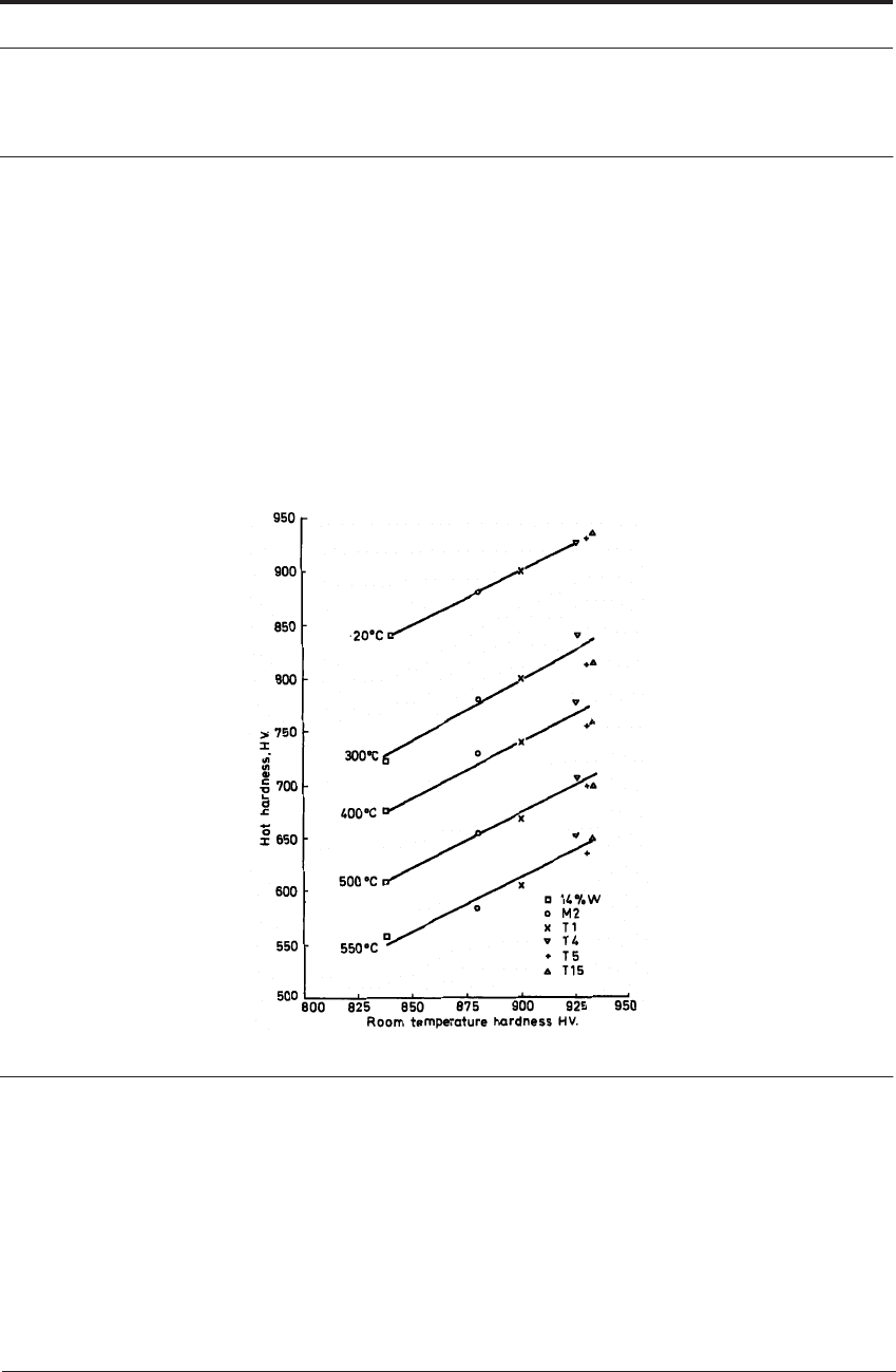
FIGURE 6.6 Hot hardness vs cold hardness for six high speed steels (Kirk et al
7
)
Figure 6.6
7
shows the hot hardness of six high speed steels with different room temperature
hardness, at temperatures up to 550°C. The results show that, for a range of high speed steels,
room temperature hardness provides an indication of hot hardness also. This relationship is true
only for materials within the range of the high speed steels.
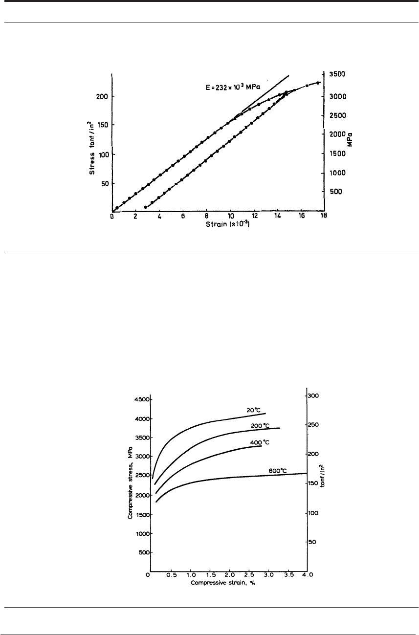
When tested in compression, an elastic limit is observed (Figure 6.7).
8
Young’s modulus is
only slightly higher than that of most engineering steels and varies little with heat treatment.
Plastic deformation is accompanied by strain hardening, as shown in Figure 6.7.
PROPERTIES OF HIGH SPEED STEELS 145
FIGURE 6.7 Compression test on type T1 high speed steel, fully heat treated
8
The compressive strength of fully heat treated high speed steels is of direct relevance to their
performance as cutting tools. Figure 6.8 shows the compressive stress vs plastic strain curves for
fully heat-treated M2 at room temperature and up to 600°C. These curves were obtained by step-
loading cylindrical specimens and can be compared with these for a 1% C steel (Figure 6.3). At
room temperature both the 0.2% yield stress of nearly 3000 MPa (195 tonf/in
2
) and the rate of
strain hardening are greater with high speed steel. At 2% strain the yield stress is over 4000 MPa
(260 tonf/in
2
). It is at elevated temperatures that the advantage of high speed steel over carbon
steel is critical.
FIGURE 6.8 Compressive strain vs plastic stress for fully heat-treated M2 at various temperatures
146 CUTTING TOOL MATERIALS I: HIGH SPEED STEELS
At 400°C the 0.2% yield stress of M2 is over 2000 MPa (130 tonf/in
2
), while with 1% C steel
it was less than 800 MPa (50 tonf/in
2
). Even at 600°C the 0.2% yield stress is 1800 MPa (115
tonf/in
2
) and after 3% strain the yield stress is 2500 MPa (160 tonf/in
2
). Thus, even at 600°C the
strength of M2 high speed steel is high enough to withstand the stress of the order of 1500 MPa
(100 tonf/in
2
) which has been demonstrated at the edge of tools when cutting steel. A tempera-
ture of 600°C at the cutting edge during the machining of steel has been observed at relatively
low cutting speeds (Figure 5.11) and at the tool edge this temperature rises only slowly as the
cutting speed increases (Figure 5.13 and 5.18). The characteristic stress and temperature, and
their distribution in tools used to cut steel is such that cutting speeds on the order of 30-50 m
min
-1
(100 to 150 ft/min) can be employed when machining with high speed steels tools, without
failure through plastic deformation of the cutting edge. In the early days of high speed steels
these were said to possess the quality of “red hardness” by which was meant the ability to cut
steel at speeds where the cutting edge was visibly red hot - i.e. over 600°.
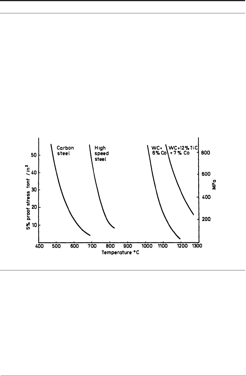
FIGURE 6.9 Hot compression tests: 5% proof stress of tool steels and cemented carbide
9
Since that time the efforts to strengthen further these precipitation-hardened martensitic tool
steels, by modification of the composition and heat treatment, has resulted in some increase in
the yield stress at 600°C. The further increase in hot strength achieved by alloying is real but rel-
atively modest after 85 years of research. It seems unlikely that major improvements in respect
of this property, fundamental to metal cutting, can be accomplished without a basic change in the
structures which control the strength of high speed steels.
Figure 6.9 shows a comparison between the compressive strengths of high speed steel and
other tool materials at a higher temperature range and a lower stress level.
9
The property mea-
sured is the proof stress after 5% reduction. A 5% proof stress of 770 MPa (50 tonf/in
2
) is sup-
ported up to 740°C by high speed steel, compared with 480°C for carbon tool steel and 1000°C
for a cemented carbide.

PROPERTIES OF HIGH SPEED STEELS 147
Other mechanical properties of a number of high speed steels are given in Table 6.2. These are
for steels in the fully heat treated condition as recommended by manufacturers for general use as
cutting tools. The properties are very dependent on heat treatment and Table 6.3 shows how the
properties of M2 high speed steel vary with the hardening temperature and with the tempering
temperature. Tensile tests are not normally carried out on tool steels and the transverse rupture
test is commonly used, the reported value of strength being the maximum tensile stress at the bar
surface before fracture. The strength is high, typical values being 4-5 GPa (260-320 tonf/in
2
).
Another important quality of a tool material for which a measure is being sought is usually
called toughness. In the context of cutting tool materials toughness means the ability of the tool
to continue cutting under difficult conditions for long periods without fracture. When cutting is
interrupted - for example, when turning a slotted bar or an irregular shaped casting or forging, or
when milling - the tool edge is subjected to impact stresses as well as mechanical and thermal
fatigue stresses which may result in local fracture and chipping of the edge. No single test has
been generally accepted as an overall measure of toughness in tool materials. The breaking stress
in the bend test is proposed as one such measure. Impact tests (Charpy or Izod, using test pieces
either unnotched or with a C-notch) place the grades and heat treatments in the same order as
transverse rupture tests. In these tests the tool steel specimens show plastic deformation before
fracture. The amount of plastic deformation is an indication of the ability to absorb energy before
fracture and may, therefore, be related to the probability of tool failure, at least in some condi-
tions of service. In the transverse rupture test the strength value is influenced by the inherent
strength of the alloy and by the presence in the test piece of flaws which may greatly reduce the
measured strength compared with a flaw-free specimen. There is much scatter in individual test
results for this reason. The fracture toughness test is designed to measure the inherent toughness
by determining the energy required to propagate sharp crack. The K
IC
value is given in units of
MPa m
-1/2
Fracture toughness tests carried out by a number of research organizations are in rea-
sonable agreement on the values of the K
IC
parameter for high speed steels. There is some scatter
in test results but, in general, the fracture toughness values place the different grades of steel and
the different heat treatments in the same order as does the bend test.
10,16,18
TABLE 6.2 Typical values of mechanical properties of high speed steels heat-treated for general
use as cutting tool
Grade
Transverse rupture
strength
Fracture
toughness,
K
IC
Izod impact
strength
(un-notched) Hardness
(GPa) (ton f/in
2
) (MPa m
-1/2
) (ft lbs) (HV)
T1 4.6 300 18 15 835
M1 4.8 310 18 24 835
M2 4.8 310 17 25 850
T6 3.0 195 16 9 880
M15 4.0 260 15 13 880
M42 3.4 220 10 13 910

148 CUTTING TOOL MATERIALS I: HIGH SPEED STEELS
TABLE 6.3 Influence of heat treatment on mechanical properties of M2 high speed steel (typical
values)
Apart from chemical composition and heat treatment, a further factor with major influence on
toughness as experienced in the machine shop is the homogeneity and isotropy of the steel. In
high speed steels produced by conventional melting, ingot casting and hot working, the carbide
particles are never uniformly dispersed. After casting they are arranged in clusters, which are
drawn out into lines of closely spaced carbide particles during hot working. In rolled products
the lines are parallel to the rolling direction. The greater the reduction of section in hot working
the more homogeneous is the product. Thus small drills, for example, are reasonably uniform,
but the inhomogeneity is very pronounced in tools of large section. In this respect the quality
varies with the steel making and processing practice of different producers and can be assessed
by comparing the metallographic structures of longitudinal sections with standard micrographs
(e.g. in American National Standard Institute B212.12-91
5
).
In bend tests, the strength in the transverse direction (i.e. when fracture takes place in a direc-
tion normal to the lines of carbide) is higher than in the longitudinal direction and the difference
is greater the more the segregation.
10,11
This is in agreement with practical experience. In mill-
ing cutters, for example, edge fracture is more frequent when the cutting edge is parallel to the
direction of the lines of carbide. The fracture toughness test, however, shows little difference
between the transverse and longitudinal directions, even in severely segregated steel.
10
Fracture
toughness values are a more fundamental quality than strength determined by bend or impact
tests, since they measure a ‘material property’ and are independent of the size and shape of the
test specimen. For measuring the quality of ‘toughness’ in tool materials and predicting tool per-
formance in relation to toughness, however, bend or impact tests seem superior to fracture
toughness tests. For further treatment of this subject see Hoyle.
18
More research is urgently
required to establish a test or tests which can be internationally recognized.
Heat treatment
temperature (
o
C)
Transverse
rupture strength Fracture
toughness K
IC
Izod impact
strength
(un-notched)
Hardness
Hardening Tempering (GPa) (ton f/in
2
) (MPa m
-1/2
) (ft lbs) (HV)
1050 560 4.6 300 19.2 42 660
1150 560 4.7 305 18.6 30 785
1200 560 4.5 290 16.2 27 846
1220 560 4.0 260 16.6 25 850
1250 560 3.8 250 15.1 20 870
1220 450 3.3 210 18.0 28 800
1220 500 3.8 250 18.0 26 820
1220 560 4.6 300 16.6 25 850
1220 600 4.7 305 17.4 30 770
1220 650 3.8 250 18.7 40 600

TOOL LIFE AND PERFORMANCE OF HIGH SPEED STEEL TOOLS 149
One of the main areas in which the experience of the specialist is valuable is in selection of the
optimum grade and heat treatment to secure maximum tool life and metal removal rate for each
particular application. Inadequate toughness will lead to fracture of the tool, giving a short and
erratic tool life. The other factors controlling tool life with high speed steel are now considered.
6.6 TOOL LIFE AND PERFORMANCE OF HIGH SPEED STEEL TOOLS
For satisfactory performance, the shape of the cutting tool edge must be accurately controlled
and is much more critical in some applications than in others. (While the following discussions
seem to be directed at the grinding and honing needed for high speed steels, they are also rele-
vant for the precise sintering operations and edge preparations needed for carbide and ceramic
tools.) Much skill is required to evolve and specify the optimum tool geometry for many opera-
tions, to grind the tools to the necessary accuracy, and to inspect the tools before use. This is not
merely a question of measuring angles and profiles on a macro-scale, but also of inspecting and
controlling the shape of the edge on a very fine scale, within a few tenths of a millimeter of the
edge, involving such features as burrs, chips or rounding of the edge.
In almost all industrial machining operations, the action of cutting gradually changes the shape
of the tool edge so that in time the tool ceases to cut efficiently, or fails completely. The criterion
for the end of tool life is very varied - the tool may be reground or replaced when it fails and
ceases to cut; when the temperature begins to rise and fumes are generated; when the operation
becomes excessively noisy or vibration becomes severe; when dimensions or surface finish of
the workpiece change or when the tool shape has changed by some specified amount. Often the
skill of the operator is required to detect symptoms of the end of tool life, to avoid the damage to
the part being machined, caused by total tool failure (see diagrams at end of Chapter 3).
The change of shape of the tool edge is very small and can rarely be observed adequately with
the naked eye. A binocular microscope with a magnification of at least
× 30 is needed even for
preliminary diagnosis of the character of tool wear in most cases. The worn surfaces of tools are
usually covered by layers of the work material which partially or completely conceal them. To
study the wear of high speed tools it has been necessary to prepare metallographic sections
through the worn surfaces, usually either normal to the cutting edge or parallel with the rake
face. The details which reveal the character of the wear process are at the worn surface or the
interface between tool and adhering work material, and the essential features are obscured by
rounding of the edge of the polished section unless special metallographic methods are adopted.
Sections shown here were mostly prepared by:
(1) Mounting the tool in a cold setting resin in vacuum.
(2) Carefully grinding the tool to the required section, using much coolant.
(3) Lapping on metal plates with diamond dust.
(4) Polishing on a vibratory polishing machine using a nylon cloth with one micron diamond
paste.
Observations have shown that the shape of the tool edge may be changed by plastic deforma-
tion as well as by wear. The distinction is that a wear process always involves some loss of mate-
rial from the tool surface, though it may also include plastic deformation locally, so that there is
no sharp line separating the two. The use of the term wear is, in the minds of many people, syn-

150 CUTTING TOOL MATERIALS I: HIGH SPEED STEELS
onymous with abrasion - the removal of small fragments when a hard body slides over a softer
surface, typified by the action of an abrasive grit in a bearing. There are, however, other pro-
cesses of wear between metallic surfaces, and a mechanism of metal-transfer is frequently
described in the literature. This term is used for an action in which very small amounts of metal,
often only a relatively small number of atoms, are transferred from one surface to the other,
when the surfaces are in sliding contact, the transfer taking place at very small areas of actual
metallic bonding.
Both of these mechanisms may cause wear on cutting tools, but they are essentially processes
taking place at sliding surfaces. There are parts of the tool surface and conditions of cutting
where the work material slides over the tool as in the classical friction model, but, as argued in
Chapter 3, it is characteristic of most industrial metal cutting operations that the two surfaces are
seized together over a large part of the contact area, and under conditions of seizure there is no
sliding at the interface. Wear under conditions of seizure has not been studied extensively, and
investigations of cutting tool wear are in an uncharted area of tribology. The wear and deforma-
tion processes which have been observed to change the shape of high speed steel tools when cut-
ting steel and other high melting point metals are now considered.
12
6.6.1 Superficial plastic deformation by shear at high temperature
When cutting steel and other high melting-point materials at high rates of speed and feed, a
characteristic form of wear is the formation of a crater, a hollow in the rake face some distance
behind the cutting edge, shown diagrammatically in Figure 6.10. The crater is located at the hot-
test part of the rake surface, as demonstrated by the method of temperature estimation described
in Chapter 5 and illustrated in Figure 5.11. In Figure 5.11a the beginnings of the formation of a
crater can be observed. The small ridge just beyond the hottest part on the rake face consists of
tool material sheared from the hottest region and piled up behind. This is shown at higher magni-
fication in Figure 6.11. In this case the work material was a very low carbon steel, the cutting
speed was 183 m min
-1
(600 ft/min), and the cutting time was 30 s. The maximum temperature
at the hottest position was approximately 950°C.
FIGURE 6.10 Cratering wear in relation to temperature contours
Tool
ork
TOOL LIFE AND PERFORMANCE OF HIGH SPEED STEEL TOOLS 151
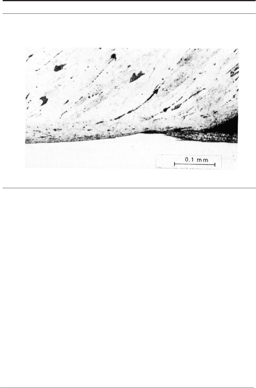
FIGURE 6.11 Section through rake face of tool. As Figure 5.11, back of crater in high speed steel tool
after cutting iron
12
The steel chip was strongly bonded to the rake face, and this metallographic evidence demon-
strates that the stress required to shear the low carbon steel in the flow-zone, at a strain rate of at
least 10
4
s
-1
, was high enough to shear the high speed steel where the temperature was about
950°C. Shear tests on the tool steel used in this investigation gave a shear strength of 100 MPa (9
tonf/in
2
) at 950°C at a strain rate of 0.16 s
-1
. It is unexpected to find that nearly pure iron can
exert a stress high enough to shear high speed steel.
This is possible because:
(1) The yield stress of high speed steel is greatly lowered at high temperature.
(2) The rate of strain of the low carbon steel in the flow-zone is very high, while the rate of
strain in the high speed steel, although it cannot be estimated, can be lower by several orders
of magnitude.
(3) In both materials the yield stress increases with the strain rate.
This wear mechanism has been observed on tools used to cut many steels. Figure 6.12 shows
cratering of high speed steel tools used to cut austenitic stainless steel.The shearing away of suc-
cessive layers of tool steel is particularly well seen in Figure 6.13 at the rear end of the crater. It
occurs also when cutting titanium and its alloys as well as nickel and its alloys. When cutting the
stronger alloys it occurs at much lower cutting speeds than when cutting the commercially pure
metals. This is because the shear stress is higher and the tool is therefore sheared at lower inter-
face temperatures.
However, it always occurs at the regions of highest temperature at the tool work interface, and
when cutting nickel alloys, it has been observed at the cutting edge (Figure 6.14). It also occurs
on a tool flank when the tool is severely worn with accompanying high temperatures.
152 CUTTING TOOL MATERIALS I: HIGH SPEED STEELS
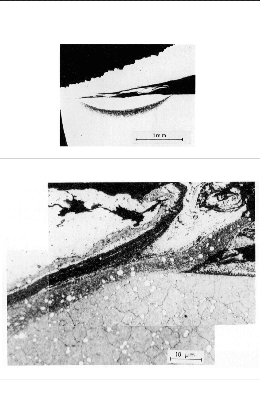
FIGURE 6.12 Crater in high speed steel tool used to cut austenitic stainless steel. Etched to show heat-
affected region below crater filled with work material. (After Wright and Trent
12
)
FIGURE 6.13 End of crater after cutting austenitic stainless steel (After Wright and Trent
12
)