Trent E.M., Wright P.K. Metal Cutting
Подождите немного. Документ загружается.


HEAT IN AREAS OF SLIDING 113
As mentioned in Chapter 3, Wallbank obtained evidence that, even with a sharp tool, when
cutting under conditions where a flow-zone is present, the work material may be in contact with
the clearance face for a distance of the order of 0.2 mm below the cutting edge of a tool with a
conventional clearance angle of about 6°. The workpiece is much more rigid than the chip and
the feed force is too low to deflect it to maintain contact with the clearance face for a length
greater than this. This contact length is too short for the generation of high temperatures in a
flow-zone on the clearance face, as long as the tool remains sharp and the clearance angle is
large.
With certain types of tooling, for example form tools or parting-off tools, a large clearance
angle would seriously weaken the tool or make it too expensive, and clearance angles as low as
1° are employed. With such small clearance angles there is a risk of creating a long contact path
on the clearance face which becomes a third heat source, similar in character to the flow-zone on
the rake face. Even with normal clearance angles, prolonged cutting results in flank wear, in
which a new surface is generated on the tool more or less parallel to the direction of cutting. The
work material is often seized to this ‘wear land’ as to the rake face of the tool, Figure 3.7, and
when the worn surface is long enough, the flow-zone in this region becomes a serious heat
source.
Temperatures generated at the worn surface may be higher than on the rake surface of the
same tool because the work material moves across this surface at the cutting speed of the opera-
tion, while the chip speed over the rake face may be a half or a third of this speed, or lower. Gen-
eration of high temperatures in this region is usually followed immediately by collapse of the
tool. Thus, these preceding discussions have practical importance which should be considered
by tool designers, especially for parting-off and form tools.
5.5 HEAT IN AREAS OF SLIDING
When cutting at very low speeds there may be sliding rather than seizure at the interface. At
higher cutting speeds there may be sliding or intermittent interfacial contact between work and
tool materials at peripheral regions of the contact area (Figure 3.15). Where the conditions at the
tool/work interface are those of sliding contact, the mode of heat generation is very different.
The shearing of very small, isolated metallic junctions provides numerous very short-lived tem-
perature surges at the interface. This is likely to give rise to a very different temperature pattern
at the tool/work interface compared with that of the seized flow-zone.
It seems probable that the mean temperatures will be lower, because a much smaller amount of
work is required to shear the isolated junctions, but localized high temperatures could also occur
at any part of the interface. There is likely to be more even temperature distribution over the con-
tact area than under conditions of seizure. The direct effects of heat generated at sliding contact
surfaces have to be taken into consideration in a complete account of metal cutting. However,
when considering the range of cutting conditions under which problems of industrial machining
arise, the effects of heat from areas of sliding contact can probably be neglected without seri-
ously distorting the understanding of the machining process.

114 HEAT IN METAL CUTTING
5.6 METHODS OF TOOL TEMPERATURE MEASUREMENT
The difficulty of calculating temperatures and temperature gradients near the cutting edge,
even for very simple cutting conditions, gives emphasis to the importance of methods for mea-
suring temperature. This has been an important objective of research and some of the experimen-
tal methods explored are now discussed.
5.6.1 Tool/work thermocouple
The most extensively used method of tool temperature measurement has employed the tool
and the work material as the two elements of a thermocouple.
16
The thermoelectric e.m.f. gener-
ated between the tool and workpiece during cutting is measured using a sensitive millivoltmeter.
The hot junction is the contact area at the cutting edge, while an electrical connection to a cold
part of the tool forms one cold junction. The tool is electrically insulated from the machine tool
(usually a lathe). The electrical connection forming the cold junction with the rotating workpiece
is more difficult to make, and various methods have been adopted, a form of slip-ring often
being used.
Care must be taken to avoid secondary e.m.f. sources such as may arise with tipped tools, or
short circuits which may occur if the chip makes a second contact with the tool, for example on
a chip breaker. The e.m.f. can be measured and recorded during cutting, and, to convert these
readings to temperatures, the tool and work materials, used as a thermocouple, must be cali-
brated against a standard couple such as chromel-alumel. Each different type of tool and work
material used must be calibrated.
There are several sources of error in the use of this method. The tool and work materials are
not ideal elements of a thermocouple: the e.m.f. tends to be low, and the shape of the e.m.f.-tem-
perature curve is far from a straight line. It is doubtful whether the thermo-e.m.f. from a station-
ary couple, used in calibration, corresponds exactly to that of the same couple during cutting
when the work material is being severely strained. The tool/work thermo-couple method has
nevertheless been used successfully by many workers to investigate specific areas of metal cut-
ting - for example, to compare the machinability of different work materials, the effectiveness of
coolants and lubricants or the performance of different tool materials.
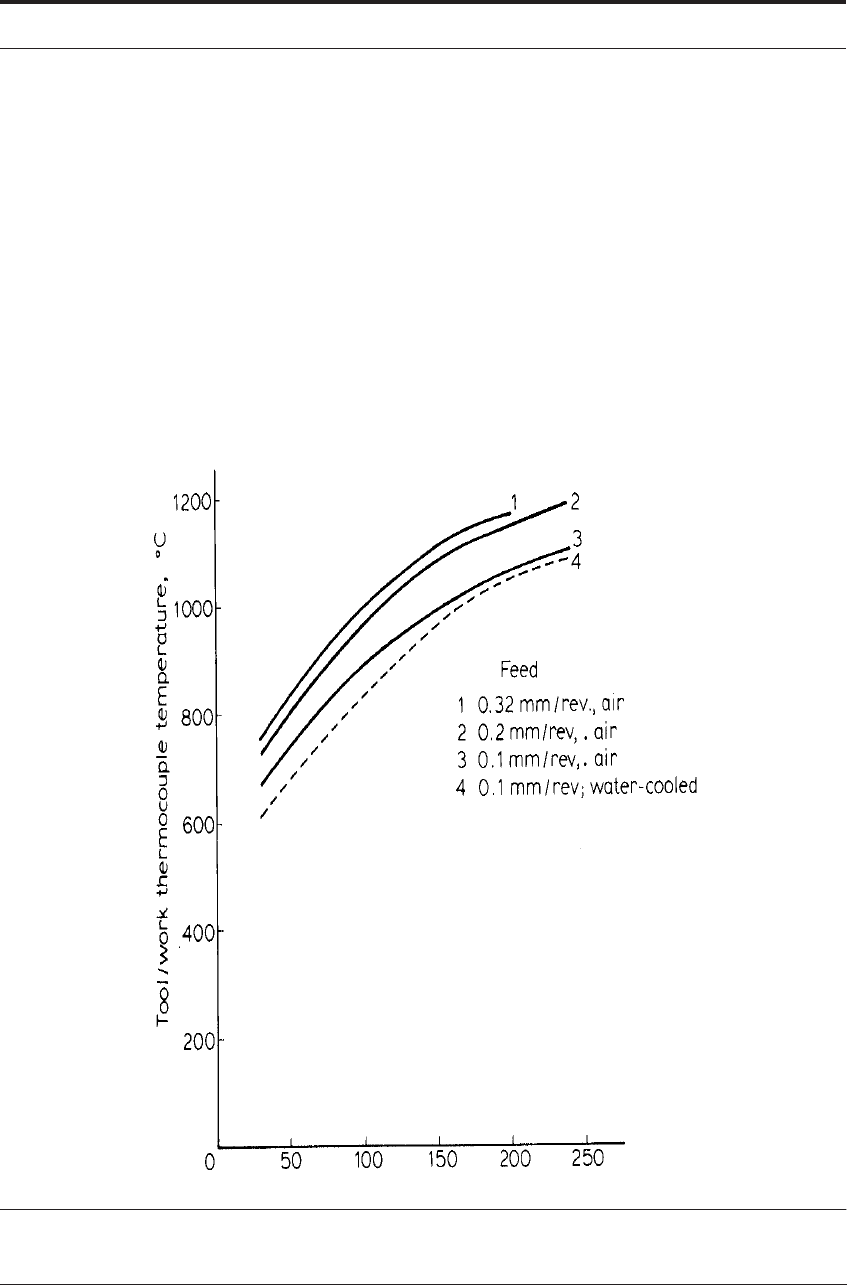
As an example, Kurimoto and Barrow cut a low-alloy engineering steel using a steel cutting
grade of cemented carbide tool over a range of speeds and feeds in air and using different cutting
lubricants.
17
Figure 5.9 shows the temperature determined, plotted against cutting speed for
three different values of feed, and a comparison of cutting in air and with water as a cutting fluid.
The results, the mean of 3 to 12 measurements, are consistent. They indicate an increase in tem-
perature with increments in speed and feed, and a small lowering of temperature when water was
used as a coolant. Temperatures over 1000°C are recorded for speeds of 120 m min
-1
(400ft/min)
and above - conditions commonly used in machine shops. This method is useful in demonstrat-
ing the influence of such variable parameters, but the significance to attach to the numerical val-
ues for temperature which it provides is uncertain.
It is demonstrated later that there are very steep temperature gradients across the contact area
when machining steel at high speed, with temperature differences of 300
°
C or greater at different
positions. It is uncertain whether the tool/work thermo-couple measures the lowest temperature
METHODS OF TOOL TEMPERATURE MEASUREMENT 115
at the interface or a mean value. It is unlikely that it records the highest temperature in the con-
tact area.
While this method has been used effectively to study the influence of parameters in specific
areas of machining, there does not seem to have been any attempt to correlate the results to give
a unified picture of interface temperature in relation to speed, feed, tool design and cutting con-
ditions for a wide range of work materials.
Errors arising from uncertain calibration of the thermocouple can be partially eliminated by
using two different tool materials to cut the same bar of work material, simultaneously, under the
same conditions.
18
The e.m.f. between the two tools is measured. If it can be assumed that the
temperatures at the interfaces of the two tools are the same, then the temperature can be deter-
mined from the measured e.m.f. by calibration of a thermocouple of the two tool materials. Few
results have been reported using this method and, at best, a mean temperature at the contact area
can be determined.
FIGURE 5.9 Tool temperature (tool/work thermocouple); work material is a low alloy engineering steel
and the tool is a cemented carbide (Data from Kurimoto and Barrow
17
)

116 HEAT IN METAL CUTTING
5.6.2 Inserted thermocouples
Measurement of the distribution of temperature in the tool has been the objective of much
experimental work. A simple but very tedious method is to make a hole in the tool and insert a
thermocouple in a precisely determined position close to the cutting edge.
19
This must be
repeated many times with holes in different positions to map the temperature gradients. The
main error in this method arises because the temperature gradients near the edge are very steep,
and holes large enough to take the thermocouple overlap a considerable range of temperature. If
the hole is positioned very precisely, this may be a satisfactory method for comparing the tool
temperature when cutting different alloys, but the method is not likely to be satisfactory for
determining temperature distribution.
5.6.3 Radiation methods
Several methods have been developed for the measurement of radiation from the heated areas
of the tool. In some machining operations, the end clearance face is accessible for observation,
for example in planing a narrow plate. The end clearance face may be photographed, using film
sensitive to infra-red radiation. The heat image of the tool and chip on the film is scanned using
a micro-photometer, and from the intensity of the image the temperature gradient on the end face
of the tool is plotted.
20
The results show that the temperature on this face is at a maximum at the
rake surface at some distance back from the cutting edge, while the temperature is lower near the
cutting edge itself. This method gives information only about the temperature on exposed sur-
faces of the tool.
A more refined but difficult technique using radiant heat measurement involves making holes,
either in the work material or in the tool to act as windows through which a small area (e.g. 0.2
mm dia.) on the rake surface of the tool can be viewed.
4
The image of the hot spot is focussed
onto a PbS photo-resistor which can be calibrated to measure the temperature. By using tools
with holes at different positions, a map can be constructed showing the temperature distribution
on the rake face. A few results using this method have been published showing temperatures
when cutting steel at high speeds using carbide tools. These show very high temperatures (up to
1200°C) and steep gradients with the highest temperature well back from the cutting edge on the
rake face. This method requires very exacting techniques to achieve a single temperature gradi-
ent, and it has been used to estimate the temperature on the flank of carbide tools used to cut
steel.
21
5.6.4 Changes in hardness and microstructure in steel tools
Much more information about temperature distribution near the cutting edge of tools may be
obtained by using the tool itself to monitor the temperature. The room temperature hardness of
hardened steel decreases after re-heating, and the loss in hardness depends on the temperature
and time of heating. The hardness of a hardened carbon tool steel and a fully heat-treated high
speed steel is a function of the re-heat temperature.
Carbon tool steels start to lose hardness when re-heated to 250°C and the hardness is greatly
reduced after heating to 600°C. Fully heat-treated high-speed steel tools are not softened appre-
ciably until 600°C is exceeded. Between 600 and about 850°C the hardness falls rapidly, but it

METHODS OF TOOL TEMPERATURE MEASUREMENT 117
rises again at still higher re-heat temperatures if the steel is rapidly cooled, as it is in the heat
affected zone of the tools. By calibrating the hardness against the temperature and time of heat-
ing, a family of curves can be obtained for any tool steel. Then, if the hardness in any heat-
affected region is measured and the time of heating is known, the temperature to which it was
heated can be determined by comparing the data in the worn tool areas with the standardized cal-
ibration charts.
22-26
This method has been used to estimate the temperature in critical parts of gas turbines, piston
engines and other structures where thermocouples cannot be readily employed. Plugs of a cali-
brated tool steel are inserted and after use are removed for hardness testing.
22
For temperature
measurement in cutting tools, clamped tool tips are used and hardness tests are carried out after
machining for a known time. The heat-affected region occupies a few cubic millimeters near the
cutting-edge.
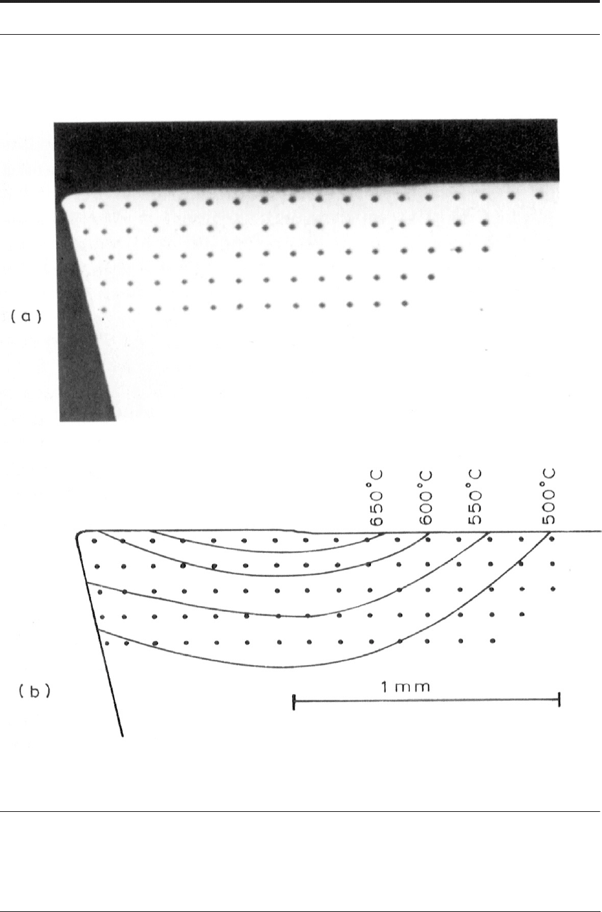
The tool may be sectioned through the cutting edge, polished and a series of hardness tests
made to cover the heat-affected region (Figure 5.10) or the rake surface may be polished and
tested. Since the heated area is small and temperature gradients may be steep, the indentations
must be closely-spaced, e.g. 0.1 mm apart. The indentations must therefore be small and an
accurate micro-hardness machine must be used. The hardness tests in Figure 5.10a were made
using a Vickers pyramidal diamond at 300 gms load. Using this method the temperature at any
position can be estimated within 25
°
C within the temperature range where the tools are softened.
Carbon steel tools are useful for determining tool temperatures when cutting non-ferrous met-
als of low melting point, such as copper and its alloys, but are of little use for temperature esti-
mation when cutting steel. High-speed steel tools have been used for determining temperatures
when cutting steel, nickel alloys, titanium alloys and other high melting point materials.
Temperatures of about 600
°
C occur frequently when cutting steel with high speed steel tools.
Temperatures as low as this cannot be determined using a fully heat-treated high-speed steel tool
but, with tools tempered at a low temperature after hardening (e.g. 400
°
C), the hardness first
increases up to 600
°
C and then decreases at higher temperatures.
Micro-hardness measurements on tools heat treated in this way can be used to estimate tem-
peratures in the tool edge region which are often about 500-650
°
C. Figure 5.10b shows the tem-
perature contours derived from the hardness indentations in Figure 5.10a. In this example, a
medium carbon steel had been cut at 27 m min
-1
(90 ft/min). The maximum temperature on the
rake face was 700°C at a position about 0.75 mm from the cutting edge.
The hardness decrease after heating hardened steel tools is the result of changes in microstruc-
ture. The structural changes can be observed by optical and electron microscopy. With carbon
steels and some high speed steels these changes are usually too gradual to permit positive identi-
fication of a structure characteristic of a narrow temperature range, but Wright demonstrated
that, with certain high speed steels (e.g. cobalt containing steels such as M34 or M42), distinct
modifications to structure occur at approximately 50°C intervals between 600 and 900°C, which
permits measurement of temperature with an accuracy of approximately 25
°
C within the heat
affected region.
24
118 HEAT IN METAL CUTTING
FIGURE 5.10 Section through tool used to cut medium carbon steel at 27 m min
-1
(90 ft/min) and 0.25
mm/rev feed (a) Photomicrograph showing micro-hardness indentations (b) Isotherms determined by
hardness measurements
METHODS OF TOOL TEMPERATURE MEASUREMENT 119
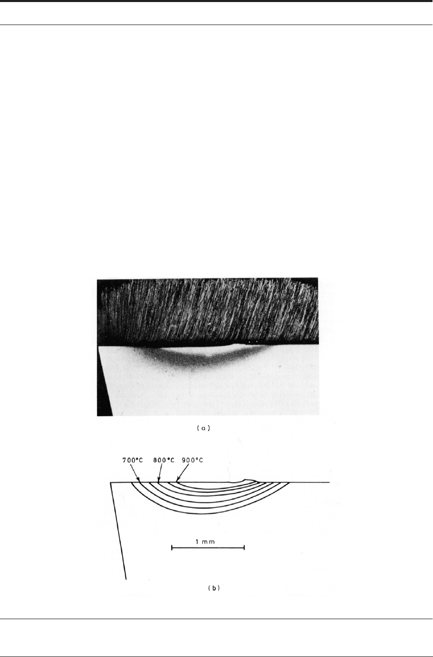
Figure 5.11a is a photomicrograph of an etched section through the cutting edge of a Type
M34 high-speed steel tool used to cut a very low carbon steel at 183 m min
-1
(600 ft/min) at a
feed rate of 0.25 mm/rev for a time of 30 s. The polished section was etched in 2% Nital (a solu-
tion of HNO
3
in alcohol). The darkened area forming a crescent below the rake face defines the
volume of the tool heated above 650
°
C during cutting.
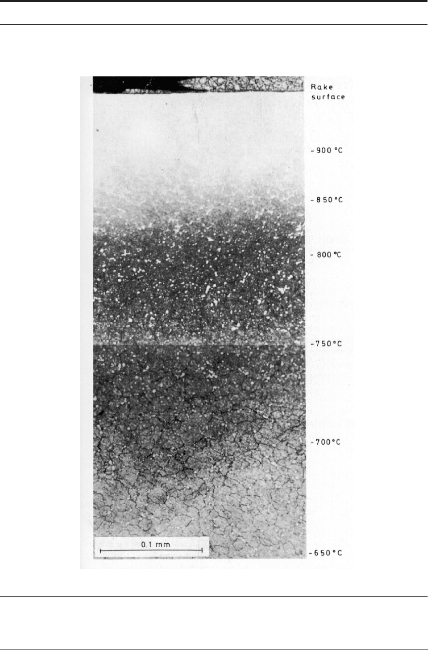
The structures within this region are shown at higher magnification in Figure 5.12 with the
temperature corresponding to each structure. The light area in the center of the heat-affected
region had been above 900°C. The structure became austenitic and this small volume of the tool
was re-hardened when cutting stopped and it cooled very rapidly to room temperature. The tool
rake surface can be re-polished after use and etched to determine temperature distribution in
three dimensions in the tool.
Figure 5.13a shows the structural changes just below the rake face of a tool used under the
same conditions of cutting. Figure 5.11a is thus a section along the line O-B
´ in Figure 3.17 and
5.13a. Figures 5.11b and 5.13b show the temperature contours derived from the structural
changes.
FIGURE 5.11 (a) Section through tool used to cut very low carbon steel at high speed, etched in Nital to
show heat-affected region (b) Temperature contours derived from structural changes in (a)
24
120 HEAT IN METAL CUTTING
FIGURE 5.12 Structural changes and corresponding temperatures in high speed steel tool
24

MEASURED TEMPERATURE DISTRIBUTION IN TOOLS 121
FIGURE 5.13 (a) Rake face of tool used to cut very low carbon steel at high speed, etched to show heat-
affected region; (b) temperature contours derived from structural changes in (a)
26
The micro-hardness method is time consuming and requires very accurate hardness measure-
ment. The structural change method requires experience in interpretation of structures but,
where it can be used, it is as accurate and much more rapid. In conjunction with metallographic
studies of the interface, important information can be gained which is lost using micro-hardness
alone.
The main limitations of both methods are that they can be used only within the cutting speed
limitations of steel tools and where relatively high temperatures are generated. Commercial
cemented carbide tools can be used at much higher cutting speeds. When heated at temperatures
up to their melting point (about 1300°C) and cooled, normal cobalt-bonded carbides do not
undergo observable changes in hardness or structure. Certain iron-bonded cemented carbides,
however, do undergo structural change at about 800°C.
Dearnley has given metallographic evidence of a sharp structural change in the heat-affected
regions of iron-bonded carbide tools, which can be used as a temperature contour.
25
This opens
the possibility of temperature measurements in tools used to cut high melting-point materials at
much higher speeds. Knowing the character of the heat source, it should be possible, starting
from the estimated temperature distribution at the tool rake face, to treat the subject as a heat-
flow problem and greatly extend the existing knowledge of temperature distribution near the
edge of cutting tools.
5.7 MEASURED TEMPERATURE DISTRIBUTION IN TOOLS
Using the micro-hardness and metallographic methods, a number of investigations of tempera-
ture distribution in cutting tools have been made.
23-26
Results of both theoretical importance and
practical interest have been demonstrated. Temperature distribution in tools used to cut different
work materials is dealt with in relation to machinability in Chapter 9. Here, the influence of cut-
ting speed and feed is discussed on the basis of tests using one work material - a very low carbon
steel (0.04% C). Figure 5.14 shows sections through tools used to cut steel at a feed of 0.25 mm
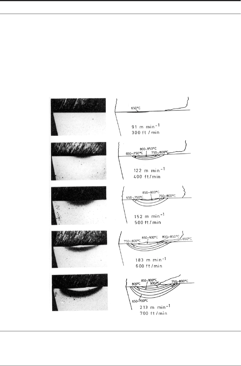
122 HEAT IN METAL CUTTING
(0.010 in) per rev, at cutting speeds from 91 to 213 m min
-1
(300 to 700 ft/min) for a cutting time
of 30 s. The maximum temperature on the rake face of the tool rose as the cutting speed
increased, while the hot spot stayed in the same position. Even at the maximum speed a cool
zone (below 650
°
C) extended for 0.2 mm from the edge, while the maximum temperature,
approximately 1000
°
C, is at a position just over 1 mm from the edge. This demonstrates the
presence of very high temperatures and very steep temperature gradients which can be present in
the tool at the rake face when machining high melting-point metals and alloys under conditions
where the heat source is a thin flow-zone on the chip’s underside.
FIGURE 5.14 Temperature contours in tools used to cut very low carbon steel at a feed of 0.25 mm
(0.010 in) per rev, and at speeds shown for a cutting time of 30 s
26