Jackson M.J. Micro and Nanomanufacturing
Подождите немного. Документ загружается.

Mechanical Micromachining 241
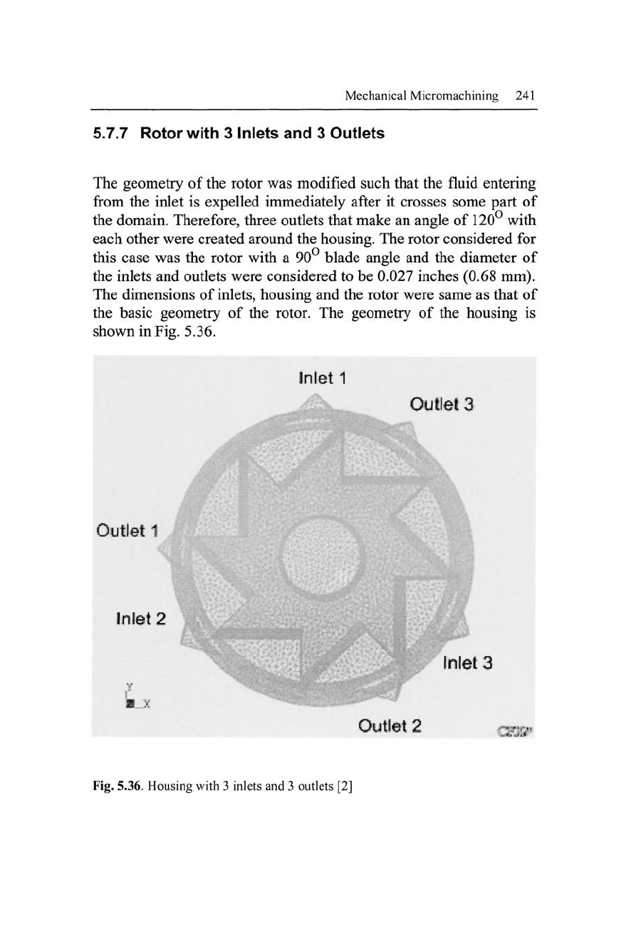
5.7.7 Rotor with 3 Inlets and 3 Outlets
The geometry of the rotor was modified such that the fluid entering
from the inlet is expelled immediately after it crosses some part of
the domain. Therefore, three outlets that make an angle of 120° with
each other were created around the housing. The rotor considered for
this case was the rotor with a 90° blade angle and the diameter of
the inlets and outlets were considered to be 0.027 inches (0.68 mm).
The dimensions of
inlets,
housing and the rotor were same as that of
the basic geometry of the rotor. The geometry of the housing is
shown in Fig. 5.36.
Fig. 5.36. Housing with 3 inlets and 3 outlets [2]
242 Micro- and Nanomanufacturing
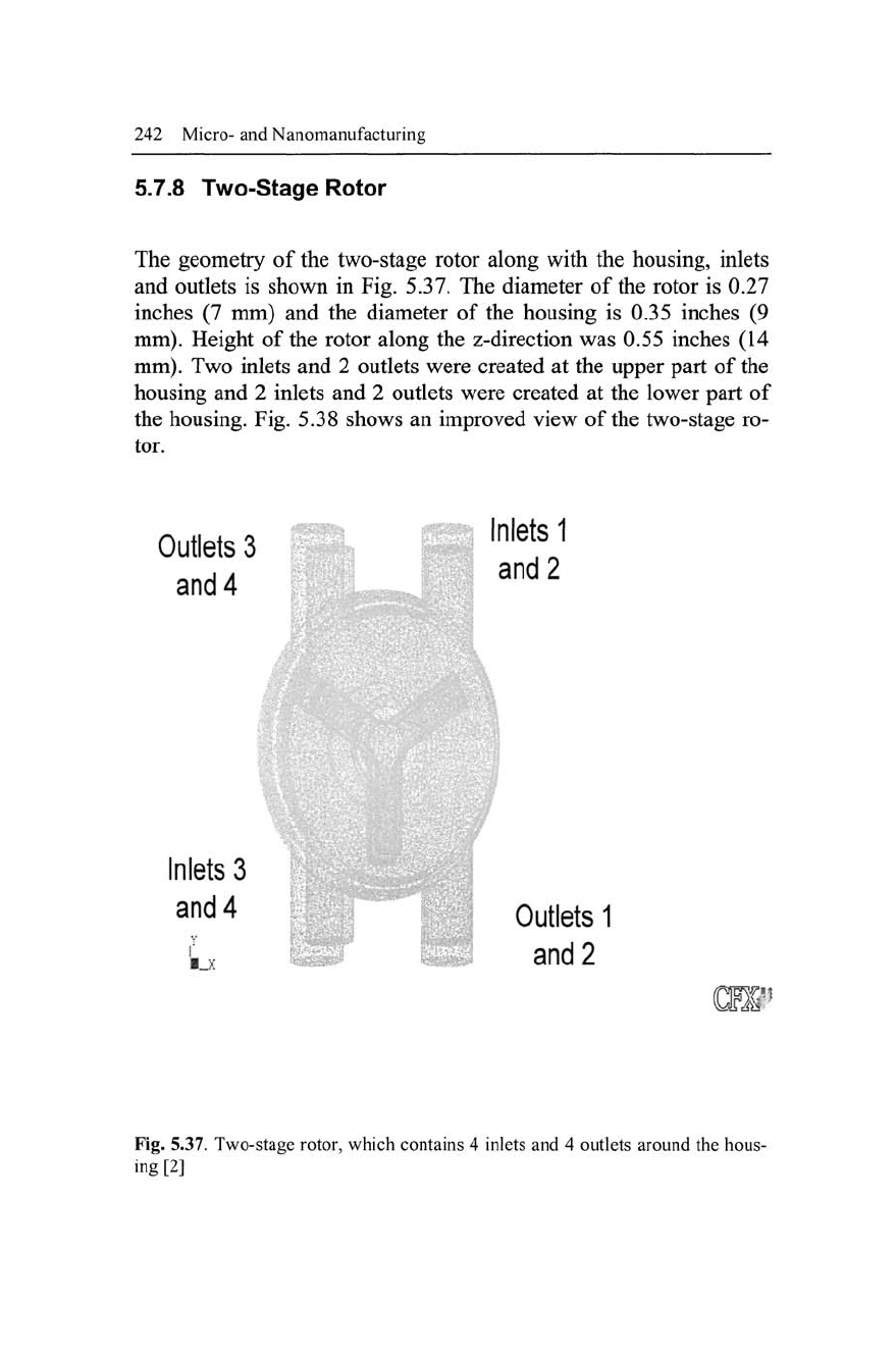
5.7.8 Two-Stage Rotor
The geometry of the two-stage rotor along with the housing, inlets
and outlets is shown in Fig. 5.37. The diameter of the rotor is 0.27
inches (7 mm) and the diameter of the housing is 0.35 inches (9
mm).
Height of the rotor along the z-direction was 0.55 inches (14
mm).
Two inlets and 2 outlets were created at the upper part of the
housing and 2 inlets and 2 outlets were created at the lower part of
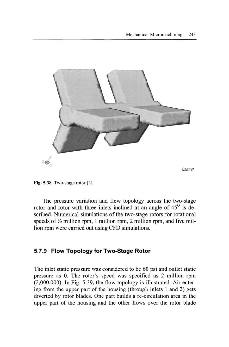
the housing. Fig. 5.38 shows an improved view of the two-stage ro-
tor.
Outlets 3
and 4
Inlets 1
and 2
Inlets 3
and 4
L
Outlets 1
and 2
Fig. 5.37. Two-stage rotor, which contains 4 inlets and 4 outlets around the hous-
ing[2]
Mechanical Micromachining 243
\ w v
*
Fig. 5.38. Two-stage rotor [2]
The pressure variation and flow topology across the two-stage
rotor and rotor with three inlets inclined at an angle of 45° is de-
scribed. Numerical simulations of the two-stage rotors for rotational
speeds of
Vi
million rpm, 1 million rpm, 2 million rpm, and five mil-
lion rpm were carried out using CFD simulations.
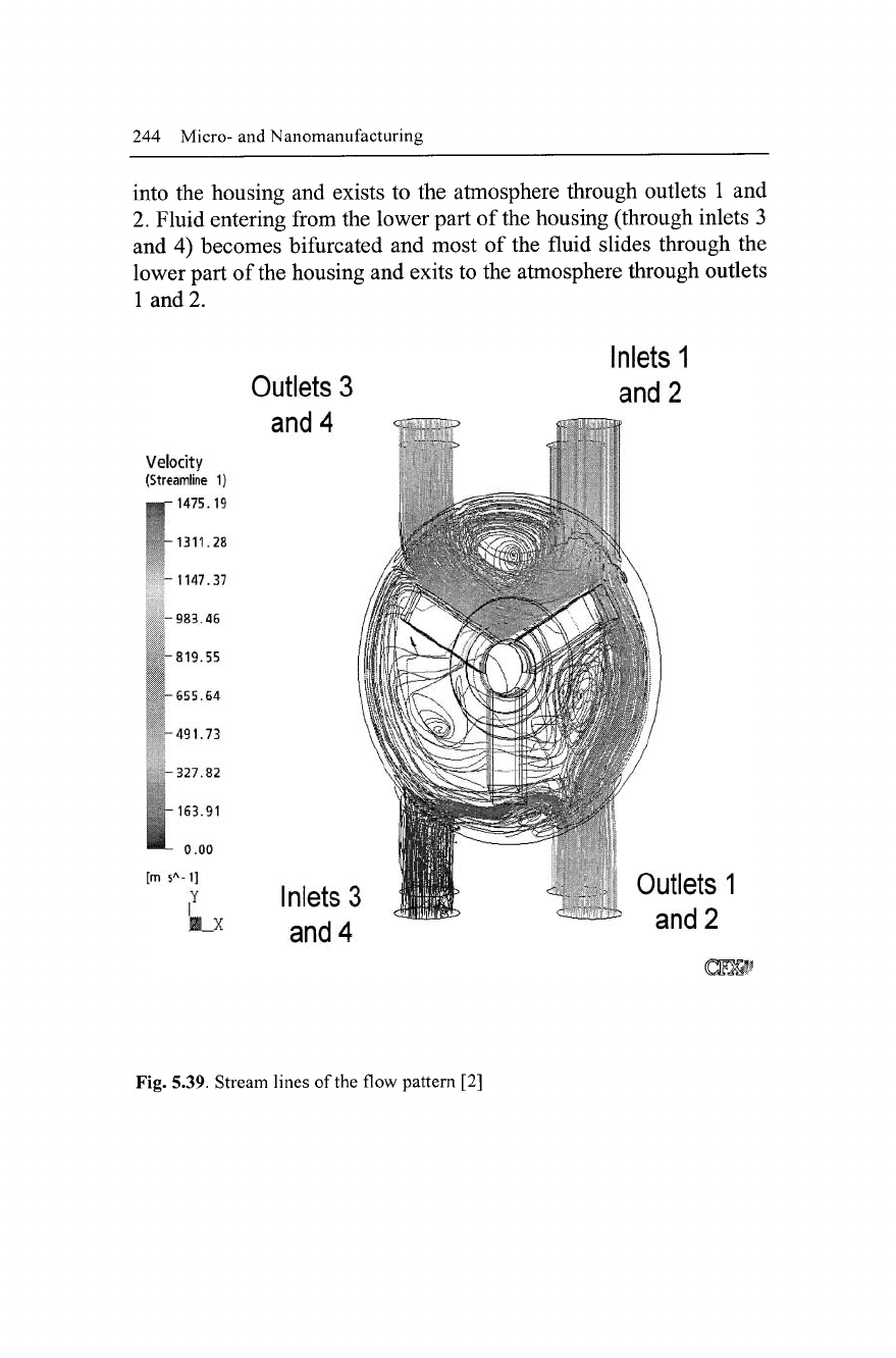
5.7.9 Flow Topology for Two-Stage Rotor
The inlet static pressure was considered to be 60 psi and outlet static
pressure as 0. The rotor's speed was specified as 2 million rpm
(2,000,000). In Fig. 5.39, the flow topology is illustrated. Air enter-
ing from the upper part of the housing (through inlets 1 and 2) gets
diverted by rotor blades. One part builds a re-circulation area in the
upper part of the housing and the other flows over the rotor blade
244 Micro- and Nanomanufacturing
into the housing and exists to the atmosphere through outlets 1 and
2.
Fluid entering from the lower part of the housing (through inlets 3
and 4) becomes bifurcated and most of the fluid slides through the
lower part of
the
housing and exits to the atmosphere through outlets
1 and 2.
Velocity
(Streamline 1)
•p 1475.19
-1311.28
-1147.37
-983.46
-819.55
-655.64
-491.73
-327.82
ill
[m s
A
-1]
i
Y
Outlets
3
and
4
Inlets
1
and
2
.B_X
Inlets
3
and
4
Outlets
1
and
2
Fig. 5.39. Stream lines of the flow pattern [2]
Mechanical Micromachining
245
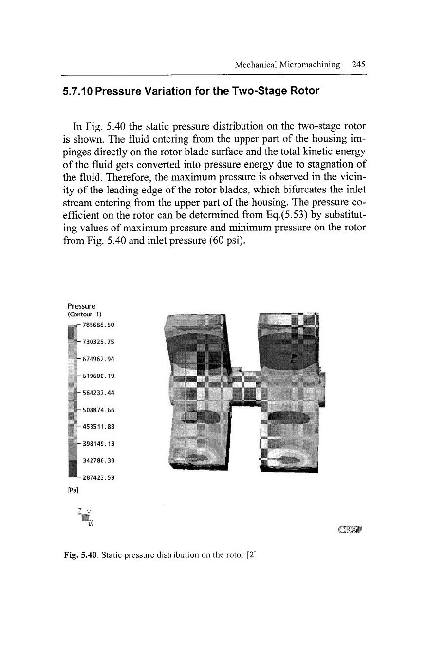
5.7.10 Pressure Variation for the Two-Stage Rotor
In Fig. 5.40 the static pressure distribution
on
the two-stage rotor
is shown. The fluid entering from the upper part
of
the housing im-
pinges directly on the rotor blade surface and the total kinetic energy
of the fluid gets converted into pressure energy due
to
stagnation
of
the fluid. Therefore, the maximum pressure
is
observed
in
the vicin-
ity of the leading edge
of
the rotor blades, which bifurcates the inlet
stream entering from the upper part of the housing. The pressure co-
efficient on the rotor can be determined from Eq.(5.53)
by
substitut-
ing values of maximum pressure and minimum pressure on the rotor
from Fig. 5.40 and inlet pressure (60 psi).
Pressure
(Contour
1)
785688.50
^-730325.75
-674962.94
-619600.19
-564237.44
-508874.66
-453511.88
, -398149.13
1^-342786.38
™-
287423.59
[Pa]
Fig. 5.40. Static pressure distribution on the rotor
[2]
246 Micro- and Nanomanufacturing
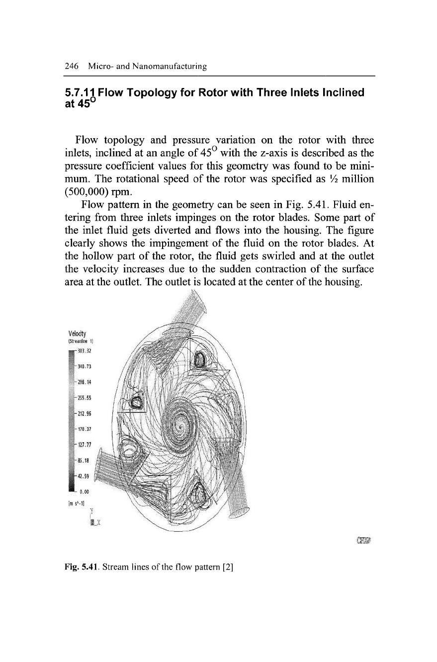
5.7.11 Flow Topology for Rotor with Three Inlets Inclined
at 45°
Flow topology and pressure variation on the rotor with three
inlets,
inclined at an angle of 45° with the z-axis is described as the
pressure coefficient values for this geometry was found to be mini-
mum. The rotational speed of the rotor was specified as Vi million
(500,000) rpm.
Flow pattern in the geometry can be seen in Fig. 5.41. Fluid en-
tering from three inlets impinges on the rotor blades. Some part of
the inlet fluid gets diverted and flows into the housing. The figure
clearly shows the impingement of the fluid on the rotor blades. At
the hollow part of the rotor, the fluid gets swirled and at the outlet
the velocity increases due to the sudden contraction of the surface
area at the outlet. The outlet is located at the center of
the
housing.
Velocity
(Streamline
1)
Fig. 5.41. Stream lines of the flow pattern [2]
Mechanical Micromachining 247
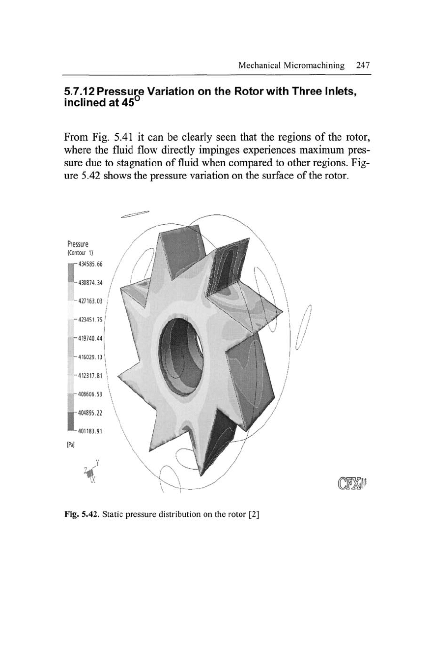
5.7.12 Pressure Variation on the Rotor with Three Inlets,
inclined at 45°
From Fig. 5.41 it can be clearly seen that the regions of the rotor,
where the fluid flow directly impinges experiences maximum pres-
sure due to stagnation of fluid when compared to other
regions.
Fig-
ure 5.42 shows the pressure variation on the surface of the rotor.
Pressure
(Contour
1)
Fig. 5.42. Static pressure distribution on the rotor [2]
248 Micro-
and
Nanomanufacturing
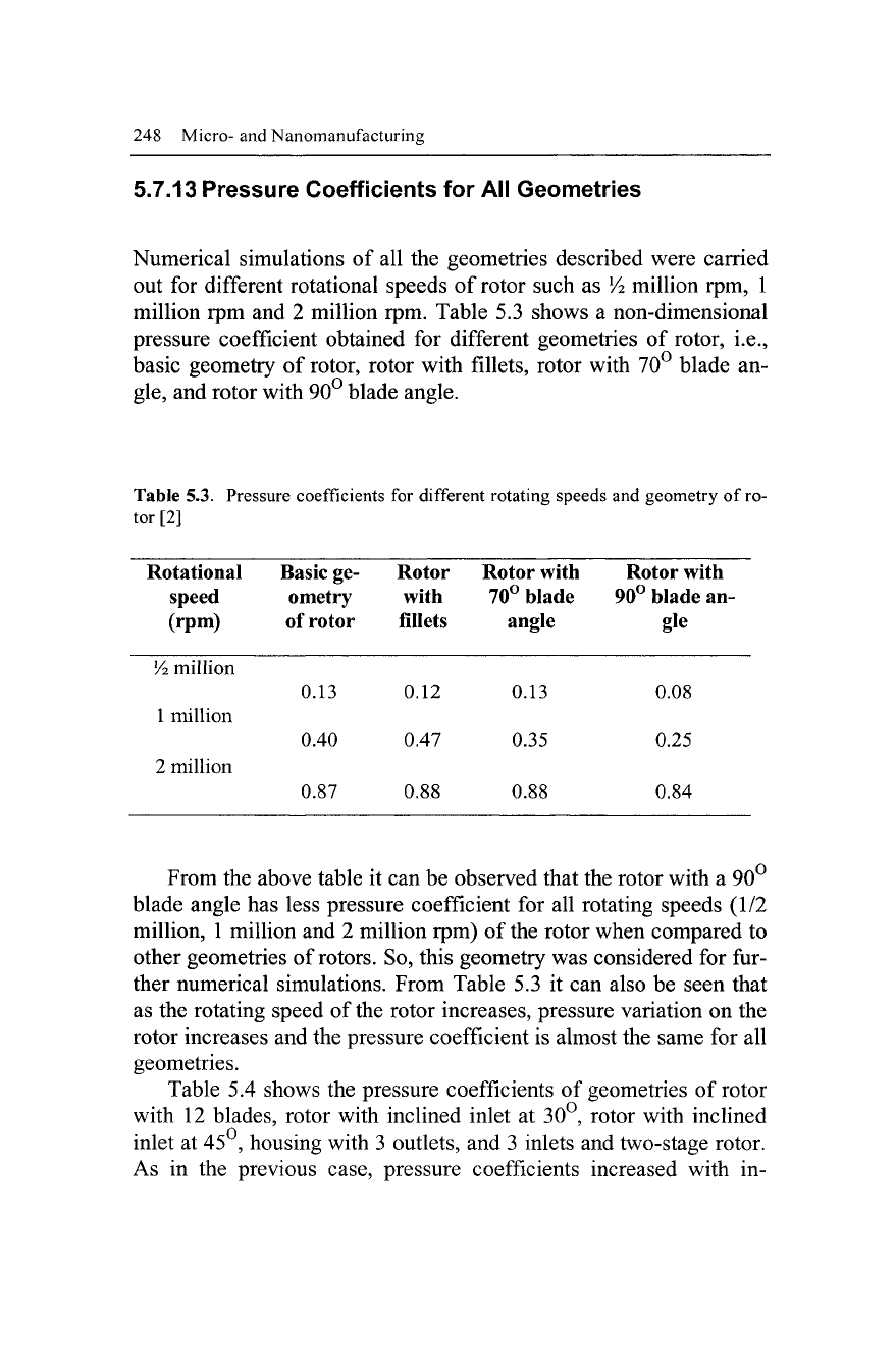
5.7.13 Pressure Coefficients for All Geometries
Numerical simulations of all the geometries described were carried
out for different rotational speeds of rotor such as
Vi
million rpm, 1
million rpm and 2 million rpm. Table 5.3 shows a non-dimensional
pressure coefficient obtained for different geometries of rotor, i.e.,
basic geometry of rotor, rotor with fillets, rotor with 70° blade an-
gle,
and rotor with 90° blade angle.
Table 5.3. Pressure coefficients for different rotating speeds and geometry of
ro-
tor [2]
Rotational Basic ge- Rotor Rotor with Rotor with
speed ometry with 70° blade 90° blade an-
(rpm) of rotor fillets angle gle
Vi
million
0.13 0.12 0.13 0.08
1 million
0.40 0.47 0.35 0.25
2 million
0.87 0.88 0.88 0.84
From the above table it can be observed that the rotor with a 90
blade angle has less pressure coefficient for all rotating speeds (1/2
million, 1 million and 2 million rpm) of the rotor when compared to
other geometries of
rotors.
So, this geometry was considered for fur-
ther numerical simulations. From Table 5.3 it can also be seen that
as the rotating speed of the rotor increases, pressure variation on the
rotor increases and the pressure coefficient is almost the same for all
geometries.
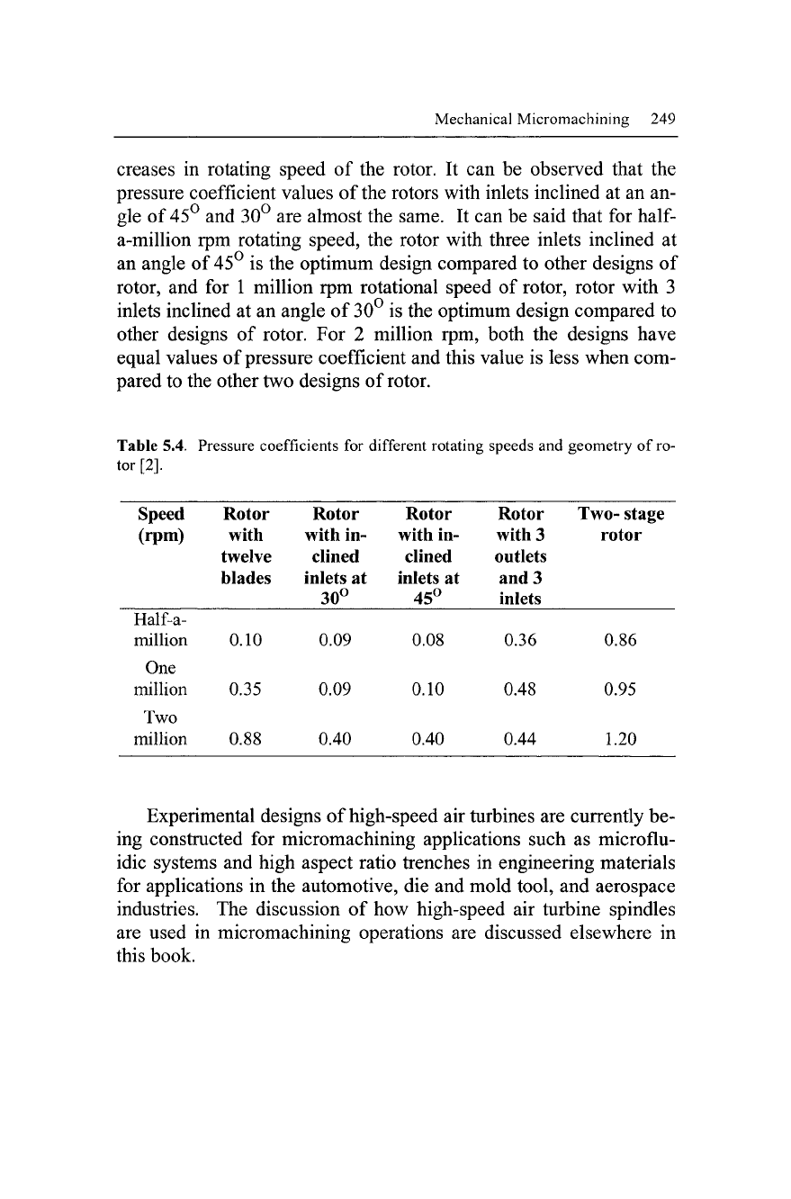
Table 5.4 shows the pressure coefficients of geometries of rotor
with 12 blades, rotor with inclined inlet at 30°, rotor with inclined
inlet at 45°, housing with 3 outlets, and 3 inlets and two-stage rotor.
As in the previous case, pressure coefficients increased with in-
Mechanical Micromachining 249
creases in rotating speed of the rotor. It can be observed that the
pressure coefficient values of the rotors with inlets inclined at an an-
gle of 45° and 30° are almost the same. It can be said that for
half-
a-million rpm rotating speed, the rotor with three inlets inclined at
an angle of 45° is the optimum design compared to other designs of
rotor, and for 1 million rpm rotational speed of rotor, rotor with 3
inlets inclined at an angle of 30° is the optimum design compared to
other designs of rotor. For 2 million rpm, both the designs have
equal values of pressure coefficient and this value is less when com-
pared to the other two designs of rotor.
Table 5.4. Pressure coefficients for different rotating speeds and geometry of ro-
tor [2].
Speed
(rpm)
Half-a-
million
One
million
Two
million
Rotor
with
twelve
blades
0.10
0.35
0.88
Rotor
with in-
clined
inlets at
30°
0.09
0.09
0.40
Rotor
with in-
clined
inlets at
45°
0.08
0.10
0.40
Rotor
with 3
outlets
and 3
inlets
0.36
0.48
0.44
Two-
stage
rotor
0.86
0.95
1.20
Experimental designs of high-speed air turbines are currently be-
ing constructed for micromachining applications such as microflu-
idic systems and high aspect ratio trenches in engineering materials
for applications in the automotive, die and mold tool, and aerospace
industries. The discussion of how high-speed air turbine spindles
are used in micromachining operations are discussed elsewhere in
this book.
250 Micro- and Nanomanufacturing
5.8 Discussion
It can be seen from micromachining analysis that despite the ex-
tremely high strain rates imposed due to high speed cutting, macro-
scale equations can be applied accurately and produce impressive re-
sults.
The most significant differences, however, appear in the
following categories: strain rate, scallop height, and chip type.
Many of the forces are of a similar order of magnitude offering no
significant difference between macro low-speed and micro-high
speed machining. This is important during tool design as small tools
must absorb the same impact forces as larger tools do during impact.
However, when considering the strain rate it can be seen during mi-
cro-high-speed machining the strain rate is 8333 x 10
6
s"
1
compared
to the macro low-speed case of 667 x 10
6
s"
1
, a 12.5 times increase
which relates directly to a 12.5 increase in speed from 20,000 rpm to
250,000 rpm. The increase in strain rate is directly related to the in-
crease in cutting speed, this is expected as the cutter is imparting the
strain and therefore a rate of strain to the material. The lamellae
spacing Ay in Eq. 5.20 has a significant effect on the strain rate,
comparing macro- and micro-scale chips it is found that lamellae are
10 times more closely packed in the high-speed chips than the low
speed chips.
The purpose of milling is to create surfaces that are useful, hence
surface quality should be an important consideration of milling, a
measure of this is scallop height. An improvement is seen in the mi-
cro-high-speed case with a scallop height of 1.58 x
10"
11
m compared
to 8.9 x 10'
9
m for macro slow speeds. Although both values seem
insignificant it must be remembered at the micro-and nanoscale post
process finishing is inappropriate, therefore created structures must
be produced to specification without further processing. In addition,
owing to the aspect ratio small imperfections become serious defects
at small scales. From the calculations it can be seen that there is an
improvement in the scallop height, which is not the improvement re-
quired when considering the scale order of magnitude has changed
by a factor of four. This is because the current spindle speeds
reached are not high enough for effective machining. If this speed is