Jackson M.J. Micro and Nanomanufacturing
Подождите немного. Документ загружается.

Mechanical Micromachining 211
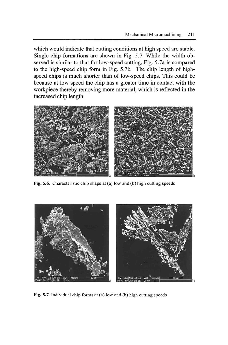
which would indicate that cutting conditions at high speed are stable.
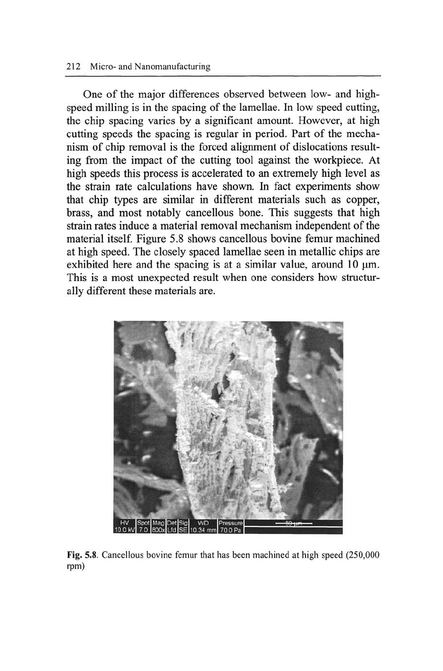
Single chip formations are shown in Fig. 5.7. While the width ob-
served is similar to that for low-speed cutting, Fig. 5.7a is compared
to the high-speed chip form in Fig. 5.7b. The chip length of high-
speed chips is much shorter than of low-speed chips. This could be
because at low speed the chip has a greater time in contact with the
workpiece thereby removing more material, which is reflected in the
increased chip length.
Fig. 5.6. Characteristic chip shape at (a) low and (b) high cutting speeds
Fig. 5.7. Individual chip forms at (a) low and (b) high cutting speeds
212 Micro-and Nanomanufacturing
One of the major differences observed between low- and high-
speed milling is in the spacing of the lamellae. In low speed cutting,
the chip spacing varies by a significant amount. However, at high
cutting speeds the spacing is regular in period. Part of the mecha-
nism of chip removal is the forced alignment of dislocations result-
ing from the impact of the cutting tool against the workpiece. At
high speeds this process is accelerated to an extremely high level as
the strain rate calculations have shown. In fact experiments show
that chip types are similar in different materials such as copper,
brass,
and most notably cancellous bone. This suggests that high
strain rates induce a material removal mechanism independent of the
material
itself.
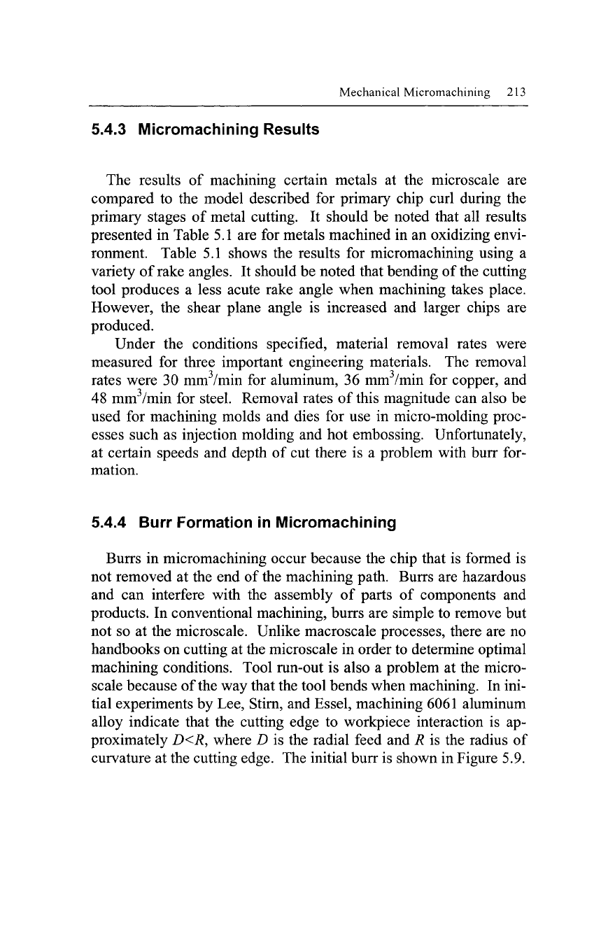
Figure 5.8 shows cancellous bovine femur machined
at high speed. The closely spaced lamellae seen in metallic chips are
exhibited here and the spacing is at a similar value, around 10 |nm.
This is a most unexpected result when one considers how structur-
ally different these materials are.
Fig. 5.8. Cancellous bovine femur that has been machined at high speed (250,000
rpm)
Mechanical Micromachining 213
5.4.3 Micromachining Results
The results of machining certain metals at the microscale are
compared to the model described for primary chip curl during the
primary stages of metal cutting. It should be noted that all results
presented in Table 5.1 are for metals machined in an oxidizing envi-
ronment. Table 5.1 shows the results for micromachining using a
variety of rake angles. It should be noted that bending of the cutting
tool produces a less acute rake angle when machining takes place.
However, the shear plane angle is increased and larger chips are
produced.
Under the conditions specified, material removal rates were
measured for three important engineering materials. The removal
rates were 30 mm
3
/min for aluminum, 36 mm
3
/min for copper, and
48 mmVmin for steel. Removal rates of this magnitude can also be
used for machining molds and dies for use in micro-molding proc-
esses such as injection molding and hot embossing. Unfortunately,
at certain speeds and depth of cut there is a problem with burr for-
mation.
5.4.4 Burr Formation in Micromachining
Burrs in micromachining occur because the chip that is formed is
not removed at the end of the machining path. Burrs are hazardous
and can interfere with the assembly of parts of components and
products. In conventional machining, burrs are simple to remove but
not so at the microscale. Unlike macroscale processes, there are no
handbooks on cutting at the microscale in order to determine optimal
machining conditions. Tool run-out is also a problem at the micro-
scale because of the way that the tool bends when machining. In ini-
tial experiments by Lee, Stirn, and Essel, machining 6061 aluminum
alloy indicate that the cutting edge to workpiece interaction is ap-
proximately D<R, where D is the radial feed and R is the radius of
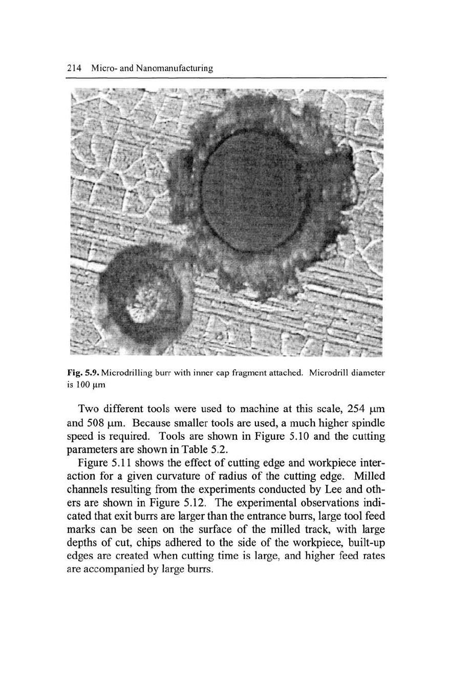
curvature at the cutting edge. The initial burr is shown in Figure 5.9.
214 Micro-and Nanomanufacturing
Fig. 5.9. Microdrilling burr with inner cap fragment attached. Microdrill diameter
is 100 |iim
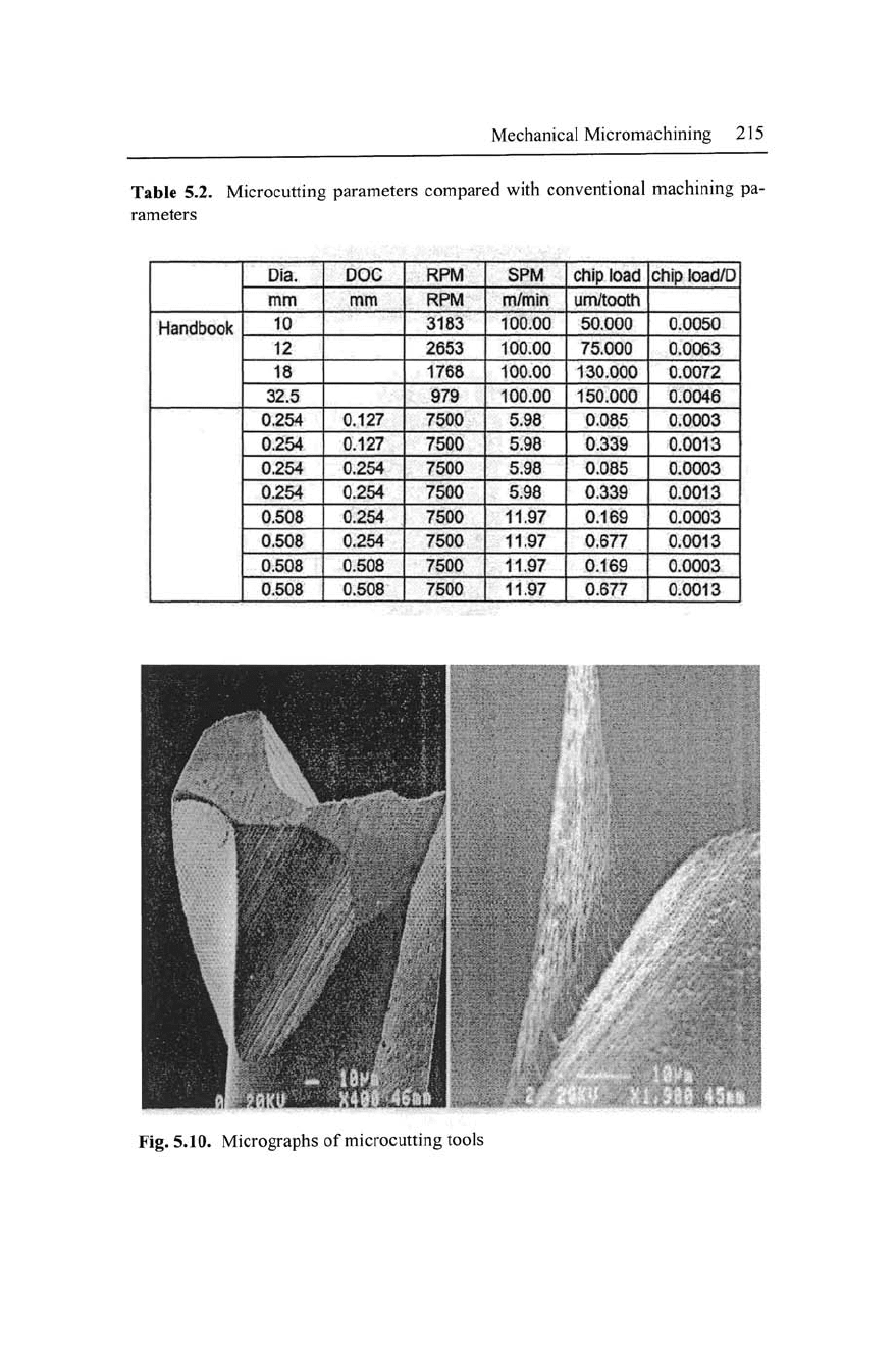
Two different tools were used to machine at this scale, 254 |um
and 508 |um. Because smaller tools are used, a much higher spindle
speed is required. Tools are shown in Figure 5.10 and the cutting
parameters are shown in Table 5.2.
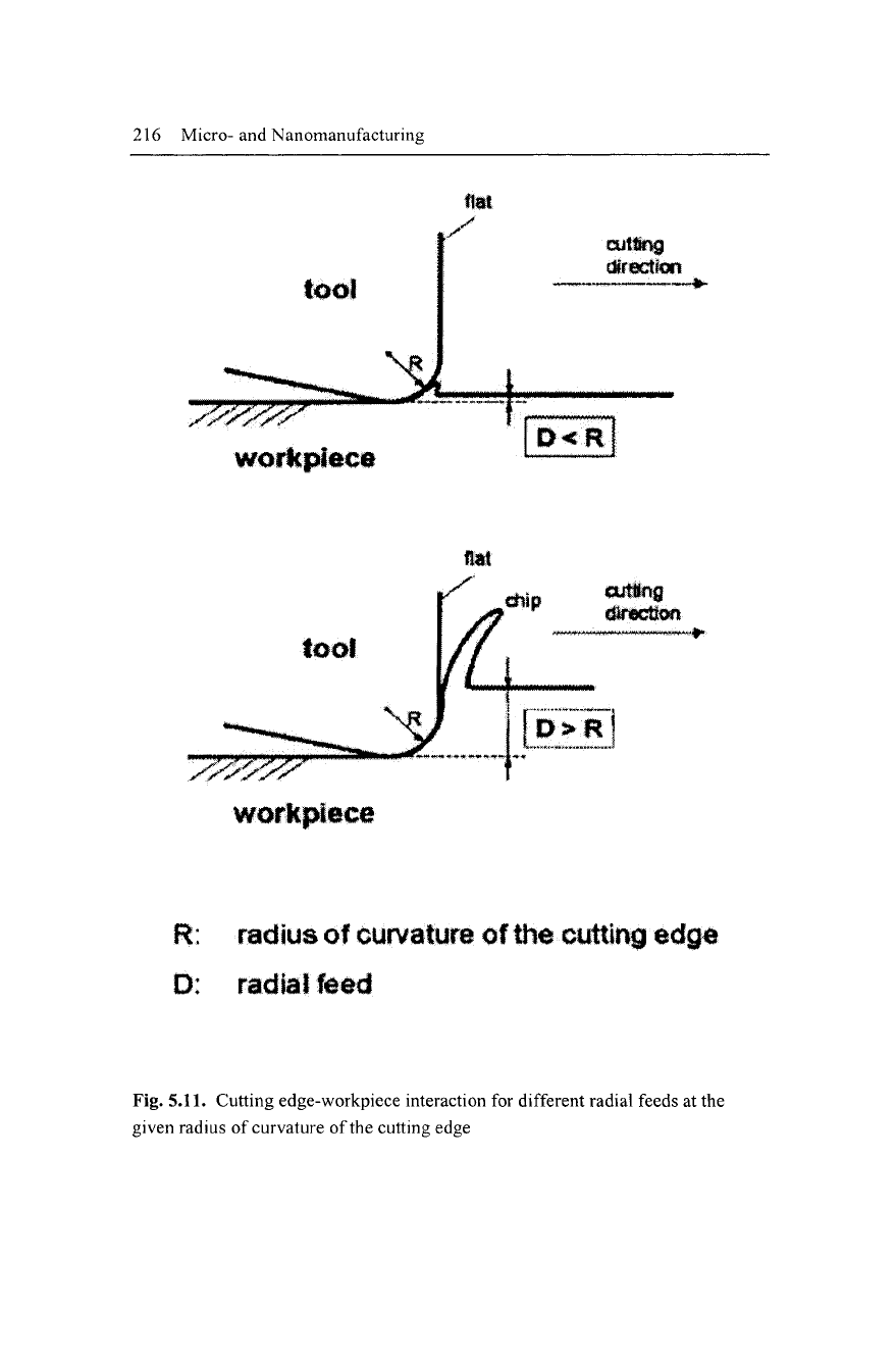
Figure 5.11 shows the effect of cutting edge and workpiece inter-
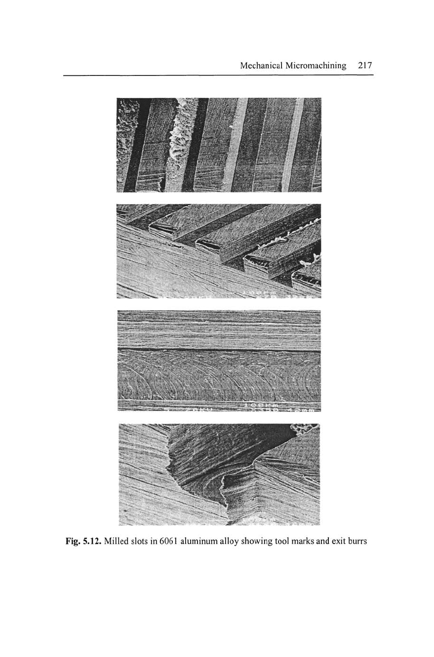
action for a given curvature of radius of the cutting edge. Milled
channels resulting from the experiments conducted by Lee and oth-
ers are shown in Figure 5.12. The experimental observations indi-
cated that exit burrs are larger than the entrance burrs, large tool feed
marks can be seen on the surface of the milled track, with large
depths of cut, chips adhered to the side of the workpiece, built-up
edges are created when cutting time is large, and higher feed rates
are accompanied by large burrs.
Mechanical Micromachining 215
Table 5.2. Microcutting parameters compared with conventional machining pa-
rameters
Handbook
Dia.
mm
10
12
18
32.5
0.254
0.254
0.254
0.254
0.508
0.508
0.508
0.508
DOC
mm
0.127
0.127
0.254
0.254
0.254
0.254
0.508
0.508
RPM
RPM
3183
2653
1768
979
7500
7500
7500
7500
7500
7500
7500
7500
SPM
m/min
100.00
100.00
100.00
100.00
5.98
5.98
5.98
5.98
11.97
11.97
11.97
11.97
chip load
um/tooth
50.000
75.000
130.000
150.000
0.085
0.339
0.085
0.339
0.169
0.677
0.169
0.677
chip load/D|
0.0050
0.0063
|
0.0072
;
0.0046
0,0003
0.0013
0.0003
0.0013
0.0003
0.0013
|
0.0003
I
0.0013
!
Fig. 5.10. Micrographs of microcutting tools
216 Micro-and Nanomanufacturing
tool
workpiece
%/
flat
cutting
direction
W:*M
cutiJng
direcHwi
workpiece
R:
radius
of
curvature
of the cutting
edg*
D: radial feed
Fig.
5.11.
Cutting edge-workpiece interaction for different radial feeds at the
given radius of curvature of the cutting edge
Mechanical Micromachining 217
?ff^
Fig. 5.12. Milled slots in 6061 aluminum alloy showing tool marks and exit burrs
218 Micro- and Nanomanufacturing
Gillespie postulated that burrs are classified in the following terms:
Tear burrs; rollover burrs, Poisson burrs, and cut-off burrs. A tear
bear is the result of material tearing loose from the workpiece rather
than shearing. The rollover burr is essentially a chip that is bent
rather than sheared, resulting in a comparatively large burr. This
type of burr is also known as an exit burr. The Poisson burr is one
that results from the material's tendency to bulge at the sides of the
machined cut when it is compressed until permanent plastic defor-
mation takes place. Figure 5.13 shows the tear and rollover burr
formations.
Fig. 5.13. Tear burr and rollover burr formation
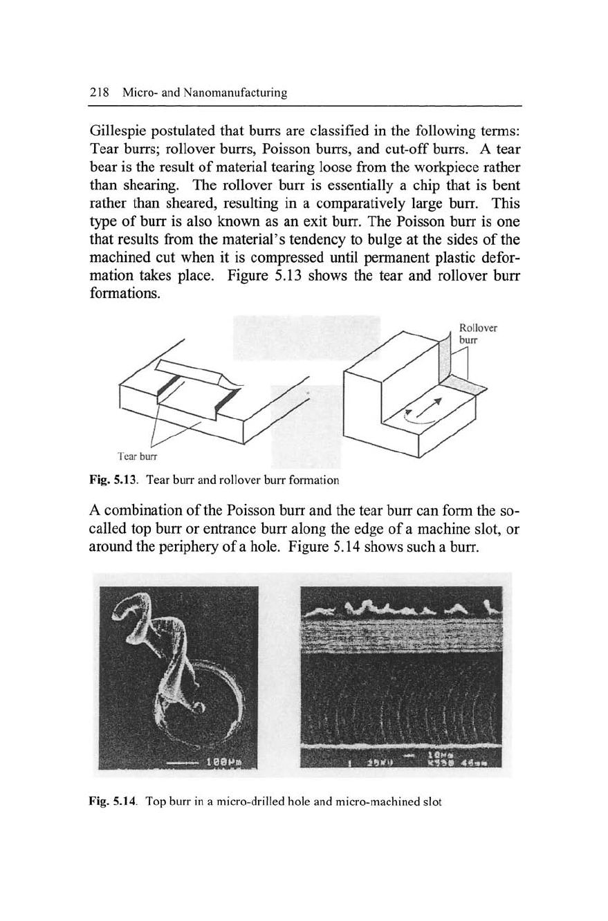
A combination of the Poisson burr and the tear burr can form the so-
called top burr or entrance burr along the edge of a machine slot, or
around the periphery of
a
hole. Figure 5.14 shows such a burr.
Fig. 5.14. Top burr in a micro-drilled hole and micro-machined slot
Mechanical Micromachining 219
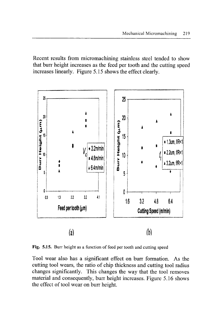
Recent results from micromachining stainless steel tended to show
that burr height increases as the feed per tooth and the cutting speed
increases linearly. Figure 5.15 shows the effect clearly.
£
B
$
*10
L
W
3
ffi
5
0.3
I
1
1
1
' y
1
C
j
•
1
i
k
i
"
ii,i|,
"
vi,ifv
"r
;
^
iLjiMmi
'
1
•' ? i
•3,2m/ni
•4.8m/min
*6,4m/min
—__
3.2
25-
20-
*•*
£
3
N 15-
£
01
! tl
b
1 L
f
3
ffl
Ul
5-
(H
1
A
A
i
1
i
1 '
i
{
f
•
1.3um,f/R<l|
i2.2um,fiR
:
1
*3.2um,f/R>1
1
j |
•-" r i i (
6
3.2 4.8 6,4 |
Cutting Speed (m
/min)
(a)
ft)
Fig. 5.15. Burr height as a function of feed per tooth and cutting speed
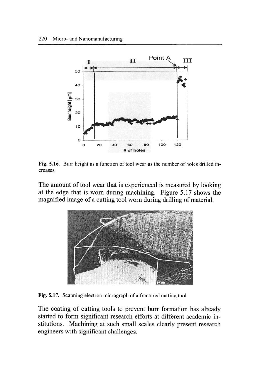
Tool wear also has a significant effect on burr formation. As the
cutting tool wears, the ratio of chip thickness and cutting tool radius
changes significantly. This changes the way that the tool removes
material and consequently, burr height increases. Figure 5.16 shows
the effect of tool wear on burr height.
220 Micro- and Nanomanufacturing
20 40 eO 80 100 120
# of holes
Fig. 5.16. Burr height as a function of tool wear as the number of holes drilled in-
creases
The amount of tool wear that is experienced is measured by looking
at the edge that is worn during machining. Figure 5.17 shows the
magnified image of a cutting tool worn during drilling of material.
Fig. 5.17. Scanning electron micrograph of a fractured cutting tool
The coating of cutting tools to prevent burr formation has already
started to form significant research efforts at different academic in-
stitutions. Machining at such small scales clearly present research
engineers with significant challenges.