Jackson M.J. Micro and Nanomanufacturing
Подождите немного. Документ загружается.

Mechanical Micromachining 201
Where N is the number of
teeth.
Therefore, A is 6.66 |um and the
scallop height is found by using the following:
h
=
7
^— (5.22)
l
td
+
\
7T
J
Therefore h is calculated to be 1.59 x 10"
11
m under the experi-
mental conditions. The scallop height is so small that microscale
channels can be machined with such low surface roughness levels
that the effects of wall friction on fluid flow in the microfluidic
channel are negligible. This allows microfluidic flows to be deter-
mined by geometry of the channel rather than by surface roughness
effects in microfluidic channels. However, surface roughness effects
are significant in nanofluidic channels that can control whether the
liquid flowing in the channel is hydrophilic, or hydrophobic.
5.3.2 Initial Chip Curl Modeling
Chip curvature is a highly significant parameter in micromachining
operations from which a continuous chip is produced. There is a
great deal of uncertainty regarding the mechanism of curly chip
formation and the factors determining the chip radius. Observations
are made on initial chip curl in the simplified case of orthogonal cut-
ting at the micro-and nanoscale. The cutting process may be mod-
eled using a simple primary shear plane and frictional sliding of the
chip along the rake face. When the region of chip and tool interac-
tion at the rake face is treated as a secondary shear zone and the
shear zones are analyzed by means of slip-line field theory, it is pre-
dicted that the chip will curl. Thus chip curvature may be inter-
preted as the consequence of secondary shear. Tight chip curl is usu-
ally associated with conditions of good rake face lubrication [5]. At
the beginning of the cut, a transient tight curl is often observed, the
chip radius increasing as the contact area on the rake face grows to
202 Micro- and Nanomanufacturing
an equilibrium value. Thus it might be suggested that tight curl is an
integral part of the initial deformation.
It has been suggested that the process of continuous chip forma-
tion is not uniquely defined by the boundary conditions in the steady
state and that the radius of curl may depend on the build-up of de-
formation at the beginning of the cut [5]. A treatment of initial chip
curl at the micro-scale curl is now presented, which considers chip
curl as a series of heterogeneous elements in continuous chip forma-
tion at the micro-scale. The free surface of the chip always displays
fine striations, or "lamellae", parallel to the cutting edge. The chip
is usually considered to form by a regular series of discrete shear
events giving a straight chip made up of small parallel segments.
However, no account is taken of the workpiece material that moves
passed the tool between shear events. The following observations
follow on from Doyle, Home, and Tabor's [5] analysis of initial chip
formation.
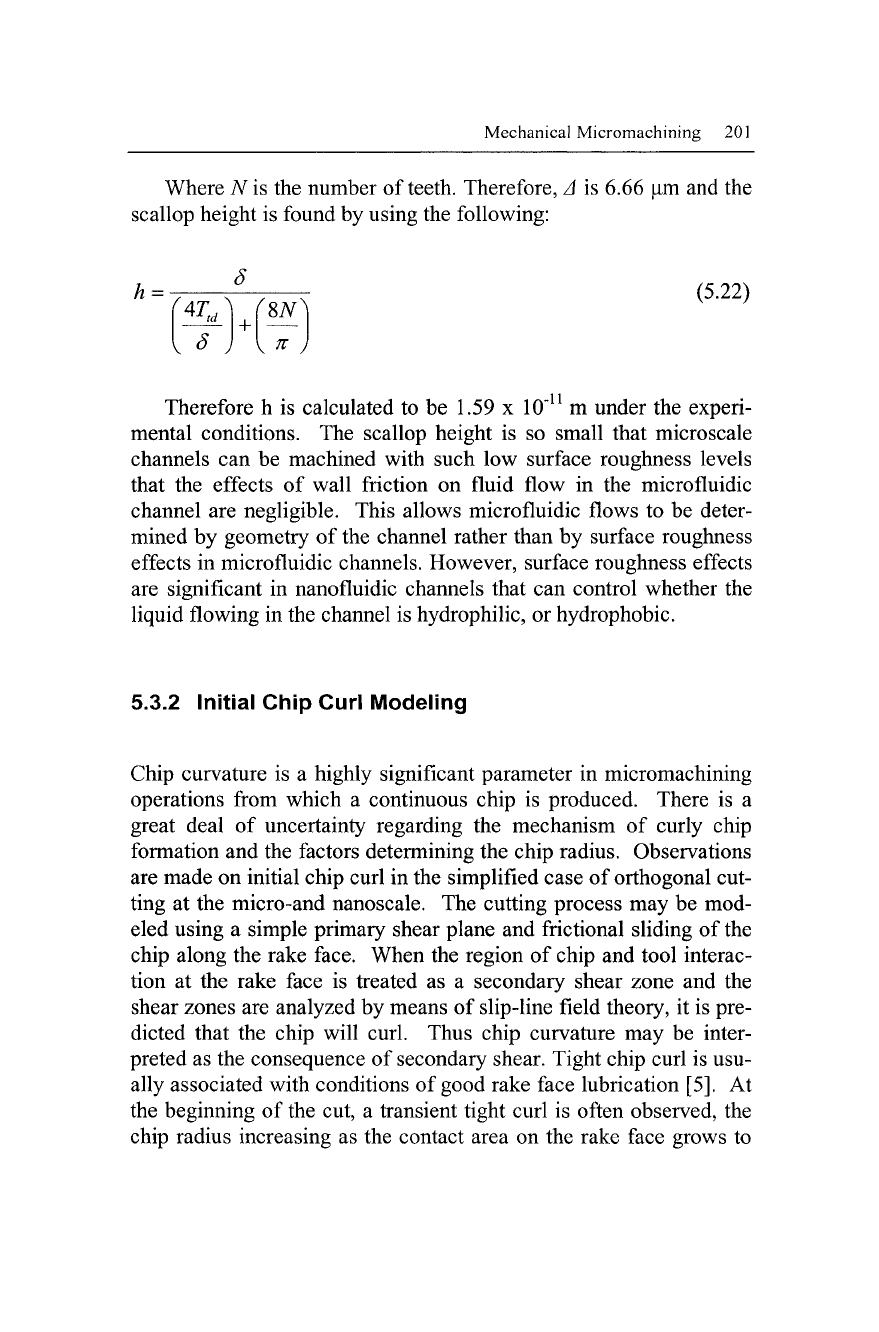
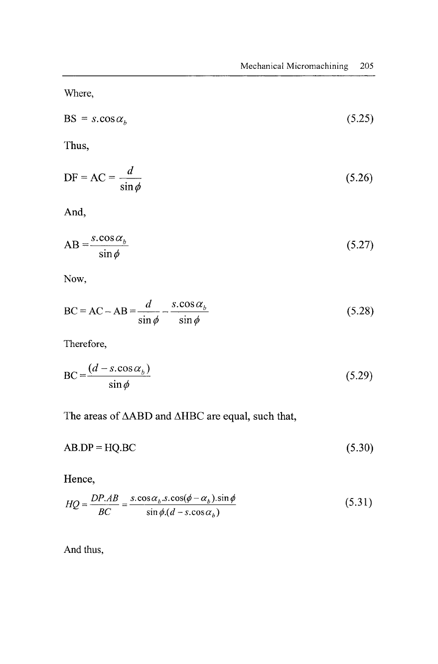
Figure 5.3 shows the instabilities during chip formation that
gives rise to initial chip curl. The shaded range of Fig. 5.3b is the
consequence of
a
built-up edge that very quickly becomes part of the
segmented chips shown in Fig. 5.3d. This "material" provides the
means to curl the chip and as a consequence of this event, the fol-
lowing model is presented. Previous treatments of chip curl analysis
[6] have focused on chip formation with a perfectly stiff cutting tool.
However, during micromachining the cutting tool bends as it ma-
chines the workpiece material [7]. This means that primary chip
curl models must account for deflection of the cutting tool by bend-
ing during an orthogonal micromachining operation. Computational
approaches to modeling chip formation at the micro-and nanoscales
have been attempted in recent years by a number of researchers
[8,9],
who have used a molecular dynamics simulation approach us-
ing stiff cutting tools.
The generation of a transient built-up edge ahead of the cutting
tool between shearing events in a bulging-type of motion generates
the shape of the segment of the metal chip. This is shown in Fig.
5.3c, with the built-up edge forming the "shaded triangle" above the
shear plane. If it is assumed that the built-up edge does not "escape"
under the tool edge, then the areas of the shaded triangles in Figs.
5.3b and 5.3c will be equal. The chip moves away from the rake
Mechanical Micromachining 203
force in a manner shown in Fig. 5.3d. The radius of chip curl can be
calculated by assuming that the built-up edge in transient and that
the element of the "bulged" material contains a small angle relative
to the tool and workpiece.
(a) (b)
(c) (d)
Fig. 5.3. Instability during the formation of a chip during micromachining: (a)
segmented, continuous chip; (b) chip forming instability due to built-up edge; (c)
movement of
a
built-up edge to form a chip; (d) serrated, continuous chip curl
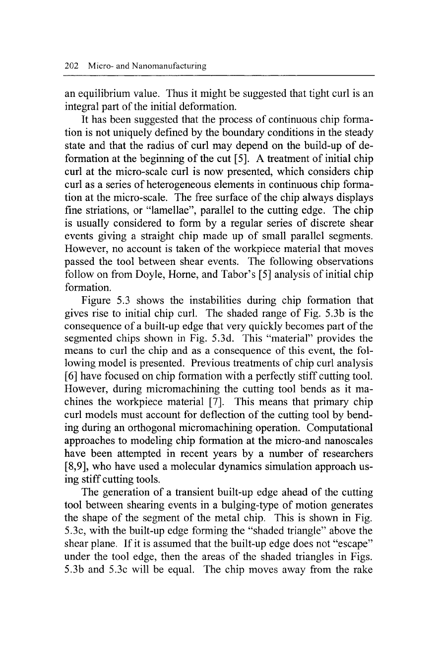
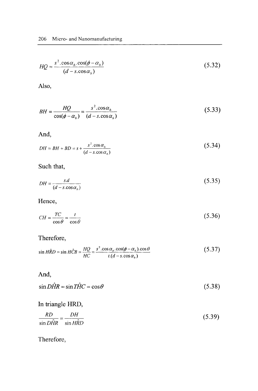
This angle will inevitably change during the bending action of
the cutting tool. With reference to Fig. 5.4, if we assume that the
cutting tool moves from point A to point D then the shear plane AC
rotates to position HC as the built-up edge from triangle ABD is
pushed into the segment of the chip. At point D, the shear along DF
begins and segment DHCF is completed. HC and DF meet at R, the
center of the circle of the chip segment. Since the angle HRD is
small, RD may be referred to as the radius of the chip. The clear-
ance angle is 0.
204 Micro- and Nanomanufacturing
Fig. 5.4. Schematic diagram of the geometry of the primary chip that forms a
curled chip
Triangles ABD and HBC are equal in area and the depth of cut
FG is equal to d. The spacing between the segments, i.e., the lamel-
lae,
is CE, which is equal to BD, which is equal to s. The chip
thickness between lamellae, TC, is equal to t, while the rake angle
SBD is equal to a
•
The cutting tool bends when machining at the
microscale, which reduces the effective rake angle to a
t>-
We know
that the chip radius r can be taken as RD, whilst the shear angle sub-
tended is BAD, or
(j>.
The calculation of the chip radius is provided
by the following analysis:
DP= s.cos{(/)-a
b
) (5.23)
AB = H- (5.24)
sin^
Mechanical Micromachining 205
Where,
BS = s.cosa
b
(5.25)
Thus,
sin^
DF = AC
= -4— (5-26)
And,
AB =—
:
b
- (5.27)
sin^
Now,
BC = AC-AB=-^—^^ (5.28)
sin
(j)
sin
(j)
Therefore,
_ (d -s.cosa,)
BC=-
:
b
— (5.29)
sin^
The areas of
AABD
and AHBC are equal, such that,
AB.DP = HQ.BC (5.30)
Hence,
_
DP.AB
_ sxosa
b
.s.cos{(l)-a
b
).s\ri^ (5 31")
BC sin
<f>.(d
-s.cosa
b
)
And thus,
206 Micro- and Nanomanufacturing
s
2
.
cos a
b
. cos(^
- a
b
)
Also,
HQ =
s .cosa
b
.cos{p-a
b
) (532)
(d -s.cosa
b
)
BH =
H
Q _
s
-
cosa
>
(5.33)
cos{$-a
b
) (d-s.cosa
b
)
And,
s
2
.cos
or,,
DH
=
BH
+
BD
=
s
+ -
Hence,
TC t
CH
= -
COS V COS
C
In triangle HRD,
RD DH
sin DHR sin HRD
(5.34)
(rf-s.cosa
fe
)
Such that,
zw
=
^ (5-35)
(d -s.cosa
b
)
(5.36)
Therefore,
sin HRD = sin
HCB=^
=
^cos^.cos^-aj.cosg (5.37)
WC ?.(rf-i.cosor,,)
And,
sinDik = sin77/C
=
cos6>
(5.38)
(5.39)
Therefore,
Mechanical Micromachining 207
D
r» _ ^jjSinDHR s.d cos
0.t.(d
- s.cos a
b
)
sin HRD (d - s.cos a
b
)
s
2
.cos
a
b
.cos(<f>
- a
b
).cos 6
(5.40)
Thus,
dX
r = (5.41)
s.cosa
b
.cos(<p-a
b
)
If the width of the lamellae, s, is small compared to the chip thick-
ness,
then for continuous machining with a single shear plane,
sM (5.42)
t cos^-or^)
Hence,
t
cos(0-a
b
)
And so,
d
2
V —
s.cos a
b
.
d
sin^
sin^
(5.43)
(5.44)
Equation 5.44 predicts a positive chip radius at negative rake angles.
The approximations considered in this model are appropriate when
one considers that the model assumes that a secondary shear plane
exists.
These models applied at the microscale are highly appropri-
ate because they account for acute bending of the cutting tool that is
not significant at the macroscale. The formation of highly strained
metal chips provides a raw material for the manufacture of
nanocrystalline metal products. This ensures that no waste is gener-
ated during dry milling of microfluidic channels, leading to the de-
velopment of environmentally benign micro-manufacturing proc-
esses.
208 Micro- and Nanomanufacturing
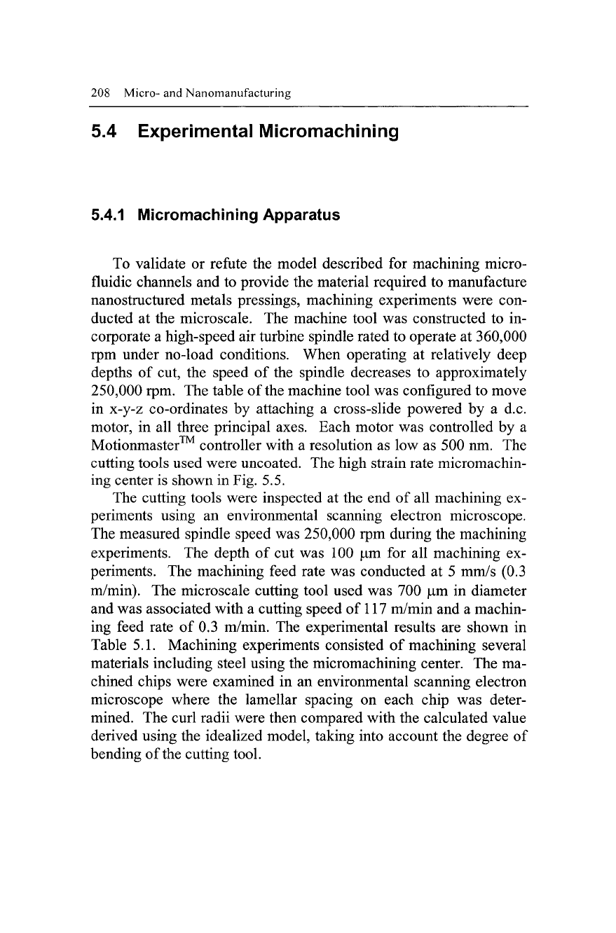
5.4 Experimental Micromachining
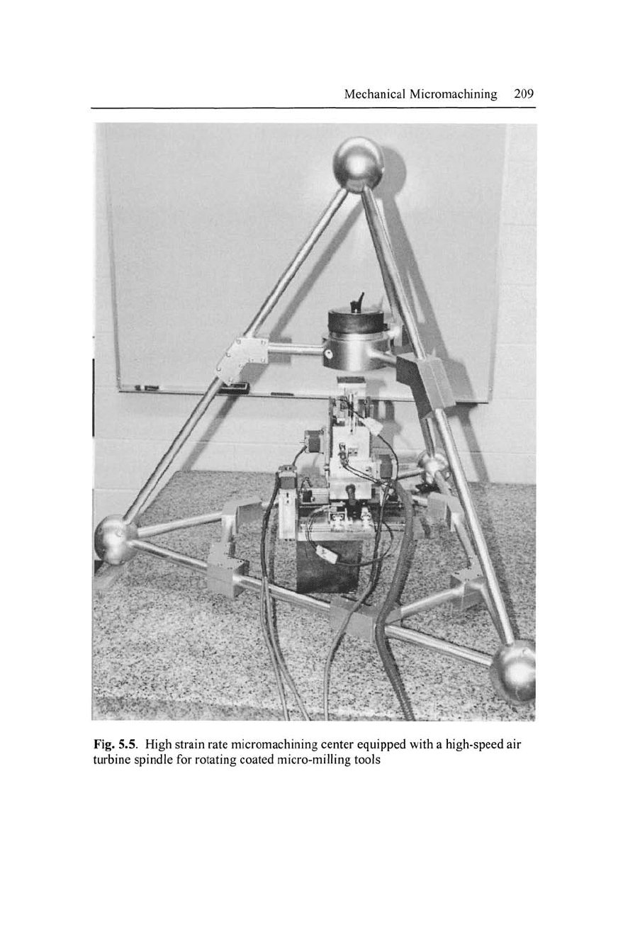
5.4.1 Micromachining Apparatus
To validate or refute the model described for machining micro-
fluidic channels and to provide the material required to manufacture
nanostructured metals pressings, machining experiments were con-
ducted at the microscale. The machine tool was constructed to in-
corporate a high-speed air turbine spindle rated to operate at 360,000
rpm under no-load conditions. When operating at relatively deep
depths of cut, the speed of the spindle decreases to approximately
250,000 rpm. The table of the machine tool was configured to move
in x-y-z co-ordinates by attaching a cross-slide powered by a d.c.
motor, in all three principal axes. Each motor was controlled by a
Motionmaster™ controller with a resolution as low as 500 nm. The
cutting tools used were uncoated. The high strain rate micromachin-
ing center is shown in Fig. 5.5.
The cutting tools were inspected at the end of all machining ex-
periments using an environmental scanning electron microscope.
The measured spindle speed was 250,000 rpm during the machining
experiments. The depth of cut was 100 |um for all machining ex-
periments. The machining feed rate was conducted at 5 mm/s (0.3
m/min). The microscale cutting tool used was 700 |um in diameter
and was associated with a cutting speed of 117 m/min and a machin-
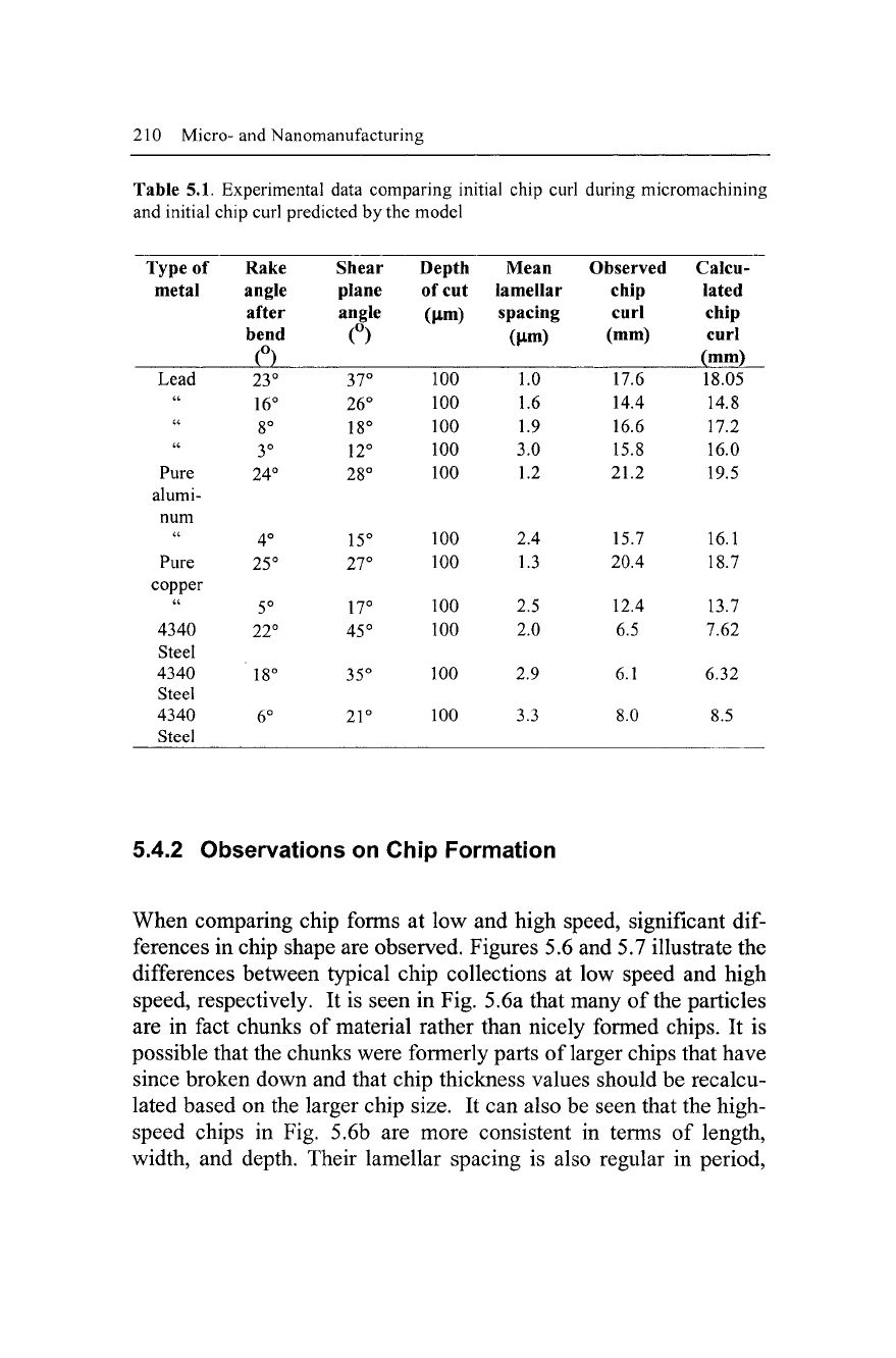
ing feed rate of 0.3 m/min. The experimental results are shown in
Table 5.1. Machining experiments consisted of machining several
materials including steel using the micromachining center. The ma-
chined chips were examined in an environmental scanning electron
microscope where the lamellar spacing on each chip was deter-
mined. The curl radii were then compared with the calculated value
derived using the idealized model, taking into account the degree of
bending of the cutting tool.
Mechanical Micromachining 209
1
.
•i^^H^^HM
\
• •
v
Fig. 5.5. High strain rate micromachining center equipped with a high-speed air
turbine spindle for rotating coated micro-milling tools
210 Micro-and Nanomanufacturing
Table 5.1. Experimental data comparing initial chip curl during micromachining
and initial chip curl predicted by the model
Type of
metal
Lead
"
a
a
Pure
alumi-
num
a
Pure
copper
a
4340
Steel
4340
Steel
4340
Steel
Rake
angle
after
bend
(°)
23°
16°
8°
3°
24°
4°
25°
5°
22°
18°
6°
Shear
plane
angle
<°>
yr
26°
18°
12°
28°
15°
27°
17°
45°
35°
21°
Depth
of cut
(\xm)
ioo
100
100
100
100
100
100
100
100
100
100
Mean
lamellar
spacing
(Jim)
To
1.6
1.9
3.0
1.2
2.4
1.3
2.5
2.0
2.9
3.3
Observed
chip
curl
(mm)
17.6
14.4
16.6
15.8
21.2
15.7
20.4
12.4
6.5
6.1
8.0
Calcu-
lated
chip
curl
(mm)
18.05
14.8
17.2
16.0
19.5
16.1
18.7
13.7
7.62
6.32
8.5
5.4.2 Observations on Chip Formation
When comparing chip forms at low and high speed, significant
dif-
ferences in chip shape are observed. Figures 5.6 and 5.7 illustrate the
differences between typical chip collections at low speed and high
speed, respectively. It is seen in Fig. 5.6a that many of the particles
are in fact chunks of material rather than nicely formed chips. It is
possible that the chunks were formerly parts of larger chips that have
since broken down and that chip thickness values should be recalcu-
lated based on the larger chip size. It can also be seen that the high-
speed chips in Fig. 5.6b are more consistent in terms of length,
width, and depth. Their lamellar spacing is also regular in period,