Ghodssi R., Lin P., MEMS Materials and Processes Handbook
Подождите немного. Документ загружается.

1144 M.A. Huff et al.
for implementing an absolute pressure sensor. Wafer bonding is performed using a
glass frit layer between the two substrates.
From a process integration standpoint, the Freescale pressure sensor example has
several very interesting attributes. First, this technology is highly unusual because
it integrates a bipolar transistor microelectronics process technology with a MEMS
bulk micromachining process technology. The bipolar transistors form amplifiers
that convert the millivolt-level transducer output into a volt-level device output.
Nearly all other MEMS integrated process technologies that have been demonstrated
merge CMOS with MEMS devices.
Second, control over the mechanical dimensions of MEMS devices made using
bulk micromachining are typically not very precise; however, the Freescale tech-
nology employs an electrochemical etch stop that enables precise control of the
membrane thickness which is extremely important for determining the mechanical
stiffness of the pressure sensor membrane (i.e., the amount of membrane deflection
to result from a certain level of pressure loading). This etch stop layer is an epi-
taxially grown n-type layer that is reverse-biased during the etching and when the
etchant solution reaches this layer, the etch terminates. This same epitaxial layer in
the process sequence is also used in the fabrication of the bipolar transistors.
Third, the microelectronics is fabricated first and then the MEMS are subse-
quently made. This is possible inasmuch as all of the MEMS processing steps
subsequent to the microelectronics fabrication are performed at relatively low pro-
cessing temperatures. Fourth, the process uses 100-oriented silicon wafers to enable
the micromachining steps to be done. Normally, 111-oriented wafers are used for the
fabrication of bipolar transistor devices and therefore Freescale needed to develop
a special bipolar transistor process for this substrate orientation. Fifth, the device
wafer can be bonded to another wafer to form a sealed reference cavity for imple-
menting an absolute pressure transducer, or it can be left “as is” to implement a
differential pressure transducer without any major changes to the process sequence.
Lastly, the chrome silicide resistors enable the circuits and sensors to be easily
trimmed for calibration, thereby allowing any offsets to be inexpensively eliminated.
The major disadvantages of this process are that it employs wet anisotropic bulk
micromachining to implement the pressure sensor and therefore a large amount of
die area is consumed by the sidewalls of the exposed crystallographic planes in
the silicon substrate. This is costly compared to the area that would be used to
implement a surface micromachined sensor having the same membrane dimensions.
Also, the wet etch process must expose only the back of the wafer to etchant; this
requires specialized etch fixturing. Lastly, bipolar transistors consume large amounts
of power compared to CMOS electronics and therefore the Freescale integrated
MEMS pressure sensor has higher power consumption levels than some other tech-
nologies. The bipolar circuitry cannot be used to form complex digital circuits, so
this flow is limited to analog devices.
14.8.3.4 Thermal Inkjet Printhead (Xerox)
Thermal inkjet (TIJ) technology has emerged as the choice for low-cost desktop
printing since the PC era in 1980s [75–77]. Typical TIJ printheads are used as
14 MEMS Process Integration 1145
drop-on-demand printheads; that is, the ink is ejected from the nozzle only when
there is a demand for an image on the paper. The printhead is operated by applying
a short pulse (several microseconds) to the heater plates inside the nozzles. The ink
in contact with the heater surface rapidly heats up and a vapor bubble is generated.
This creates a great volume expansion (about 50 times) of the heated liquid and a
pressure of about 100 atmospheres that is sufficient to eject the ink from the nozzles
at a high velocity 5–10 m/s. By about 30 µs after the initial voltage pulse, the drops
break off at the nozzles and the bubbles collapse back onto the heater. The ink then
refills the channels from the ink reservoir through capillarity and the meniscus at
the nozzle settles to the original state before the next drop is ejected. The refilling
process typically takes on the order of 100 µs and is determined by the fluid dynam-
ics and channel geometry. TIJ is also called bubble jet because it uses the bubble to
force out the ink.
Canon, HP, and Xerox are three of the first companies that integrated MEMS
with IC to manufacture the TIJ printheads. Attributed to the disposable ink car-
tridge packaging, it is by far the largest volume of MEMS chips ever produced.
MEMS structures are created as the ink channels, reservoir, and nozzles, whereas
the IC is the control of the demand of power to generate the thermal bubble. In addi-
tion to other examples of integrated MEMS described elsewhere in this chapter, TIJ
printheads have many unique integration issues. First, ink fluid is relatively corro-
sive to many metals used in IC production. Second, the heat from the heater needs
to be isolated from the temperature-sensitive microelectronics. A metal heat sink is
commonly used in contact with the heater substrate. Third, the packaging of the inte-
grated MEMS inkjet chips needs to be compatible with the ink chemistry. Fourth,
the ink nozzle requires hydrophobic treatments to keep the nozzle clean from ink
accumulation. The hydrophobic treatment can be done by solution or vapor phase
coating on the nozzle surface. It is desired to keep this coating only on the outer
surface of the nozzle and to keep hydrophilic surfaces inside the nozzle and ink
channel. Lastly, the nozzle area needs to be flat after packaging and accessible by
the printing media within the distance of a few hundred micrometers. The examples
below describe the fabrication processes of the chamber wafer, heater wafer, and the
bonding of these two wafers.
There are a couple of major designs for TIJ printheads [75].Oneiscalledan
edgeshooter where the droplets are propelled along trajectories that are parallel to
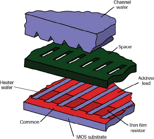
the heating element surfaces. A typical edgeshooter design is shown in Fig. 14.79,
which consists of a silicon channel wafer bonded to a heater wafer with a polyimide
spacer layer [78]. The heater wafer is the silicon substrate with the array of hearing
elements, logic circuits, and addressing electrodes. On the top surface of the heater
wafer, a patterned thick polymeric layer such as polyimide is used to form the ink
flow paths. A linear array of parallel grooves is formed on the channel wafer. One
end of the grooves connects with the ink inlet manifold and the other end is open to
form ink nozzles. A typical inkjet die is less than 1 in. in length and contains several
hundreds nozzles. A 600 nozzles-per-inch printhead would have a pitch of about 42
µm which includes the nozzle width and the thickness of the wall between nozzles.
The other design is called a roofshooter where the ink is ejected in the direction
perpendicular to the heater surface. The roofshooter design can be done similarly
1146 M.A. Huff et al.
Fig. 14.79 Thermal inkjet printheads made of three components: channel wafer, spacer layer, and
heater wafer [78] (Reprinted with permission, copyright 1997 IEEE)
with the nozzles open on the surface of the silicon channel wafer, rather than on
the edge of the wafer. Another popular roofshooter design is to replace the silicon
channel wafer with a flexible polyimide nozzle substrate and to have ink channels
and fill holes anisotropically etched through the silicon heater wafer. The following
section focuses on the design and fabrication of the edgeshooter printhead.
Heater Wafer
The heater wafer is produced from typical IC processes [79, 80]. It contains a linear
array of heaters and MOS circuits that control ink ejection. Unlike the prediction
of Moore’s law, the IC for TIJ printhead is not state of the art compared to the
current 45 nm technology. This is partly due to the low switching speed and high
current/power requirements. To save cost, typical manufacturing foundries used for
inkjet are those with excess capacity in the small wafer sizes such as 6 or 8 in.
foundries. It is also common practice to reduce the packaging cost by integrating
addressing and multiplexing logic on the heater wafer to minimize the number of
external connections [81].
Although the heater wafer can be fabricated using most IC processes, several spe-
cial fabrication steps are required [81]. One possible material choice for the heater
is the polysilicon. Without protection, polysilicon lifetime is very limited due to the
high pressure of the collapsing bubble (i.e., cavitations) and the corrosive property
of the ink. A t antalum layer is deposited over the polysilicon heater for protection.
14 MEMS Process Integration 1147
An insulating silicon nitride layer is usually placed between the polysilicon and tan-
talum to prevent a potential being applied to the tantalum surface in contact with the
ink, which would cause electrolysis of the ink. The silicon nitride should be as t hin
as possible, consistent with absence of pinholes (about 50–150 nm). In addition, to
achieve thermal efficiency, a thicker than usual field oxide is deposited to reduce the
thermal losses to the silicon substrate. All MOS circuits are covered by polyimide
to prevent exposure to the corrosive ink.
Channel Wafer
The channel wafer is mainly the mechanical and fluidic structures of the ink channel,
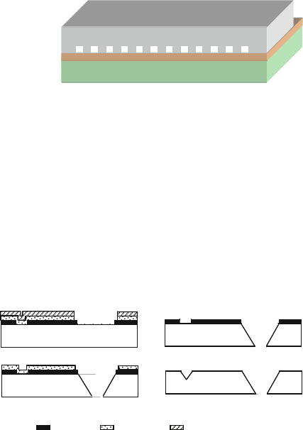
reservoir, and nozzles and contains no integrated circuits. As shown in Fig. 14.79,
the nozzle has a triangular shape created by anisotropic etching in KOH solution on
the single crystalline silicon. As shown in Fig. 14.80, the nozzle can also have a rect-
angular shape created by ICP RIE etching. The advantages of anisotropic etching
are the low cost and ease of the etch depth control. A rectangular shape offers more
nozzle numbers per area and higher print resolution, but controlling the variation in
etch depth is a challenge.
Heater wafer
Channel Wafer
Fig. 14.80 Nozzle with
rectangle shape for TIJ
printheads [82] (Reprinted
with permission, copyright
2004, IEEE)
It is often very desirable to have multiple etch depths in the channel wafer to
control the ink ejection and refill process. With multiple masks, one can achieve
different etch depths on the same wafer. It would be very difficult to handle wafers
and perform precision lithography after deep etching, therefore it is recommended to
pattern all the masking layers before the first KOH etching. Figure 14.81 shows the
process of a two-mask channel wafer [76]. Silicon oxide serves as the ink channel
mask and the silicon nitride layer serves as the masking layer for the ink i nlet. The
first step is to deposit silicon oxide and polysilicon as the masking layers for ink
channels. The polysilicon layer provides scratch protection during wafer handling.
: SiO
2
: Si
3
N
4
: Poly Si
(a)
(b)
(c)
(d)
Fig. 14.81 Process of
making channel wafers with
triangle-shaped nozzle
1148 M.A. Huff et al.
After patterning the first mask on both polysilicon and silicon oxide, polysilicon is
stripped and the second masking layer (silicon nitride and polysilicon) is deposited
(Fig. 14.81a). After patterning the second masks on polysilicon and silicon nitride,
wet etching in KOH is carried out (Fig. 14.81b). Polysilicon is etched away during
the KOH etching and silicon nitride is removed using H
3
PO
4
solution after etching
(Fig. 14.81c). The silicon oxide is removed after forming the ink channels by t he
second KOH etching (Fig. 14.81d).
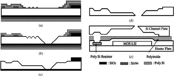
Figure 14.82 shows a more complicated design in channel wafers containing an
ink inlet and ink chamber (by KOH etching) and ink nozzle (by dry RIE etching)
[82]. Figure 14.82a shows that four masks are used to pattern the masking layers for
two KOH etching (silicon nitride), one protection layer (polysilicon) and one RIE
etching (silicon oxide). The first KOH etching forms the ink inlet and the silicon
nitride is removed using a H
3
PO
4
solution after etching (Fig. 14.82b). Polysilicon is
patterned between two silicon nitride layers to protect the lower silicon nitride from
the first KOH etching. The second KOH etching is a shorter duration than the first
one to form the ink channels between the ink inlet and the ink nozzles. After KOH
etching, the silicon nitride is also removed using H
3
PO
4
solution (Fig. 14.82c).
Silicon oxide is used as the masking material for the nozzles and is removed using
an HF solution (Fig. 14.82d). The channel wafer is then ready to bond to the heater
wafer (Fig. 14.82e).
Fig. 14.82 Fabrication process of channel wafers with rectangle-shaped nozzle [82] (Reprinted
with permission, copyright 2004, IEEE)
Polyimide and Packaging
The polyimide layer serves several functions. First, it creates a recess pit for the
heater area, which helps confine the area for the bubble. Second, it creates a smooth
surface on the heater wafer for better bonding. The polyimide surface is planarized
using chemical mechanical polishing after patterning. Third, polyimide is also part
of the ink channels that connect the ink nozzles and ink inlet. The ink flow resistance
14 MEMS Process Integration 1149
can be fine-tuned by the polyimide pattern. Fourth, the polyimide on the heater wafer
during dicing can protect the electronics from the silicon debris thrown off from the
dicing blade. The small silicon shards can penetrate the passivation oxide and short
out the underlying electronics. Finally, it serves as a cushion layer during the dicing.
After wafer bonding, a half-way dicing cut is needed to cut the channel wafer only,
not the heater wafer in order to expose the bond pads on the heater wafer. Typical
polyimide thickness is about 15–50 µm.
The heater wafer and the channel wafer are bonded together using polymeric
adhesives (such as EPON
TM
epoxy resin) and the infrared aligning tool [83]. During
bonding, the polymeric adhesives may be adversely squeezed out of the contact
areas under the pressure and heat, and spilled into the channels causing the blocking
of the ink channels. To avoid this problem, a thin film of adhesive is first uniformly
coated on an intermediate carrier substrate and then transferred onto the channel
wafer for bonding. This adhesive transferring process can reduce the adhesive thick-
ness to less than 2 µm and eliminate the blocking problem. The adhesive is cured
under pressure at a temperature less than 200
◦
C. Another method to bond the heater
and channel wafers through the polyimide layer is electrostatic bonding by apply-
ing 1 kg/cm
2
clamping pressure and 100 V at 350
◦
C (see Section 4.3.2.3 for more
details).
Similar to the LED bar used in scanners, multiple TIJ chips can be butted together
to make a long printhead, usually called a full width array. It has a full width of
regular paper size such as 8.5 in. or larger. This is unique for TIJ MEMS chips
inasmuch as most MEMS devices contain only one die in the system. A typical TIJ
die length is less than 1 in. Thus, it would take about a dozen die to make a full width
array printhead. The main advantage of a full width array is the increase of printing
speed. The challenges of a full width array are the precision of dicing required for
butting the die with less than 20 µm variation, the complex connection to the ink
supply, and the required fast drying of the large amount of ink deposited on the print
in a relatively short time.
Chip warping is a common problem for wafer bonding due to mismatch in the
thermal expansion coefficients. By combining low temperature bonding and the
same thermal expansion coefficients for both plates, chips longer than 1 in. can
be produced in this design without much warping.
14.8.3.5 Microbolometer (Honeywell)
The uncooled MEMS microbolometer technology has been a revolution in long-
wavelength infrared (LWIR) sensing applications [84]. LWIR is the infrared band
from about 8 to 14 µm and coincides with an atmospheric window. Up to the time of
this invention, infrared focal plane arrays (i.e., imager die composed of an array of
pixels) were implemented using small bandgap semiconductors, such as mercury–
cadmium–telluride (HgCdTe), which required that these sensors be continuously
cooled to liquid nitrogen temperatures to prevent the incoming signal from being
swamped out by thermally generated charge carriers. The requirement of refrig-
eration combined with a very expensive fabrication process to merge these exotic
1150 M.A. Huff et al.
semiconductors with integrated circuits for readout electronics meant that the cost
of these infrared imagers was very high and also susceptible to failure mechanisms.
Nevertheless, these cooled IR detectors have been extensively used for military
applications where the ability to see in the dark is critical.
Using micromachining technology to create thermally isolated structures that
simultaneously possess low thermal capacitance, have allowed uncooled infrared
sensors to be demonstrated having noise equivalent delta temperatures (NEDTs) of
40 mK or better, which is a performance level that many thought was possible only
with a cooled approach [84–86].
In the 1980s and 1990s, two companies pioneered the development of uncooled
MEMS infrared devices. One of these companies was Texas Instruments, who devel-
oped a pyroelectric-based sensing scheme and the second was Honeywell, who
developed a microbolometer approach. The Honeywell approach has been licensed
to a number of companies who are producing focal plane array imager die for
military, police, fire, and industrial applications. The basic mechanism by which
the Honeywell microbolometer works is quite simple. Incoming infrared radiation
is absorbed by a microstructure element (i.e., a detector pixel) and this absorbed
radiation causes the microstructure to heat up. Contained within the microstruc-
ture element is a metal resistor that changes resistance as the temperature of
the resistor changes. The key to the high performance of the microbolometer is
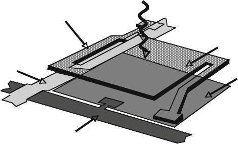
that (1) the microstructure is thermally isolated from the substrate (Fig. 14.83),
(2) the microstructure has a small thermal capacitance, and (3) the response of the
temperature-sensitive resistor within the microstructure is very high. Specifically,
the pixel temperature increases by a measurable amount even when the incoming
infrared radiation is very small in magnitude. This is made possible by the high level
of thermal isolation that is achieved in the microstructure. Also important is that the
temperature of the microstructure changes relatively quickly as incoming infrared
energy changes. This is made possible by the low thermal time constant of the
Thermal Isolation Supports
Incoming Infrared Radiation
Substrate with Integrated
Electronics
Metal Interconnect
Cross-Over
Metal Inteconnect
Suspended Pixel Composed
of SiN and Vanadium Oxide
Fig. 14.83 Bolometer pixel that stands above the substrate t o achieve thermal isolation
14 MEMS Process Integration 1151
microstructure which is in turn made possible by the small thermal capacitance of
the microstructure. Lastly, the transduction mechanism (how the incoming infrared
energy is converted into an electrical signal) must be large. The microbolometer
uses a resistor material (e.g., vanadium oxide (VOx) that has a very high temper-
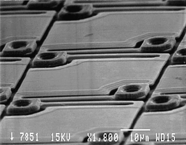
ature coefficient of resistance (TCR) value [84–86]. Figure 14.84 is a SEM of a
section of a focal plane array of microbolometer devices.
Fig. 14.84 SEM image of
array of microbolometers
(Reprinted with permission,
copyright Honeywell
International, Inc.)
Achieving the high performances demonstrated in the microbolometer is only
made possible with MEMS technology. We review the process sequence used to pro-
duce the Honeywell microbolometer in order to demonstrate the benefits of MEMS
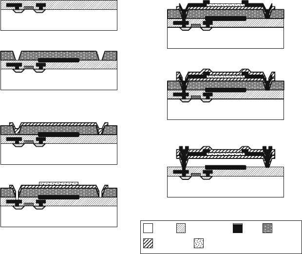
fabrication (Fig. 14.85).
The fabrication of the microbolometers is an integrated MEMS process tech-
nology because it combines a large array of MEMS sensors on a microelectronics
wafer. The first part of the fabrication of the microbolometers begins with a CMOS
process sequence to implement the pixel readout and biasing electronics [84–86].
The microelectronics process includes those steps to implement the metallization
interconnects for the devices. The MEMS is then fabricated on the surface of the
CMOS wafer using low-temperature and processing steps chemically compatible
to the microelectronics (Fig. 14.85). The desire for a high fill-factor focal plane
array is a very important design consideration that drives an integrated MEMS
process technology approach. The microbolometer fabrication is best classified as
a “MEMS last” integration process technology. A number of different microelec-
tronics foundry processes can be used so this portion of the process can be easily
outsourced.
The CMOS starting wafer is suitably planarized (Fig. 14.85a). Next, the surface
of the wafer is coated with a thin reflective material that is subsequently patterned
to leave this material so that it will be located under the suspended microstructure
pixels (Fig. 14.85b). A polymer material is then spin deposited onto the surface
of the wafer. This polymer will act as a sacrificial layer during fabrication and will
allow the microstructure to achieve excellent thermal isolation. The thickness of this
layer is chosen to be 2.5 µm, which determines the gap between the microstructure
1152 M.A. Huff et al.
Silicon Wafer
(a). Starting substrate is a CMOS wafer that has been
suitably planarized.
(d). Vanadium oxide is sputter deposited and patterned
using lift-off followed by the deposition of a silicon nitride
layer (not shown). Vias are then patterned and etched
throu
g
h the silicon nitride and CMOS dielectric la
y
ers.
Silicon Wafer
(b). A thin reflective material is deposited and patterned
where the thermally-isolated IR pixel will be located and
then a sacrificial layer of polymer is deposited and
patterned to open vias through polymer layer.
Silicon Wafer
(c). A bottom silicon nitride layer is patterned and etched.
Silicon Wafer
(e). Metal is deposited and patterned and etched to form
electrical connections to the VOx layer.
Silicon Wafer
(f). Silicon nitride is deposited, patterned and etched to form
top of infrared microstructure.
Silicon Wafer
(g). Metal contacts are made and the microstructure is
released by removing the sacrificial polymer layer.
Silicon Wafer
Silicon
CMOS Dielectric
Silicon Nitride
Metal
Vanadium Oxide
Polymer
Fig. 14.85 Process sequence for fabrication of the infrared sensing microbolometer
sensor and the substrate surface. This gap spacing is driven by the desire to create
an optically resonant cavity that is tuned to the middle of the 8–14 µminfrared
bandwidth. The reflective material on the surface combined with the creation of an
optical resonate cavity allows the absorption over the desired infrared band to be
maximized at over 80%, even when the microstructure is less than 1 µm in total
thickness.
Photolithography is then performed to pattern the polymer sacrificial layer into
mesas that are located on the wafer surface where the pixels will be fabricated
(Fig. 14.85b). Next, a thin layer of silicon nitride is sputtered onto the wafer to create
the bottom layer of the suspended microstructure. Photolithography is performed to
pattern the silicon nitride layer which is then etched using RIE (Fig. 14.85c). A layer
of vanadium oxide (VOx) is then deposited by sputtering and photolithography is
performed to pattern this layer. After the vanadium oxide layer has been etched,
vias are made though the bottom silicon nitride and the CMOS dielectric layers in
order to make electrical contact to the underlying CMOS electronics (Fig. 14.85d).
A layer of metal is deposited, patterned, and etched to make electrical connection
to the VOx sensors (Fig. 14.85e). Another layer of silicon nitride is then sputter
deposited. This layer of silicon nitride will create the top layer of the microstruc-
ture. Photolithography is performed to pattern the silicon nitride layer, which is then
14 MEMS Process Integration 1153
etched using RIE (Fig. 14.85f). Lastly, metal contacts are made to the devices and
then the sacrificial layer of polymer is removed by exposing the wafer to an oxygen
plasma etch to release the microstructure (Fig. 14.85g).
14.8.3.6 ASIMPS and ASIM-X (CMU)
The Application-Specific Integrated MEMS Processing Service (ASIMPS) and the
closely r elated Application-Specific Integrated MEMS-Exchange (ASIM-X) are
process technologies developed at Carnegie Mellon University that use microma-
chining on CMOS wafers produced on a commercial foundry IC process to make
micromechanical devices integrated with microelectronics [87, 88]. The ASIMPS
process uses the CMOS interconnect layers as the micromechanical material.
We describe the ASIM-X process technology, which is similar to ASIMPS but
incorporates bulk silicon under the CMOS interconnect layers to make relatively
thick single-crystal silicon micromechanical devices. The commercial foundry pro-
cesses that have been used in the ASIM-X process technology include: the Jazz
Semiconductor 4-layer metal 0.35 µm SiGe60 BiCMOS; the Taiwan Semiconductor
Manufacturing Company (TSMC) 4-layer metal 0.35 µm CMOS; and the IBM
5HPE SiGe BiCMOS using a 4-layer metal 0.35 µm linewidth CMOS. The ASIM-X
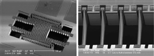
process has found application for the implementation of resonators, inertial sensors,
optical elements, and many other MEMS devices (See Fig. 14.86).
The ASIM-X process begins with the fabrication of the microelectronics at
a commercial foundry (Fig. 14.87a)[87]. Upon receipt, the substrates are then
mounted onto a handle wafer with the topside down using a resist layer as an
adhesive.
Photoresist is then deposited on the CMOS substrate and photolithography is per-
formed (Fig. 14.87b). Subsequently, a timed backside DRIE is performed through
most of the thickness of the CMOS substrate leaving a single-crystal silicon layer
of approximately 50 µm (Fig. 14.87c).
Next, a timed isotropic silicon etch is performed using xenon di-fluoride (XeF
2
)
as seen in Fig. 14.87d. The CMOS substrate is then debonded from the handle wafer
Fig. 14.86 SEM images of integrated MEMS devices implemented using CMU ASIMPS or
ASIM-X process technologies. Device shown in left image is an integrated inertial sensor and
device shown on right is a series of integrated micromechanical resonators (Reprinted with
permission, copyright Prof. Gary Fedder at Carnegie Mellon University)
