Fitzgerald A.E. Electric Machinery
Подождите немного. Документ загружается.

536 CHAPTER 10 Introduction to Power Electronics
It is a relatively straightforward matter to show that maximum output voltage of
this bridge configuration will occur when the SCRs are turned ON at the times when
the diodes in a diode bridge would naturally turn ON. These times can be found from
Table 10.1. For example, we see that SCR T5 must be turned ON at angle C~d = 0
(i.e., at the positive zero crossing of Vab(t)). Similarly, SCR T1 must be turned ON at
time C~d = Jr/3, and so on.
Thus, one possible scheme for generating the SCR gate pulses is to use the
positive-going zero crossing of Vab(t) as a reference from which to synchronize a
pulse train running at six times the fundamental frequency (i.e., there will be six
uniformly-spaced pulses in each cycle of the applied voltage). SCR T5 would be fired
first, followed by SCRs T1, T6, T2, T4, and T3 in that order, each separated by 60 °
in phase delay.
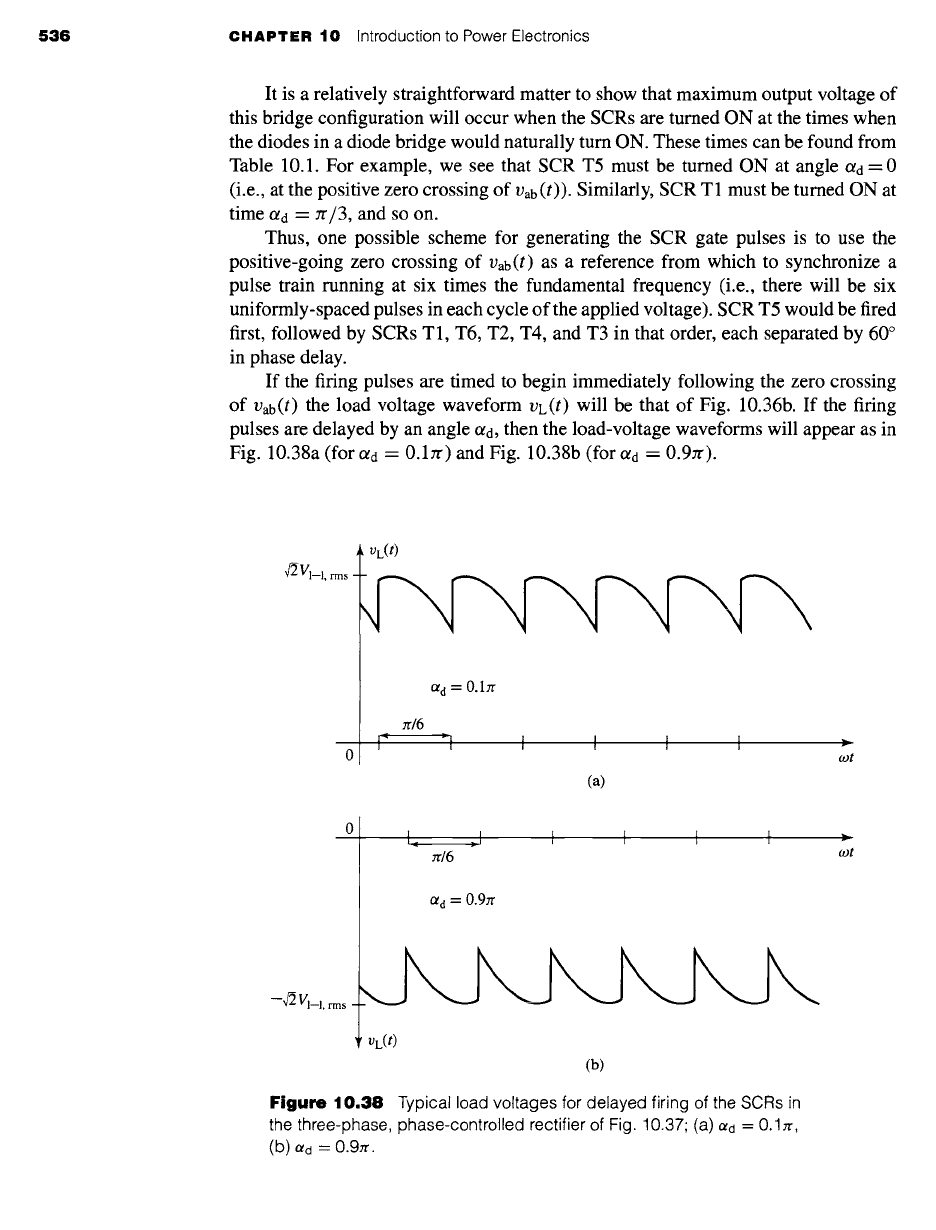
If the firing pulses are timed to begin immediately following the zero crossing
of Vab(t) the load voltage waveform VL(t) will be that of Fig. 10.36b. If the firing
pulses are delayed by an angle Otd, then the load-voltage waveforms will appear as in
Fig. 10.38a (for Ctd = 0.1zr) and Fig. 10.38b (for Ctd = 0.9zr).
rr/6
Ctd = O.17r
I ~ -~1 I I I I
(a)
r
cot
O~ d =
0.9rr
(b)
Figure 10.38
Typical load voltages for delayed firing of the SCRs
in
the three-phase, phase-controlled rectifier of Fig. 10.37 (a) Otd = 0.1rr,
(b) Re -" 0.97f.
zr/6 wt
10.2
Rectification: Conversion of AC to DC
537
The dc average of the output voltage of the phase-controlled bridge can be
found as
gdc ~
309 -j~ ~l+rr/3to
--Vbc (t)
dt
to
a d +z/3
3w
~/2 ~-l,rms sin
cot d t
zc 3
to
-- (3-~) Vl-l,rms cos Otd
(0 < ot~ < Jr) (10.20)
where
gl-l,rms
is the rms value of the line-to-line voltage.
A large magnet with an inductance of 14.7 H and resistance of 68 f2 is to be supplied from
a 60-Hz, 460-V, three-phase source through a phase-controlled SCR bridge as in Fig. 10.37.
Calculate (a) the maximum dc voltage
V d ....
and current ld
.....
which can be supplied from
this source and (b) the delay angle 0td required to achieve a magnet current of 2.5 A.
II
Solution
a. From Eq. 10.20, the maximum voltage (corresponding to c~d = 0) is equal to
Vd .... = ~ Vl-l,rms= ~ 460=621V
Jr
and Id
..... -- Wd ..... /R
= 9.1 A
b. The delay angle for a current of 2.5 A, corresponding to Vdc = /de R = 170 V, can be
found from inverting Eq. 10.20 as
Vl-l,rms = 1.29 rad = 74.1 °
EXAMPLE 10.9
Repeat Example 10.9 for the case in which the 60-Hz source is replaced by a 50-Hz, 400-V,
three-phase source.
Solution
a. Va
.... -"
540 V, Ia
..... =
7.94 V
b. ota = 1.25 rad = 71.6 °
The derivations for three-phase bridges presented here have ignored issues such as
the effect of commutating inductance, which we considered during our examination
of single-phase rectifiers. Although the limited scope of our presentation does not
538 CHAPTER 10 Introduction to Power Electronics
permit us to specifically discuss them here, the effects in three-phase rectifiers are
similar to those for single-phase systems and must be considered in the design and
analysis of practical three-phase rectifier systems.
10.3 INVERSION: CONVERSION OF DC TO AC
In Section 10.2 we discussed various rectifier configurations that can be used to
convert ac to dc. In this section, we will discuss some circuit configurations, referred
to as
inverters,
which can be used to convert dc to the variable-frequency, variable-
voltage power required for many motor-drive applications. Many such configurations
~nd techniques are available, and we will not attempt to discuss them all. Rather,
consistent with the aims of this chapter, we will review some of the common inverter
configurations and highlight their basic features and characteristics.
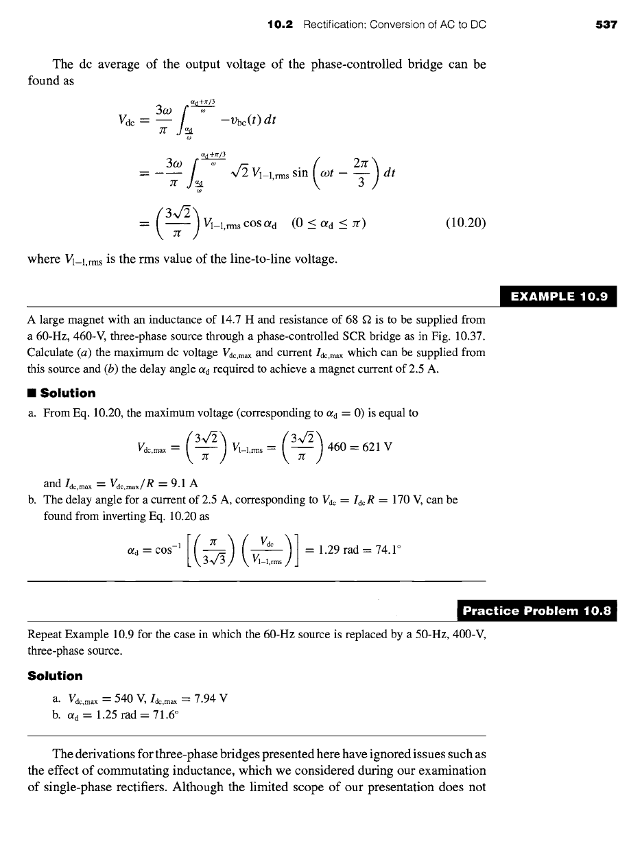
For the purposes of this discussion, we will assume the inverter is preceded by a
"stiff" dc source. For example, in Section 10.2, we saw how an LC filter can be used
to produce a relatively constant dc output voltage from a rectifier. Thus, as shown
in Fig. 10.39a, for our study of inverters we will represent such rectifier systems by
a constant dc voltage source V0, known as the
dc bus voltage
at the inverter input.
We will refer to such a system, with a constant-dc input voltage, as a
voltage-source
inverter.
Similarly, we saw that a "large" inductor in series with the rectifier output pro-
duces a relatively constant dc current, known as the
dc link current.
We will therefore
+
Vs(t)
L
0
L +
+1
c i_ =
0
+
v~(t)
Io
Ca)
I. /o
t
(b)
Figure 10.39
Inverter-input representations. (a) Voltage source.
(b) Current source.
10.3 Inversion: Conversion
of DC to AC 539
represent such a rectifier system by a current source I0 at the inverter input. We will
refer to this type of inverter as a
current-source inverter.
Note that, as we have seen in Section 10.2, the values of these dc sources can be
varied by appropriate controls applied to the rectifier stage, such as the timing of gate
pulses to SCRs in the rectifier bridge. Control of the magnitude of these sources in
conjunction with controls applied to the inverter stage provides the flexibility required
to produce a wide variety of output waveforms for various motor-drive applications.
10.3.1 Single.Phase, H-bridge Step-Waveform Inverters
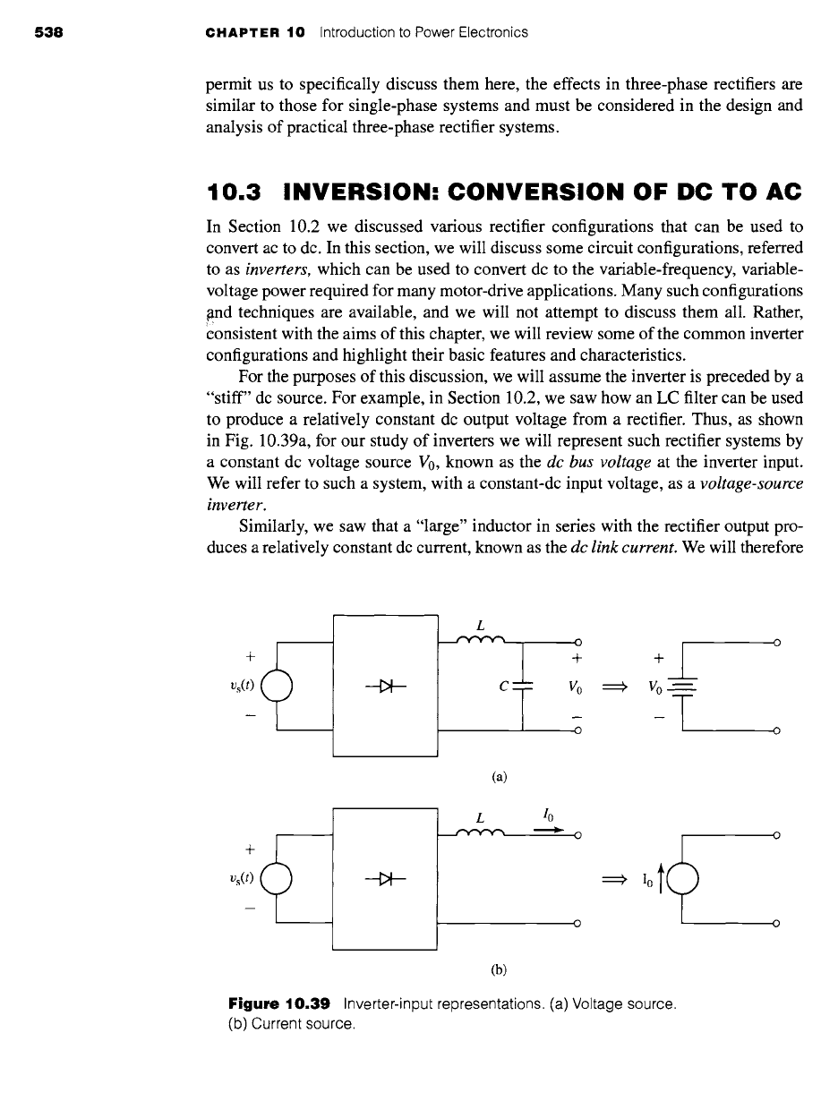
Figure 10.40a shows a single-phase inverter configuration in which a load (consisting
here of a series
RL
combination) is fed from a dc voltage source V0 through a set of
four IGBTs in what is referred to as an
H-bridge
configuration. MOSFETs or other
switching devices are equally applicable to this configuration. As we discussed in
Section 10.1.3, the IGBTs in this system are used simply as switches. Because the
IGBTs in this H-bridge include protection diodes, we can analyze the performance
of this circuit by replacing the IGBTs by the ideal-switch model of Fig. 10.13b as
shown in Fig. 10.40b.
For our analysis of this inverter, we will assume that the switching times of this
inverter (i.e., the length of time the switches remain in a constant state) are much longer
than the load time constant L/R. Hence, on the time scale of interest, the load current
will simply be equal to
VL/R,
with VL being determined by the state of the switches.
Let us begin our investigation of this inverter configuration assuming that switches
S1 and $3 are ON and that iL is positive, as shown in Fig. 10.41a. Under this condition
the load voltage is equal to V0 and the load current is thus equal to
Vo/R.
Let us next assume that switch S1 is turned OFF, while $3 remains ON. This
will cause the load current, which cannot change instantaneously due to the presence
of the inductor, to commutate from switch S 1 to diode D2, as shown in Fig. 10.4 lb.
Note that under this condition, the load voltage is zero and hence there will be zero
load current. Note also that this same condition could have been reached by turning
switch $3 OFF with S 1 remaining ON.
m
m
iL(t) R L
+ VL(t)
--
~4-~ D4
.3--~D 3
+
v0
I LD I J_
Sl2~/L_~(t) R L S4~ D4
(a) (b)
Figure 10.40
Single-phase H-bridge inverter configuration. (a) Typical configuration using IGBTs. (b) Generic
configuration using ideal switches.
540
CHAPTER 10 Introduction to Power Electronics
+1
Vo~
-T
"1-"
VL(t ) --
D2
R L
iL(t) )
2.~ D4
+
Vo m
D12
(a)
(b)
Jr- VL(t ) -- 2
R L
.~ D4
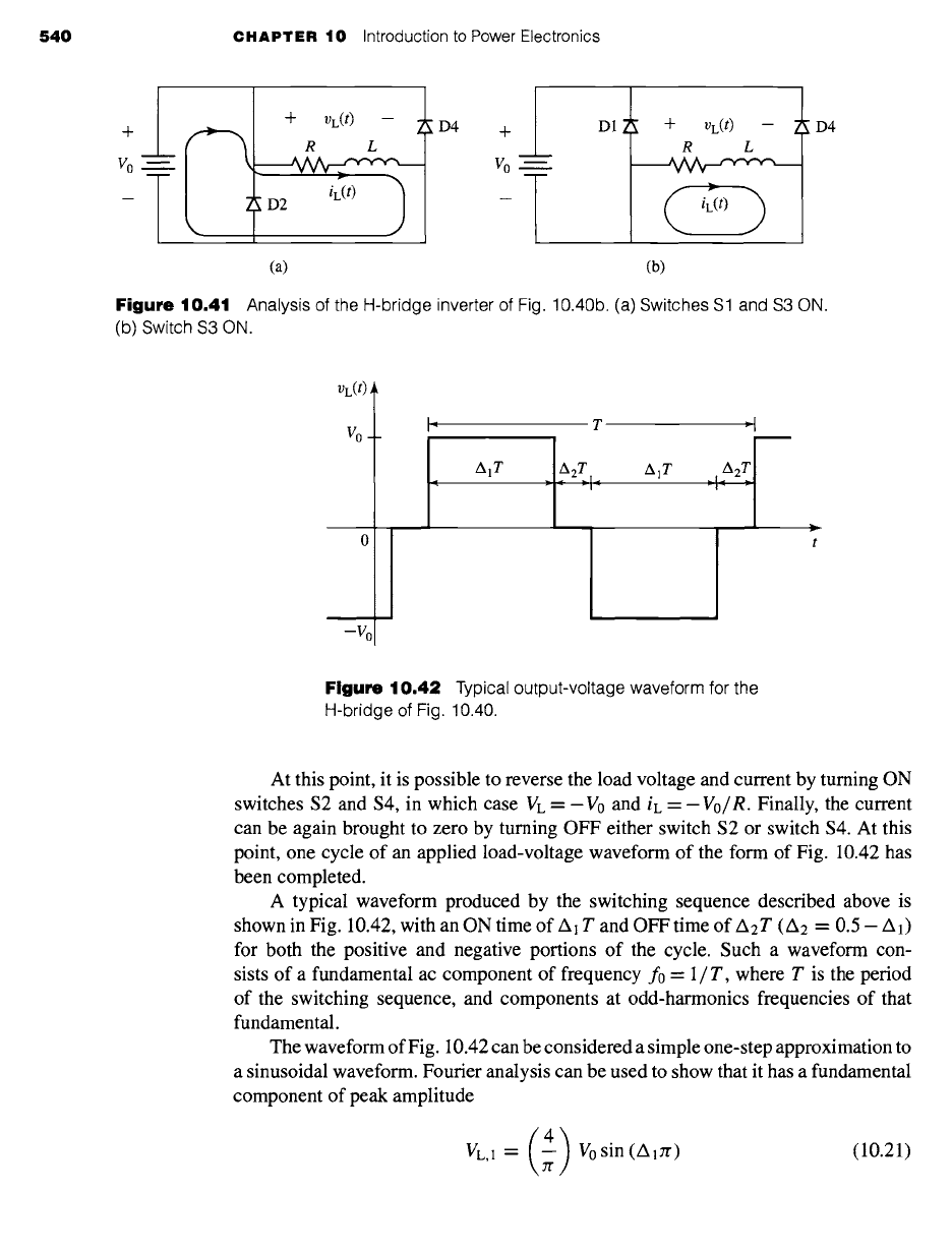
Figure 10.41 Analysis of
the H-bridge inverter
of Fig. 10.40b. (a)
Switches S1 and S3 ON.
(b) Switch S3 ON.
VL(t)
vo
-vo
',~ T -~',
Figure 10.42
Typical output-voltage waveform for the
H-bridge of Fig. 10.40.
At this point, it is possible to reverse the load voltage and current by turning ON
switches $2 and $4, in which case VL =- V0 and iL =-
Vo/R.
Finally, the current
can be again brought to zero by turning OFF either switch $2 or switch $4. At this
point, one cycle of an applied load-voltage waveform of the form of Fig. 10.42 has
been completed.
A typical waveform produced by the switching sequence described above is
shown in Fig. 10.42, with an ON time of Al T and OFF time of A2T (A 2 = 0.5 -- A1)
for both the positive and negative portions of the cycle. Such a waveform con-
sists of a fundamental ac component of frequency f0 = 1/T, where T is the period
of the switching sequence, and components at odd-harmonics frequencies of that
fundamental.
The waveform of Fig. 10.42 can be considered a simple one-step approximation to
a sinusoidal waveform. Fourier analysis can be used to show that it has a fundamental
component of peak amplitude
VL,1 = (4) V0 sin (A,zr) (10.21)
10.3 Inversion: Conversion of DC to AC
541
and n'th-harmonic components (n = 3, 5, 7 .... ) of peak amplitude
(4)
VL,n = ~ V0 sin (n A1Jr) (10.22)
Although this stepped waveform appears to be a rather crude approximation to
a sinusoid, it clearly contains a significant fundamental component. In many appli-
cations it is perfectly adequate as the output voltage of a motor-drive. For example,
three-such waveforms, separated by 120 ° in time phase, could be used to drive a three-
phase motor. The fundamental components would combine to produce a rotating flux
wave as discussed in Chapter 4. In some motor-drive systems, LC filters, consisting
of shunt capacitors operating in conjunction with the motor phase inductances, are
used to reduce the harmonic voltages applied to the motor phase windings.
In general, the higher-order harmonics, whose amplitudes vary inversely with
their harmonic number, as seen from Eq. 10.22, will produce additional core loss in
the stator as well as dissipation in the rotor. Provided that these additional losses are
acceptable both from the point of view of motor heating as well as motor efficiency, a
drive based upon this switching scheme will be quite adequate for many applications.
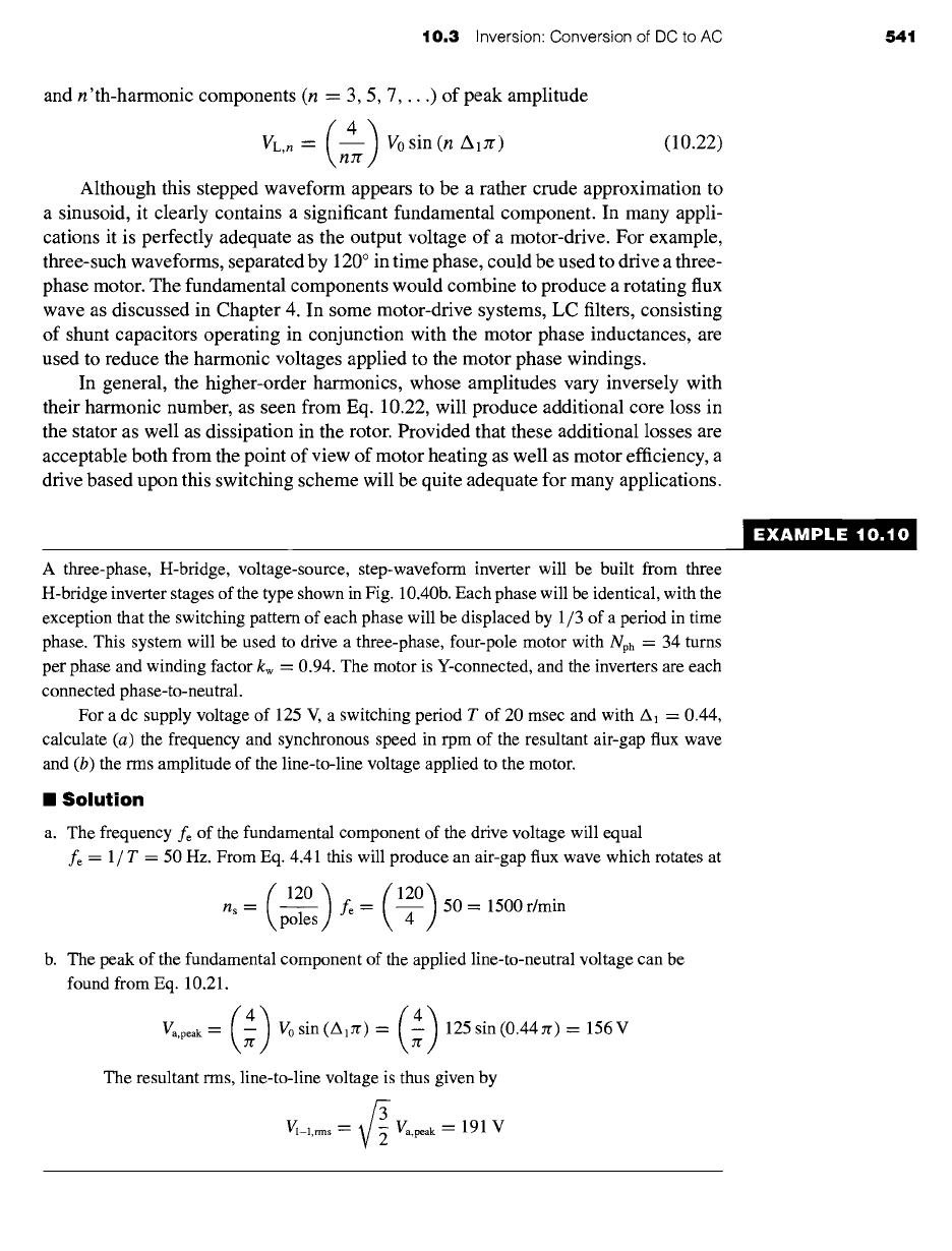
A three-phase, H-bridge, voltage-source, step-waveform inverter will be built from three
H-bridge inverter stages of the type shown in Fig. 10.40b. Each phase will be identical, with the
exception that the switching pattern of each phase will be displaced by 1/3 of a period in time
phase. This system will be used to drive a three-phase, four-pole motor with Nph = 34 turns
per phase and winding factor kw = 0.94. The motor is Y-connected, and the inverters are each
connected phase-to-neutral.
For a dc supply voltage of 125 V, a switching period T of 20 msec and with A1 = 0.44,
calculate (a) the frequency and synchronous speed in rpm of the resultant air-gap flux wave
and (b) the rms amplitude of the line-to-line voltage applied to the motor.
II Solution
a. The frequency fe of the fundamental component of the drive voltage will equal
fe = 1 / T = 50 Hz. From Eq. 4.41 this will produce an air-gap flux wave which rotates at
ns= ~j fe= ~ 50=1500r/min
b. The peak of the fundamental component of the applied line-to-neutral voltage can be
found from Eq. 10.21.
(4) (4)
Va.peak = -- V0 sin (AiJr) = 125 sin (0.44zr) = 156 V
7["
The resultant rms, line-to-line voltage is thus given by
Vl_l,rm s = ~ Va,peak --" 191 V
EXAMPLE 10.10
542 CHAPTER 10 Introduction to Power Electronics
,0t()
/S? ~D1
+ VL(t) _ //S~ ~D4
R L
iL(t)
iL(t)
ol
-/o
(a) (b)
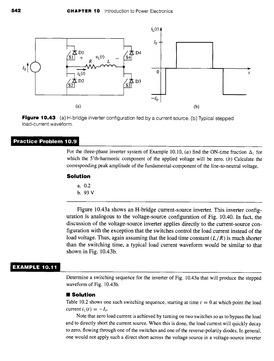
Figure 10.43 (a)
H-bridge inverter configuration fed by a current source. (b) Typical stepped
load-current waveform.
)ractice Problem 10.!
For the three-phase inverter system of Example 10.10, (a) find the ON-time fraction A1 for
which the 5'th-harmonic component of the applied voltage will be zero. (b) Calculate the
corresponding peak amplitude of the fundamental-component of the line-to-neutral voltage.
Solution
a.
0.2
b. 93V
Figure 10.43a shows an H-bridge current-source inverter. This inverter config-
uration is analogous to the voltage-source configuration of Fig. 10.40. In fact, the
discussion of the voltage-source inverter applies directly to the current-source con-
figuration with the exception that the switches control the load current instead of the
load voltage. Thus, again assuming that the load time constant
(L/R)
is much shorter
than the switching time, a typical load current waveform would be similar to that
shown in Fig. 10.43b.
[XAMPLE 10.1"
Determine a switching sequence for the inverter of Fig. 10.43a that will produce the stepped
waveform of Fig. 10.43b.
II Solution
Table 10.2 shows one such switching sequence, starting at time t -- 0 at which point the load
current iL (t) = -- I0.
Note that zero load current is achieved by turning on two switches so as to bypass the load
and to directly short the current source. When this is done, the load current will quickly decay
to zero, flowing through one of the switches and one of the reverse-polarity diodes. In general,
one would not apply such a direct short across the voltage source in a voltage-source inverter
10.3 Inversion: Conversion of DC to AC 543
Table
10.2 Switching sequence used to produce
the load current waveform of Fig. 10.43b.
11.i,1 ,,, ,11...1,,==1,.,
ic(t) S1 $2 $3 S4
-Io OFF ON OFF ON
0 ON ON OFF OFF
Io ON OFF ON OFF
0 OFF OFF ON ON
-1o OFF ON OFF ON
because the resultant current would most likely greatly exceed the ratings of the switches.
However, in the case of a current-source inverter, the switch current cannot exceed that of the
current source, and hence the direct short can be (and, in fact, must be) maintained for as long
as it is desired to maintain zero load current.
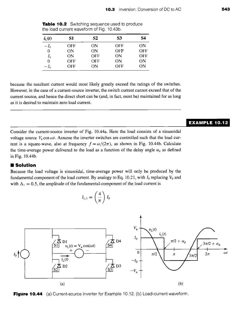
Consider the current-source inverter of Fig. 10.44a. Here the load consists of a sinusoidal
voltage source Va cos cot. Assume the inverter switches are controlled such that the load cur-
rent is a square-wave, also at frequency f =co/(27r), as shown in Fig. 10.44b. Calculate
the time-average power delivered to the load as a function of the delay angle otd as defined
in Fig. 10.44b.
II Solution
Because the load voltage is sinusoidal, time-average power will only be produced by the
fundamental component of the load current. By analogy to Eq. 10.21, with I0 replacing V0 and
with A1 = 0.5, the amplitude of the fundamental-component of the load current is
(4)
L,l=
-
Io
EXAMPLE 10.1,"
,0t(
)
G
1~ D1
4~ D4 /°
Vc(t ) --" V a cos(a~t)
>+O--
0
~2~ iL(t)D2 ~3~ D3 --Va---l°-
(a)
~vL(t)
/__
\ i./=,=+o, /
/ +
o~ d
I I
(b)
Figure
10.44 (a) Current-source inverter for Example 10.12. (b) Load-current waveform.
r
rot
544 CHAPTER
10 Introduction to Power Electronics
and therefore the fundamental component of the load current is equal to
(4)
iL, 1
(t)
=
IL, 1 COS (o.)t
--
O/d)
= --
I 0 COS
(o)t
-
C~d)
7[
The complex amplitude of the load voltage is thus given by f'L = Va and that of the load
current is ]L =
IL, le--Jad.
Thus the time average power is equal to
P =Re[IL " *
= Vi~]= -- VaI0CoSC~d
7l"
By varying the firing-delay angle ad, the power transferred from the source to the load
can be varied. In fact, as C~d is varied over the range 0 < ad < Jr, the power will vary over the
range
()
2 Va/0 > P > Val0
7r 7l"
Note that this inverter can regenerate; i.e., for :r/2 < aa < :r, P < 0 and hence power will
flow from the load back into the inverter.
)ractice Problem 10.1q
The inverter of Example 10.12 is operated with a fixed delay angle C~d = 0 but with a variable
ON-time fraction A~. Find an expression for the time-average power delivered to the load as a
function of A~.
Solution
P=(2) Valosin(A~rr)
10.3.2
Pulse-Width-Modulated Voltage-Source
Inverters
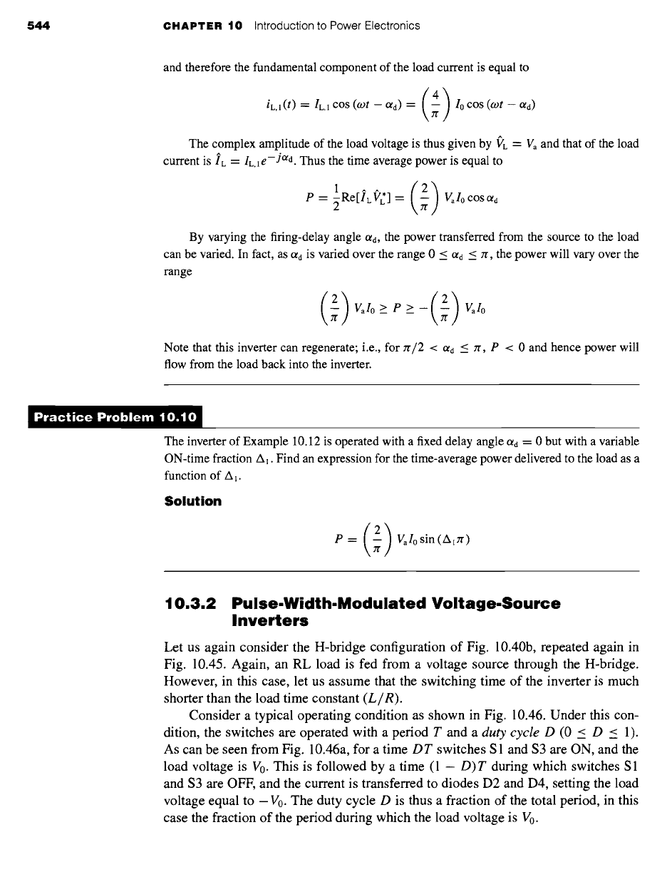
Let us again consider the H-bridge configuration of Fig. 10.40b, repeated again in
Fig. 10.45. Again, an RL load is fed from a voltage source through the H-bridge.
However, in this case, let us assume that the switching time of the inverter is much
shorter than the load time constant (L/R).
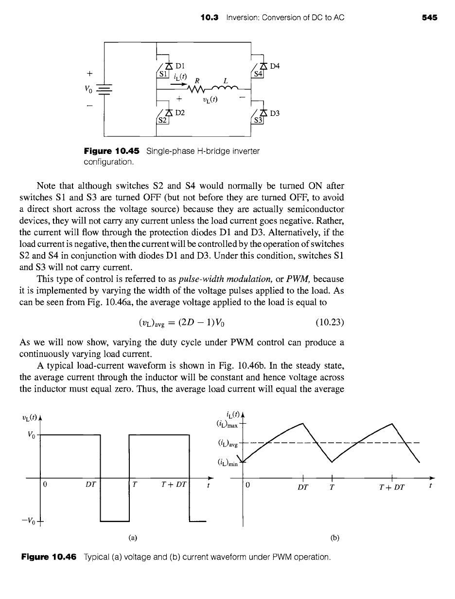
Consider a typical operating condition as shown in Fig. 10.46. Under this con-
dition, the switches are operated with a period T and a
duty cycle D (0 < D < 1).
As can be seen from Fig. 10.46a, for a time
DT
switches S1 and $3 are ON, and the
load voltage is V0. This is followed by a time (1 - D)T during which switches S 1
and $3 are OFF, and the current is transferred to diodes D2 and D4, setting the load
voltage equal to -V0. The duty cycle D is thus a fraction of the total period, in this
case the fraction of the period during which the load voltage is V0.
10.3 Inversion: Conversion of DC to AC 545
4-
Vo m
2~D4
Figure 10.45 Single-phase H-bridge inverter
configuration.
Note that although switches $2 and $4 would normally be turned ON after
switches S1 and $3 are turned OFF (but not before they are turned OFF, to avoid
a direct short across the voltage source) because they are actually semiconductor
devices, they will not carry any current unless the load current goes negative. Rather,
the current will flow through the protection diodes D 1 and D3. Alternatively, if the
load current is negative, then the current will be controlled by the operation of switches
$2 and $4 in conjunction with diodes D 1 and D3. Under this condition, switches S 1
and $3 will not carry current.
This type of control is referred to as pulse-width modulation, or PWM, because
it is implemented by varying the width of the voltage pulses applied to the load. As
can be seen from Fig. 10.46a, the average voltage applied to the load is equal to
(VL)avg ~-~
(2D
-
1) Vo
(10.23)
As we will now show, varying the duty cycle under PWM control can produce a
continuously varying load current.
A typical load-current waveform is shown in Fig. 10.46b. In the steady state,
the average current through the inductor will be constant and hence voltage across
the inductor must equal zero. Thus, the average load current will equal the average
UL(/)
Vo
0
--V 0 _ _
DT
iL(t) ,
(iL)max -
(iL)avg -
(iL)min ~
I I I
0 DT T T + DT
(a)
Figure 10.46 Typical (a) voltage and (b) current waveform under PWM operation.
T T4- DT
(b)