Fitzgerald A.E. Electric Machinery
Подождите немного. Документ загружается.

556 CHAPTER
10 Introduction to Power Electronics
sinusoid, Vs(t) = V0 sinwt. As shown in Fig. 10.31, SCRs T1 and T3 are
triggered together at delay angle Otd (0 < c~d < Jr), and SCRs T2 and T4 are
triggered exactly one-half cycle later.
a. For c~d = n/4:
(i) Sketch the load voltage
v~(t).
(ii) Calculate the average (dc) value Vdc of V's(t).
(iii) Calculate the time-averaged power supplied to the load.
b. Repeat part (a) for otd = 3:r/4.
10.12 A full-wave diode rectifier is fed from a 50-Hz, 220-V rms source whose
series inductance is 12 mH. It drives a load with a resistance 8.4 g2 which
is sufficiently inductive that the load current can be considered to be
essentially dc.
a. Calculate the dc load current Idc and the commutation time tc.
b. Compare the dc current of part (a) with the dc current which would result
if the commutating inductance could be eliminated from the system.
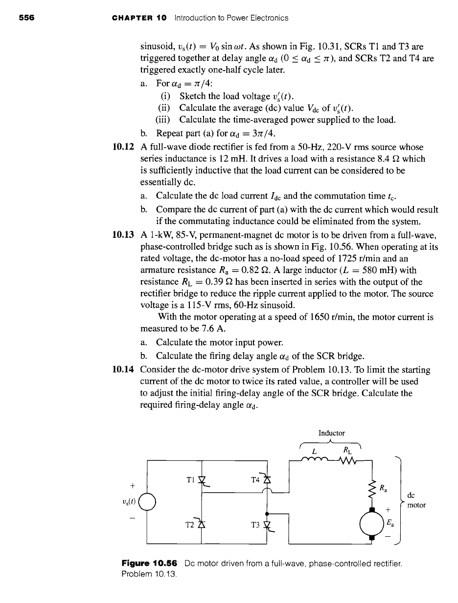
10.13 A 1-kW, 85-V, permanent-magnet dc motor is to be driven from a full-wave,
phase-controlled bridge such as is shown in Fig. 10.56. When operating at its
rated voltage, the dc-motor has a no-load speed of 1725 r/min and an
armature resistance Ra = 0.82 f2. A large inductor (L = 580 mH) with
resistance RL = 0.39 ~2 has been inserted in series with the output of the
rectifier bridge to reduce the ripple current applied to the motor. The source
voltage is a 115-V rms, 60-Hz sinusoid.
With the motor operating at a speed of 1650 r/min, the motor current is
measured to be 7.6 A.
a. Calculate the motor input power.
b. Calculate the firing delay angle
O~ d
of the SCR bridge.
10.14 Consider the dc-motor drive system of Problem 10.13. To limit the starting
current of the dc motor to twice its rated value, a controller will be used
to adjust the initial firing-delay angle of the SCR bridge. Calculate the
required firing-delay angle c~d.
+
v~(t) (
)
T1 ~_
L
T31 _
Inductor
.&
f L RE "~
dc
motor
Figure
10.56 Dc motor driven from a full-wave, phase-controlled rectifier.
Problem 10.13.
10.6 Problems
557
10.15 A three-phase diode bridge is supplied by a three-phase autotransformer
such that the line-to-line input voltage to the bridge can be varied from zero
to 230 V. The output of the bridge is connected to the shunt field winding of
a dc motor. The resistance of this winding is 158 ~. The autotransformer is
adjusted to produce a field current of 1.75 A. Calculate the rms output
voltage of the autotransformer.
10.16 A dc-motor shunt field winding of resistance 210 ~2 is to be supplied from
a 220-V rms, 50-Hz, three-phase source through a three-phase, phase-
controlled rectifier. Calculate the delay angle Otd which will result in a field
current of 1.1 A.
10.17 A superconducting magnet has an inductance of 4.9 H, a resistance of
3.6 m~, and a rated operating current of 80 A. It will be supplied from a
15-V rms, three-phase source through a three-phase, phase-controlled
bridge. It is desired to "charge" the magnet at a constant rate to achieve rated
current in 25 seconds.
a. Calculate the firing-delay angle O~d required to achieve this objective.
b. Calculate the firing-delay angle required to maintain a constant current
of 80 A.
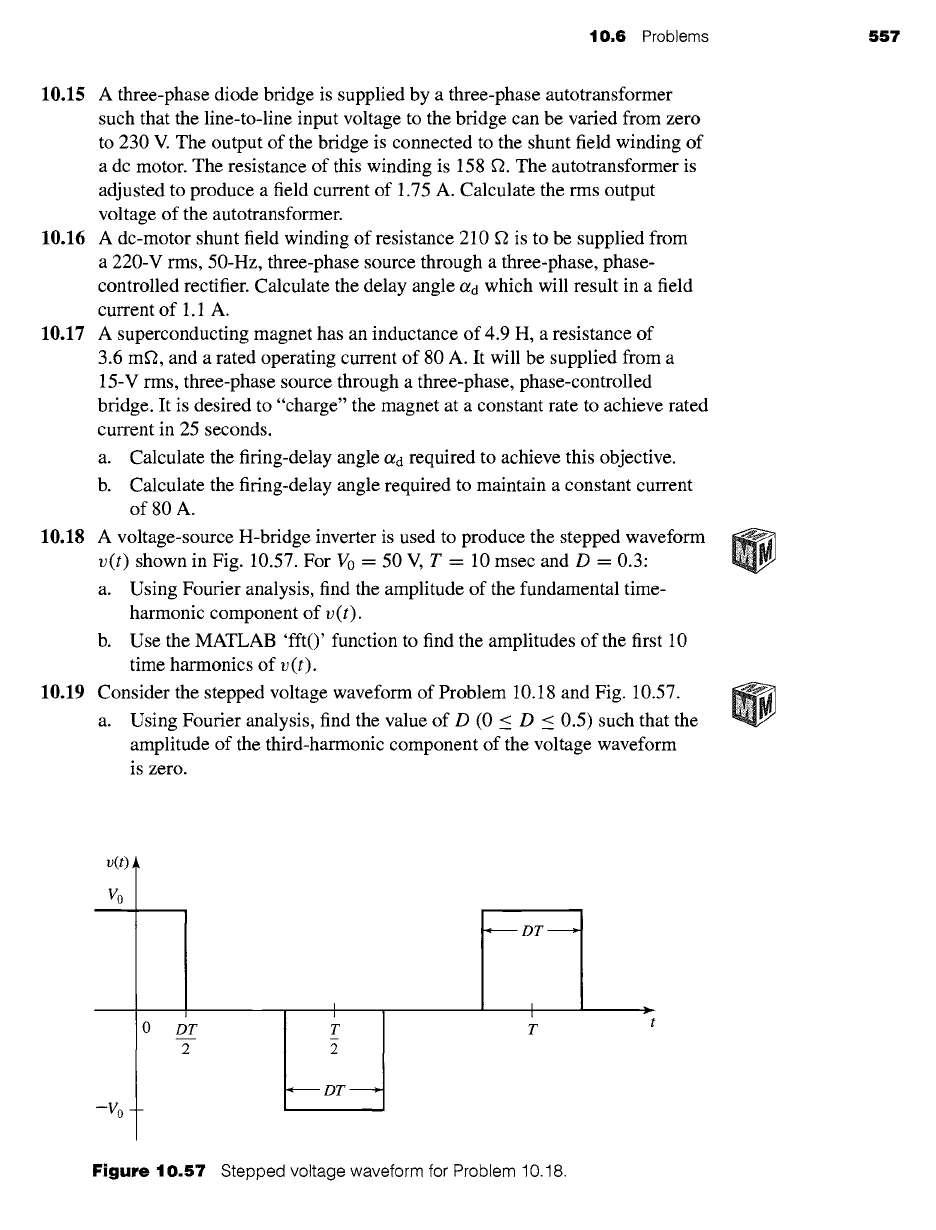
10.18 A voltage-source H-bridge inverter is used to produce the stepped waveform
v(t)
shown in Fig. 10.57. For V0 = 50 V, T = 10 msec and D -- 0.3:
a. Using Fourier analysis, find the amplitude of the fundamental time-
harmonic component of
v(t).
b. Use the MATLAB 'fit()' function to find the amplitudes of the first 10
time harmonics of
v(t).
10.19 Consider the stepped voltage waveform of Problem 10.18 and Fig. 10.57.
a. Using Fourier analysis, find the value of D (0 < D _< 0.5) such that the
amplitude of the third-harmonic component of the voltage waveform
is zero.
v(t)
Vo
-Vo
I I
oo 1:
I
[-" DT ~]
Figure
10.57 Stepped voltage waveform for Problem 10.18.
558 CHAPTER 10 Introduction to Power Electronics
iL(t)
I0
-Io-
I
Old
Old+ D..._.T
2
7t' -+-
Old--~
-~ DT .~
D T 7r Jr- Ol d +
I I I I
:rt" rr+Ol d 2zr 27r+Ol d
D T 27r -t- Old +
7r + Old 2
I- Dr -I
>,
(.ot
DT
2
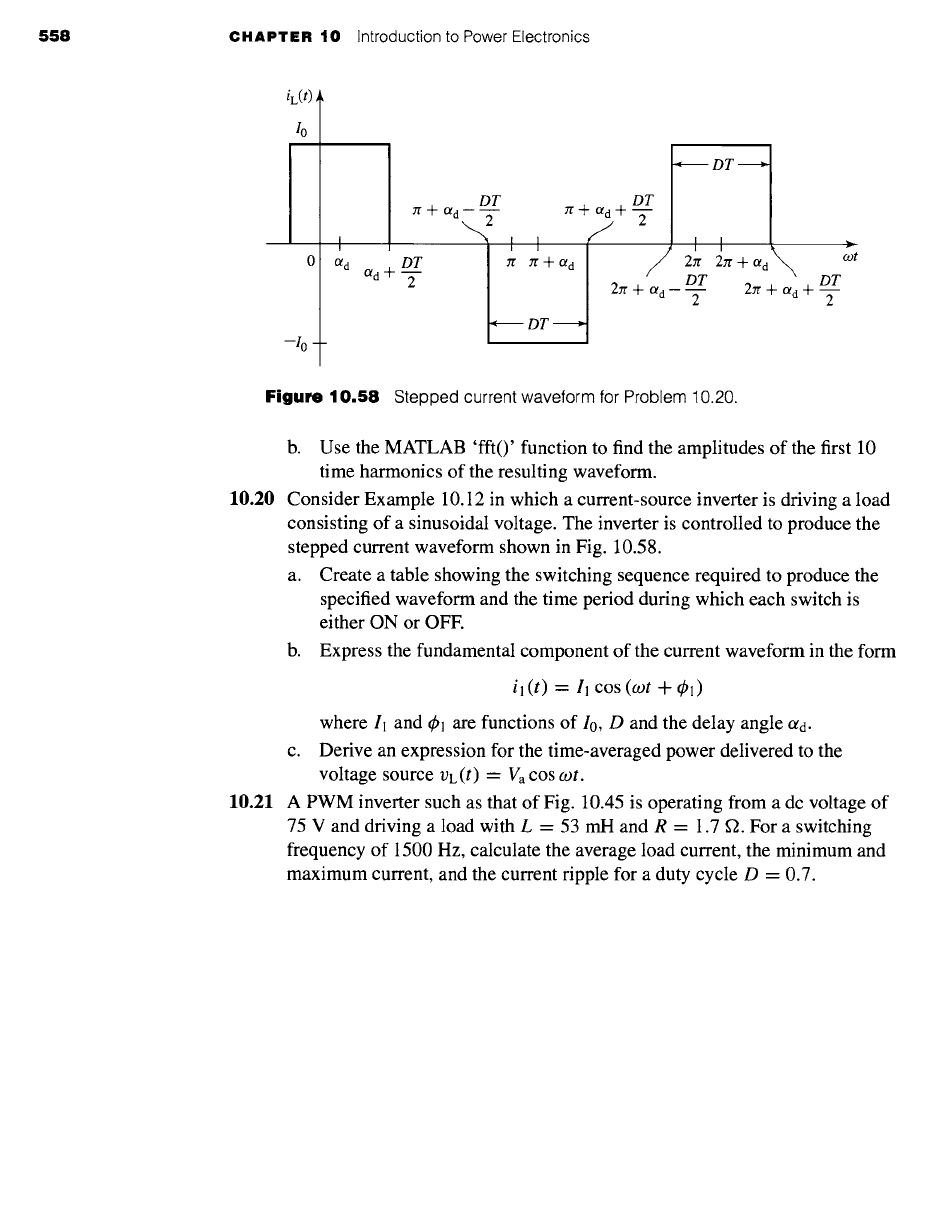
Figure
10.58 Stepped current waveform for Problem 10.20.
b. Use the MATLAB 'fit()' function to find the amplitudes of the first 10
time harmonics of the resulting waveform.
10.20 Consider Example 10.12 in which a current-source inverter is driving a load
consisting of a sinusoidal voltage. The inverter is controlled to produce the
stepped current waveform shown in Fig. 10.58.
a. Create a table showing the switching sequence required to produce the
specified waveform and the time period during which each switch is
either ON or OFF.
b. Express the fundamental component of the current waveform in the form
il(t) = ll
cos (cot +
¢1)
where 11 and
t~l are
functions of I0, D and the delay angle
a d.
c. Derive an expression for the time-averaged power delivered to the
voltage source rE(t) -- Va cos ogt.
10.21 A PWM inverter such as that of Fig. 10.45 is operating from a dc voltage of
75 V and driving a load with L = 53 mH and R = 1.7 f2. For a switching
frequency of 1500 Hz, calculate the average load current, the minimum and
maximum current, and the current ripple for a duty cycle D = 0.7.
CHAPTER
Speed and Torque
Control
y he objective of this chapter is to discuss various techniques for the control of
electric machines. Since an in-depth discussion of this topic is both too exten-
sive for a single chapter and beyond the scope of this book, the presentation
here will necessarily be introductory in nature. We will present basic techniques for
speed and torque control and will illustrate typical configurations of drive electronics
that are used to implement the control algorithms. This chapter will build upon the
discussion of power electronics in Chapter 10.
Note that the discussion of this chapter is limited to steady-state operation. The
steady-state picture presented here is quite adequate for a wide variety of electric-
machine applications. However, the reader is cautioned that system dynamics can play
a critical role in some applications, with concerns ranging from speed of response to
overall system stability. Although the techniques presented here form the basis for
dynamic analyses, the constraints of an introductory textbook are such that a more
extensive discussion, including transient and dynamic behavior, is not possible.
In the discussion of torque control for synchronous and induction machines,
the techniques of field-oriented or vector control are introduced and the analogy is
made with torque control in dc motors. This material is somewhat more sophisticated
mathematically than the speed-control discussion and requires application of the
dq0 transformations developed in Appendix C. The chapter is written such that this
material can be omitted at the discretion of the instructor without detracting from the
discussion of speed control.
11.1 CONTROL OF DC MOTORS
Before the widespread application of power-electronic drives to control ac machines,
dc motors were by far the machines of choice in applications requiring flexibility of
control. Although in recent years ac drives have become quite common, the ease of
control of dc machines insure their continued use in many applications.
559
560 CHAPTER 11 Speed and Torque Control
11.1.1 Speed Control
The three most common speed-control methods for dc motors are adjustment of the
flux, usually by means of field-current control, adjustment of the resistance associated
with the armature circuit, and adjustment of the armature terminal voltage.
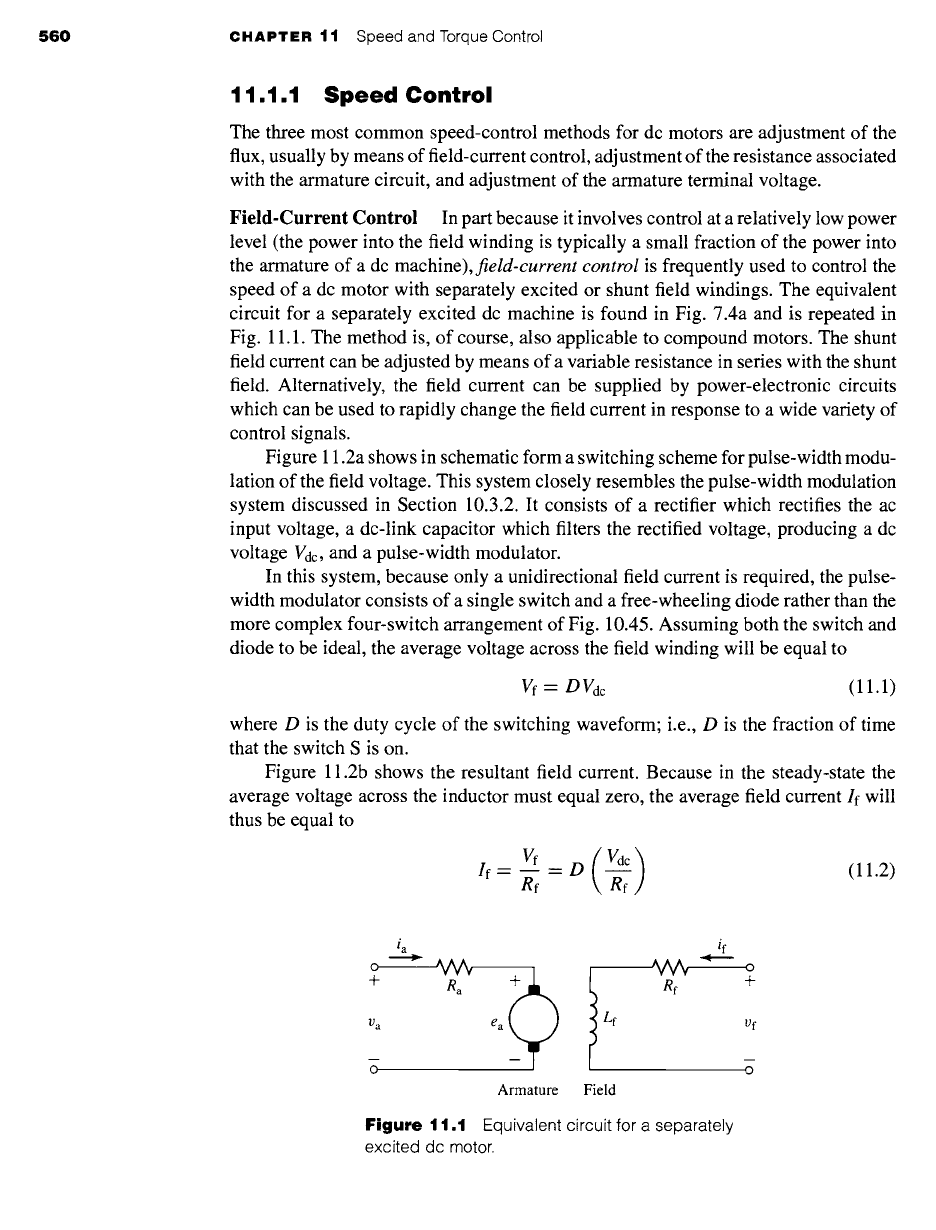
Field-Current Control In part because it involves control at a relatively low power
level (the power into the field winding is typically a small fraction of the power into
the armature of a dc machine),
field-current control
is frequently used to control the
speed of a dc motor with separately excited or shunt field windings. The equivalent
circuit for a separately excited dc machine is found in Fig. 7.4a and is repeated in
Fig. 11.1. The method is, of course, also applicable to compound motors. The shunt
field current can be adjusted by means of a variable resistance in series with the shunt
field. Alternatively, the field current can be supplied by power-electronic circuits
which can be used to rapidly change the field current in response to a wide variety of
control signals.
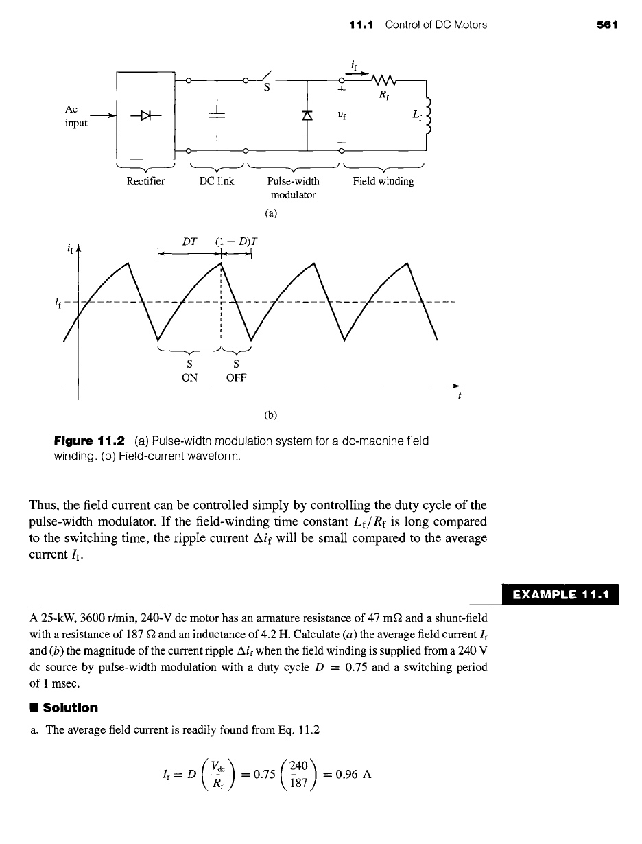
Figure 11.2a shows in schematic form a switching scheme for pulse-width modu-
lation of the field voltage. This system closely resembles the pulse-width modulation
system discussed in Section 10.3.2. It consists of a rectifier which rectifies the ac
input voltage, a dc-link capacitor which filters the rectified voltage, producing a dc
voltage Vdc, and a pulse-width modulator.
In this system, because only a unidirectional field current is required, the pulse-
width modulator consists of a single switch and a free-wheeling diode rather than the
more complex four-switch arrangement of Fig. 10.45. Assuming both the switch and
diode to be ideal, the average voltage across the field winding will be equal to
Vf = DVdc
(11.1)
where D is the duty cycle of the switching waveform; i.e., D is the fraction of time
that the switch S is on.
Figure 11.2b shows the resultant field current. Because in the steady-state the
average voltage across the inductor must equal zero, the average field current If will
thus be equal to
If: Rf -~f (11.2)
i a if
° ~V~ ~ ~ o
+ R a [ Rf +
Va ea I Lf vf
0 0
Armature Field
Figure
11.1 Equivalent circuit for a separately
excited dc motor.
11.1 Control of DC Motors 561
mc
input
if
I i Re
> ~ 1
Vf Lf
I ,
0 0
k.. ~ .yk.~ Jk. J
Rectifier DC link Pulse-width Field winding
modulator
(a)
if*
, DT
(I--D)IT
< >- < >
s s
ON OFF ._
(b)
Figure
11.2 (a) Pulse-width modulation system for a dc-machine field
winding. (b) Field-current waveform.
Thus, the field current can be controlled simply by controlling the duty cycle of the
pulse-width modulator. If the field-winding time constant
Lf/Rf
is long compared
to the switching time, the ripple current Aif will be small compared to the average
current If.
A 25-kW, 3600 r/min, 240-V dc motor has an armature resistance of 47 mf2 and a shunt-field
with a resistance of 187 fZ and an inductance of 4.2 H. Calculate (a) the average field current If
and (b) the magnitude of the current ripple Aif when the field winding is supplied from a 240 V
dc source by pulse-width modulation with a duty cycle D = 0.75 and a switching period
of 1 msec.
II Solution
a. The average field current is readily found from Eq. 11.2
EXAMPLE 11.1
:240)
If-- O k ef = 0.75
\ 1-~
= 0.96 A
562
CHAPTER 11 Speed and Torque Control
b. The field time constant r =
Lf/Rf
= 22.5 msec is much longer that the switching period
of 1 msec. Thus, the ripple current can be calculated using Eq. 10.32 as
(2 dc) O,, O,
Aie= ~ 7
(2x240) ( 1 )
= 187 ~ 0.75x(1-0.75)
= 21.4 mA
~ractice Problem 1 1 .'
The duty-cycle D of the dc-motor controller of Example 11.1 is suddenly switched from 0.75
to 1.0. Calculate (a) the resultant steady-state field current and (b) the time constant for the
change from the initial value of 1.08 A to the new final value.
Solution
a. 1.28 A
b. 22.5 msec
To examine the effect of field-current control, let us begin with the case of a dc
motor driving a load of constant torque Tload. From Eqs. 7.9 and 7.14, the generated
voltage of a dc motor can be written as
Ea -- Kf lfoom ( 11.3)
where If is the average field current,
O) m
is the angular velocity in rad/sec, and Kf =
Ka79dNf is a geometric constant which depends upon the dimensions of the motor,
the properties of the magnetic material used to construct the motor, as well as the
number of turns in the field winding. Note that strictly speaking, Kf is not constant
since it is proportional to the direct-axis permeance, which typically varies as the
flux-level in the motor increases to the point that the effects of magnetic saturation
become significant.
The electromagnetic torque is given by Eq. 7.16 as
Ea Ia
Tmech = =
Kflfla
(11.4)
0.) m
and the armature current can be seen from the equivalent circuit of Fig. 11.1 to be
given by
(Va- Ea)
la = (11.5)
Ra
1 t.1 Control of DC Motors
563
Setting the motor torque equal to
Tload,
Eqs. 11.3 through 11.5 can be solved
for
09 m
Tload Ra
(Va- Iaea) ( Va
gflf )
O)rn = -- (11.6)
Kflf KfIf
From Eq. 11.6, recognizing that the armature resistance voltage drop IaRa is
generally quite small in comparison to the armature voltage Va, we see that for a given
load torque, the motor speed will increase with decreasing field current and decrease
as the field current is increased. The lowest speed obtainable is that corresponding
to maximum field current (the field current is limited by heating considerations); the
highest speed is limited mechanically by the mechanical integrity of the rotor and
electrically by the effects of armature reaction under weak-field conditions giving
rise to poor commutation.
Armature current is typically limited by motor cooling capability. In many dc
motors, cooling is aided by a shaft-driven fan whose cooling capacity is a function
of motor speed. To examine in an approximate fashion the limitations on the allow-
able continuous motor output as the speed is changed, we will neglect the influence
of changing ventilation and assume that the armature current Ia cannot exceed its
rated value, in order to insure that the motor will not overheat. In addition, in our
approximate argument we will neglect the effect of rotational losses (which of course
also change with motor speed). Because the voltage drop across the armature resis-
tance is relatively small, the speed voltage
Ea
will remain essentially constant at a
value slightly below the applied armature voltage; any change in field current will be
compenstated for by a change in motor speed.
Thus under constant-terminal-voltage operation with varying field current, the
Eala product, and hence the allowable motor output power, remain substantially
constant as the speed is varied. A dc motor controlled in this fashion is referred to as
a constant-power drive. Torque, however, varies directly with field flux and therefore
has its highest allowable value at the highest field current and hence lowest speed.
Field-current control is thus best suited to drives requiting increased torque at low
speeds. When a motor so controlled is used with a load requiting constant torque over
the speed range, the rating and size of the machine are determined by the product of
the torque and the highest speed. Such a drive is inherently oversized at the lower
speeds, which is the principal economic factor limiting the practical speed range of
large motors.
am
:~[9_,t ~', ! r,t q :l E i~,'~11
With an armature terminal voltage of 240 V and with a shunt-field current of 0.34 A, the no-load
speed of the dc motor of Example 11.1 is found to be 3600 r/min. In this example, the motor
is assumed to be driving a load which varies with speed as
/°load --
22.4 3-~ kW
where n is the motor speed in r/min. A rheostat is to be installed in series with the shunt field to
vary the speed. Assuming the armature terminal voltage to remain constant at 240 V, calculate
564 CHAPTER
11 Speed and Torque Control
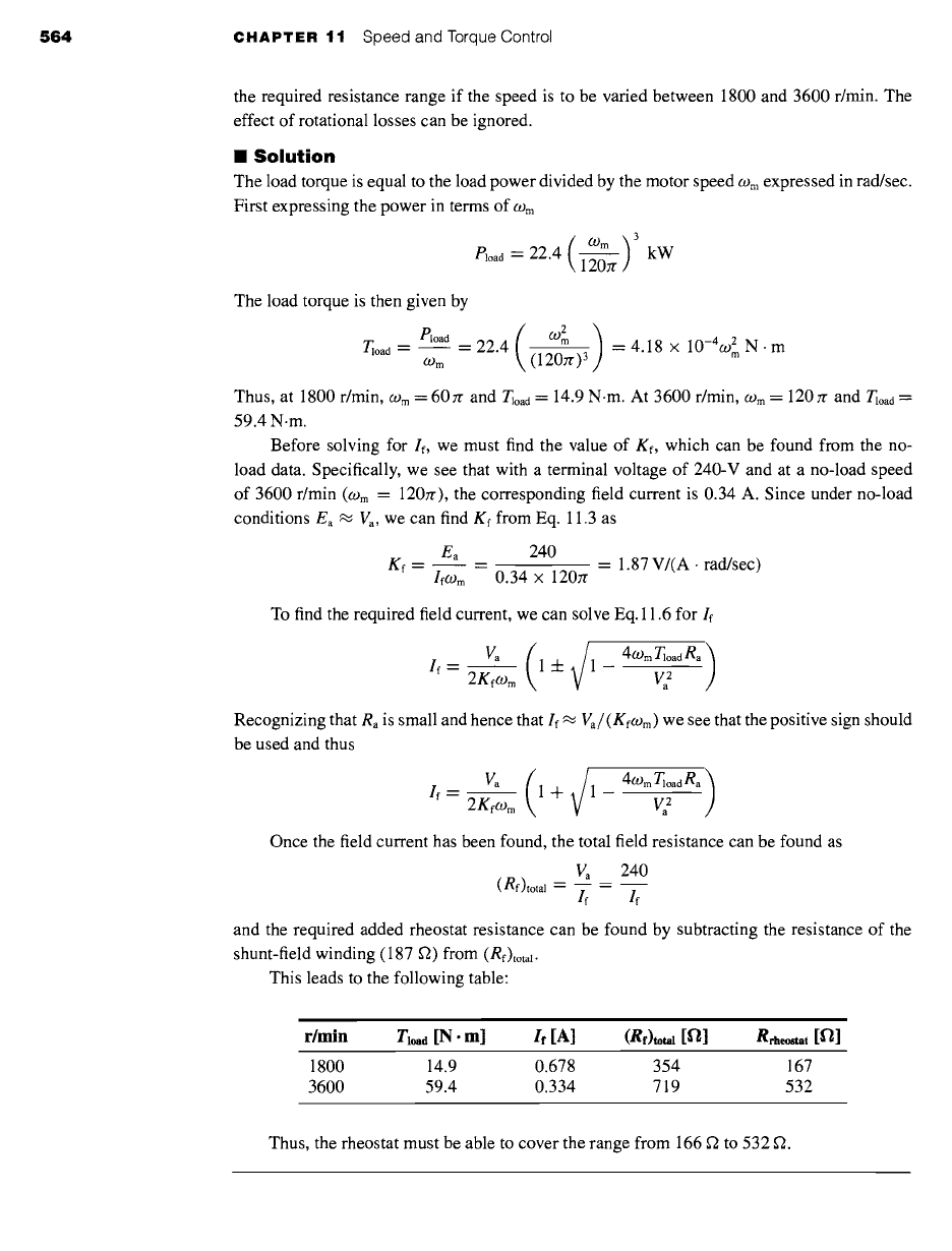
the required resistance range if the speed is to be varied between 1800 and 3600 r/min. The
effect of rotational losses can be ignored.
I
Solution
The load torque is equal to the load power divided by the motor speed
09 m
expressed in rad/sec.
First expressing the power in terms of
09 m
/°load 22.4( Wm ) 3
= kW
120zr
The load torque is then given by
Tloa d
/°load __ 22.4 O)m 4.18 × 1 -4 2
= -- : 0 wmN'm
O) m ( 1 207/" )3
Thus, at 1800 r/min,
(.D m
--- 60 7/" and T~oad = 14.9 N.m. At 3600 r/min,
(.O m :
120zr and T~oad =
59.4 N.m.
Before solving for If, we must find the value of Kf, which can be found from the no-
load data. Specifically, we see that with a terminal voltage of 240-V and at a no-load speed
of 3600 r/min (Wm = 120:r), the corresponding field current is 0.34 A. Since under no-load
conditions Ea "~ Va, we can find Kf from Eq. 11.3 as
Ea 240
Kf = = = 1.87 V/(A. rad/sec)
Ifo) m
0.34 × 120:r
To find the required field current, we can solve Eq. 11.6 for If
If= 2Kfcom
Va
(lq-~/1 - 4°gmTl°adRa )Va 2
Recognizing that Ra is small and hence that If -~
Va/(Kfogm)
we see that the positive sign should
be used and thus
Va
(1 .q_ (1 409m TloadRa )
If = 2gfogm Va 2
Once the field current has been found, the total field resistance can be found as
V a
240
(Rf)tota I : ~ :
If If
and the required added rheostat resistance can be found by subtracting the resistance of the
shunt-field winding (187 f2) from (Rf)totaZ.
This leads to the following table:
|
r/min Tio, d [N. m] If [A] (Rf)~,.i [fl] R~h~t [f~]
1800 14.9 0.678 354 167
3600 59.4 0.334 719 532
Thus, the rheostat must be able to cover the range from 166 f2 to 532 f2.
11.1 Control of DC Motors 565
)ractice Problem 1 1
.:
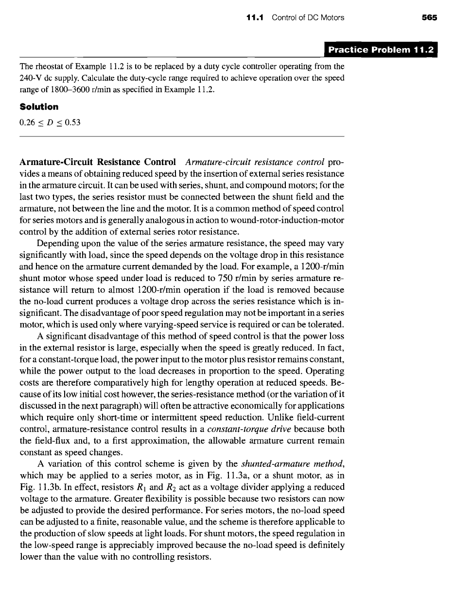
The rheostat of Example 11.2 is to be replaced by a duty cycle controller operating from the
240-V dc supply. Calculate the duty-cycle range required to achieve operation over the speed
range of 1800-3600 r/min as specified in Example 11.2.
Solution
0.26
< D <
0.53
D
Armature-Circuit Resistance Control
Armature-circuit resistance control
pro-
vides a means of obtaining reduced speed by the insertion of external series resistance
in the armature circuit. It can be used with series, shunt, and compound motors; for the
last two types, the series resistor must be connected between the shunt field and the
armature, not between the line and the motor. It is a common method of speed control
for series motors and is generally analogous in action to wound-rotor-induction-motor
control by the addition of external series rotor resistance.
Depending upon the value of the series armature resistance, the speed may vary
significantly with load, since the speed depends on the voltage drop in this resistance
and hence on the armature current demanded by the load. For example, a 1200-r/min
shunt motor whose speed under load is reduced to 750 r/min by series armature re-
sistance will return to almost 1200-r/min operation if the load is removed because
the no-load current produces a voltage drop across the series resistance which is in-
significant. The disadvantage of poor speed regulation may not be important in a series
motor, which is used only where varying-speed service is required or can be tolerated.
A significant disadvantage of this method of speed control is that the power loss
in the external resistor is large, especially when the speed is greatly reduced. In fact,
for a constant-torque load, the power input to the motor plus resistor remains constant,
while the power output to the load decreases in proportion to the speed. Operating
costs are therefore comparatively high for lengthy operation at reduced speeds. Be-
cause of its low initial cost however, the series-resistance method (or the variation of it
discussed in the next paragraph) will often be attractive economically for applications
which require only short-time or intermittent speed reduction. Unlike field-current
control, armature-resistance control results in a
constant-torque drive
because both
the field-flux and, to a first approximation, the allowable armature current remain
constant as speed changes.
A variation of this control scheme is given by the
shunted-armature method,
which may be applied to a series motor, as in Fig. 11.3a, or a shunt motor, as in
Fig. 11.3b. In effect, resistors R1 and R2 act as a voltage divider applying a reduced
voltage to the armature. Greater flexibility is possible because two resistors can now
be adjusted to provide the desired performance. For series motors, the no-load speed
can be adjusted to a finite, reasonable value, and the scheme is therefore applicable to
the production of slow speeds at light loads. For shunt motors, the speed regulation in
the low-speed range is appreciably improved because the no-load speed is definitely
lower than the value with no controlling resistors.