Fitzgerald A.E. Electric Machinery
Подождите немного. Документ загружается.

<o,11
0 ---h II
~mm
a~5 5
~ .
09. W
E ~
< -, <~
o__~
• =r3
~ 0
~ 23" ,-4.
~-~=r
~-o
~ zr
,--,- ~
---t m
~6
~ o
~S
~j- O.
r-'C~
0
..-~.
t~
I
I
I
0
+
I
I
(3"
+
+
+
+
I r
10.2
Rectification: Conversion of AC to DC
527
from which the firing-delay angle corresponding to a given value of dc voltage can
be seen to be
O~d ~ COS-1 (Tg Vdc /
2V0 (10.14)
From Eq. 10.13 we see that the dc voltage applied to the load can vary from 2 V0/zr
to
-2Vo/rc.
This is a rather surprising result in that it is hard to understand how a
rectifier bridge can supply negative voltage. However, in this case, it is necessary to
recognize that this result applies to an inductive load which maintains positive current
flow through the SCRs in spite of the reversal of polarity of the source voltage. If
the load were purely resistive, the current through the conducting SCRs would go
to zero as the source-voltage reversed polarity, and they would simply turn OFF; no
load current would flow until the next pair of SCRs is turned ON.
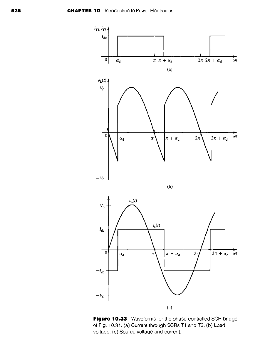
Figure 10.33c shows the source voltage and current waveforms for the phase-
controlled SCR-bridge. We see that the square-wave source current is out of phase
with the source voltage. Its fundamental-harmonic is given by
(4)
is,1 (t) = -- Idc sin (o)t -- Old) (10.15)
7r
and thus the real power supplied to the load is given by
2
P = Vdcldc = -- VoIdc
COSOld
(10.16)
7f
and the reactive power supplied is
2
Q -- -- VoIdc sinotd (10.17)
Under steady-state operation at a load current Iac, Vac - Idc R and the steady-state
rC ldc R
firing-delay angle can be found from Eq. 10.14 to be Ctss - cos-1
(~).
Under this
condition, the real power simply supplies the losses in the resistor and hence P - IEc R.
It may seem strange to be supplying reactive power to a "dc" load. However, careful
analysis will show that this reactive power supplies the energy associated with the
small but finite ripple current through the inductor.
If the delay angle is suddenly reduced (Otd < ass), the dc voltage applied to
the load will increase (see Eq. 10.13) as will the power supplied to the load (see
Eq. 10.16). As a result,
Idc
will begin to increase and the increased power will increase
the energy storage in the inductor. Similarly, if the delay time is suddenly increased
(td > too), Vdc will decrease (it may even go negative) and the power into the load
will decrease, corresponding to a decrease in/de and a decrease in the energy storage
in the inductor.
Note that if Otd > Jr/2, Vdc will be negative, a condition which will continue until
/de reaches zero at which time the SCR bridge will turn OFE Under this condition,
the real power P will also be negative. Under this condition, power is being supplied
from the load to the source and the system is said to be
regenerating.
528 CHAPTER
10 Introduction to Power Electronics
EXAMPLE 10.7
A small superconducting magnet has an inductance L = 1.2 H. Although the resistance of
the magnet itself is essentially zero, the resistance of the external leads is 12.5 m~2. Current
is supplied to the magnet from a 60-Hz, 15-V peak, single-phase source through a phase-
controlled SCR bridge as in Fig. 10.31.
a. The magnet is initially operating in the steady state at a dc current of 35 A. Calculate the
dc voltage applied to the magnet, the power supplied to the magnet, and the delay angle Ota
in msec. Plot the magnet voltage VL (t).
b. In order to quickly discharge the magnet, the delay angle is suddenly increased to ota =
0.9zr = 162 °. Plot the corresponding magnet voltage. Calculate the time required to
discharge the magnet and the maximum power regenerated to the source.
II Solution
The example is most easily solved using MATLAB, which can easily produce the required
plots.
a. Under this steady-state condition, Vdc =
IdcR
= 35 X 0.0125 = 0.438 V. The power
supplied to the magnet is equal to P =
Vdclac
= 0.438 X 35 = 15.3 W, all of which is
going into supplying losses in the lead resistance. The delay angle can be found from
Eq. 10.14.
cos cos
= 1.52 rad = 87.4 °
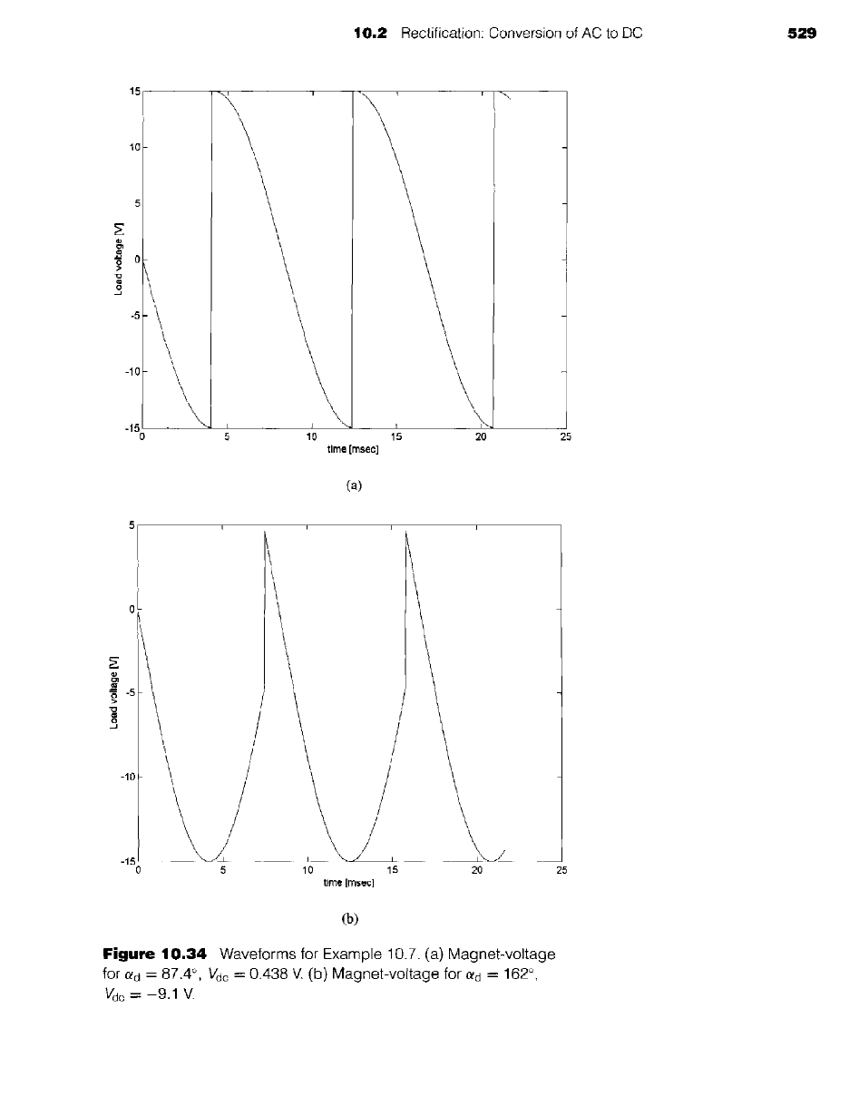
A plot of VL(t) for this condition is given in Fig. 10.34a.
b. For a delay angle of 0.9rr, the dc load voltage will be
= ~ coscq = cos (0.9Jr) = -9.1 V
7/"
A plot of VL(t) for this condition is given in Fig. 10.34b.
The magnet current im can be calculated from the differential equation
dim
Vac -- imR-k- L~
dt
subject to the initial condition that im(0) = 35 A. Thus
im(t) : --R--- + ira(0)- ~ e -(~)r
From this equation we find that the magnet current will reach zero at time t = 4.5
seconds, at which time the bridge will shut off. The power regenerated to the source will
be given by
--Vjcim(t).
It has a maximum value of 9.1 × 35 = 318 W at time t - 0.
II
I
(D
.<
~w
C
q
00 -.~
"-40
-~ o
co
.<~
0
CT -~
~" I-I-I
Ex
~ "o
o o
,--* ---4
~ .
v
~ o
Load voltage [V]
~2
,...,
f
Load voltage [V]
¢j1 (3 ~1 o
...=
¢J.= c)
i i
?f

530 CHAPTER 10 Introduction to Power Electronics
Here is the MATLAB script for Example 10.7.
clc
clear
% system parameters
R = 12.5e-3;
L = 1.2;
V0 = 15;
omega = 120*pi;
% part (a)
% dc current
Idc = 35;
% dc voltage
Vdc_a = R*Idc;
% Power
P = Vdc_a*Idc;
%Calculate the delay angle
alpha_da = acos(pi*R*Idc/(2*V0)) ;
%Now calculate the load voltage
for n = 1:1300
theta(n) = 2*pi*(n-1)/1000;
t(n) = theta (n) /omega;
vs(n) = V0*sin(theta(n)) ;
if theta(n) < alpha_da
vL(n) = -vs(n);
elseif (theta(n) < pi + alpha_da)
vL(n) = vs(n);
elseif theta(n) < 2*pi + alpha_da
vL(n) = -vs(n) ;
elseif theta(n) < 3*pi + alpha_da
vL(n) = vs(n);
elseif theta(n) < 4*pi + alpha_da
vL(n) : -vs(n) ;
else
vL(n) = vs(n);
end
end
plot(1000*t,vL)
xlabel('time [msec] ')
ylabel('Load voltage [V] ')
pause
% part (b)

10.2 Rectification: Conversion of AC to DC 531
% delay angle
alpha_db = 0.9*pi;
% Find the new dc voltage
Vdc_b = (2*V0/pi)*cos(alpha_db);
% Time constants
tau = L/R;
% Initial current
im0 = Idc ;
% Calculate the time at which the current reaches zero
tzero = -tau*log((-Vdc_b/R)/(im0-Vdc_b/R)) ;
% Now plot the load voltage
for n = 1:1300
theta(n) : 2*pi*(n-1)/1000;
t(n) : theta (n) /omega;
vs(n) = V0*sin(theta(n)) ;
if theta(n) < alpha_db
vL(n) = -vs(n);
elseif (theta(n) < pi + alpha_db)
vL(n) = vs(n);
elseif theta(n) < 2*pi + alpha_db
vL(n) = -vs(n);
elseif theta(n) < 3*pi + alpha_db
vL(n) = vs(n);
elseif theta(n) < 4*pi + alpha_db
vL(n) = -vs(n);
else
vL(n) = vs(n);
end
end
plot (1000*t, vL)
xlabel('time [msec] ')
ylabel('Load voltage [V] ')
fprintf('part (a) :')
fprintf('\n Vdc_a = %g [mV] ',1000*Vdc_a)
fprintf('\n Power = %g [W] ',P) ;
fprintf('\n alpha_d=%g [tad] =%g [degrees] ',alpha_da,180*alpha_da/pi)
fprintf('\npart (b) :')
fprintf('\n alpha_d=%g [rad] =%g [degrees] ',alpha_db,180*alpha_db/pi)
fprintf('\n Vdc_b = %g [V] ',Vdc_b)
fprintf('\n Current will reach zero at %g [sec] ',tzero)
fprintf('\n')
532 CHAPTER 10 Introduction to Power Electronics
The field winding of a small synchronous generator has a resistance of 0.3 f2 and an inductance
of 250 mH. It is fed from a 24-V peak, single-phase 60-Hz source through a full-wave phase-
controlled SCR bridge. (a) Calculate the dc voltage required to achieve a dc current of 18 A
through the field winding and the corresponding firing-delay angle. (b) Calculate the field
current corresponding to a delay angle of 45 °.
Solution
a. 5.4 V, 69 °
b. 36.0 A
10.2.5 Inductive Load with a Series DC Source
As we have seen in Chapter 9, dc motors can be modeled as dc voltage sources in
series with an inductor and a resistor. Thus, it would be useful to briefly investigate
the case of a dc voltage source in series with an inductive load.
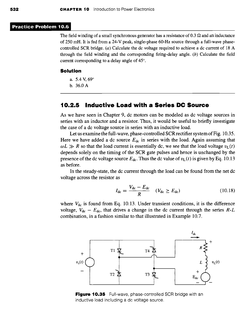
Let us examine the full-wave, phase-controlled SCR rectifier system of Fig. 10.35.
Here we have added a dc source Edc in series with the load. Again assuming that
coL >> R so that the load current is essentially dc, we see that the load voltage VL(t)
depends solely on the timing of the SCR gate pulses and hence is unchanged by the
presence of the dc voltage source Edc. Thus the dc value of VL(t) is given by Eq. 10.13
as before.
In the steady-state, the dc current through the load can be found from the net dc
voltage across the resistor as
Vdc-
Edc
Idc-- (Vale >_ Edc) (10.18)
R
where Vac is found from Eq. 10.13. Under transient conditions, it is the difference
voltage, Vac - Eac, that drives a change in the dc current through the series
R-L
combination, in a fashion similar to that illustrated in Example 10.7.
+
Vs(t)
m
T1 ~L
T2
T4"~
f
T3
dc
R +
4- VL(t)
Figure 10.35
Full-wave, phase-controlled SCR bridge with an
inductive load including a dc voltage source.

10.2 Rectification: Conversion of AC to DC
533
A small permanent-magnet dc motor is to be operated from a phase-controlled bridge. The
60-Hz ac waveform has an rms voltage of 35 volts. The dc motor has an armature resistance
of 3.5 f2 and an armature inductance of 17.5 mH. It achieves a no-load speed of 8000 r/min at
an armature voltage of 50 V.
Calculate the no-load speed in r/min of the motor as a function of the firing delay angle Otd.
II
Solution
In Section 7.7 we see that the equivalent circuit for a permanent-magnet dc motor consists of
a dc source (proportional to motor speed) in series with an inductance and a resistance. Thus,
the equivalent circuit of Fig. 10.35 applies directly to the situation of this problem.
From Eq. 7.26, the generated voltage from the dc motor (Edc in Fig. 10.35) is proportional
to the speed of the dc motor. Thus,
(8oo0)
n= -~ Edc=160Edcr/min
Under steady state operation, the dc voltage drop across the armature inductance will be
zero. In addition, at no load, the armature current will be sufficiently small that the voltage
drop across the armature resistance can be neglected. Thus, setting Edc = Vdc and substituting
the expression for Vdc from Eq. 10.13 give,
= =
= cos ota = 31.5 cos ota
Jr
Note that because the bridge can only supply positive current to the dc motor (and hence, in the
steady-state, the dc voltage must be positive), this expression is valid only for 0 _< otd < ~r/2.
Finally, substituting the expression for the speed n in terms of Eac gives
n = 160 x (31.5 cosotd) = 5040 cosota r/rain (0 < otd < zr/2)
)ractice Problem 10.
The dc-motor of Example 10.8 is observed to be operating at a speed of 3530 r/min and drawing
a dc current of 1.75 ampere. Calculate the corresponding firing delay angle Otd.
Solution
ota = 0.15zr rad = 27 °
10.2.6 Three-Phase Bridges
Although many systems with ratings ranging up to five or more kilowatts run off
single-phase power, most large systems are supplied from three-phase sources. In
general, all of the issues which we have discussed with regard to single-phase,
Va(t)
Vb(t)
Vc(t)
(a)
R OR(t)
D4 D5 ~ D6 ~ -
X/'2 V l-l, rms
OR(t)
[
-~- VH, rms
534 CHAPTER 10 Introduction to Power Electronics
(b)
(.or
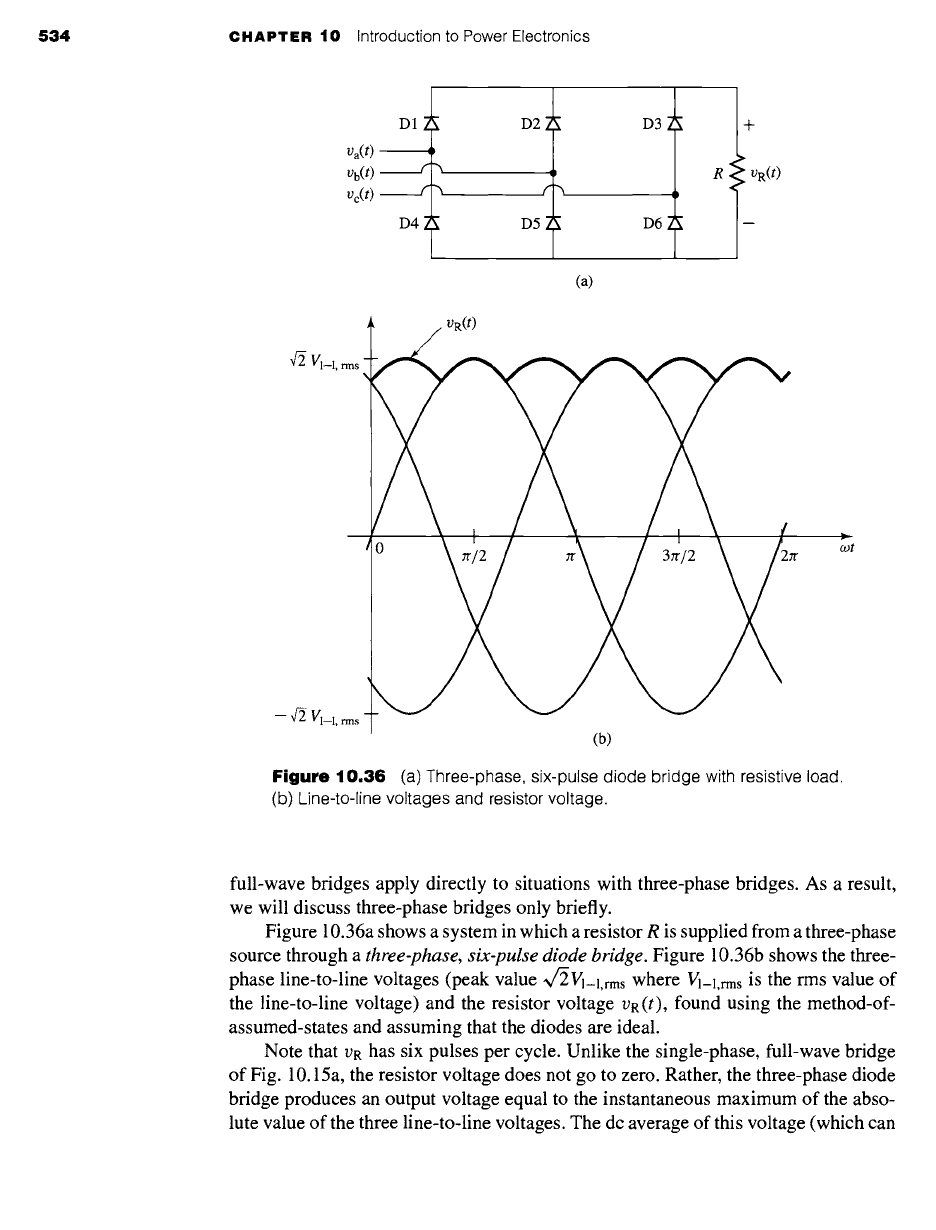
Figure 10.36 (a)
Three-phase, six-pulse diode bridge with resistive load.
(b) Line-to-line voltages and resistor voltage.
full-wave bridges apply directly to situations with three-phase bridges. As a result,
we will discuss three-phase bridges only briefly.
Figure 10.36a shows a system in which a resistor R is supplied from a three-phase
source through a
three-phase, six-pulse diode bridge.
Figure 10.36b shows the three-
phase line-to-line voltages (peak value ~/2Vl-i,rms where Vl-l,rms is the rms value of
the line-to-line voltage) and the resistor voltage VR(t), found using the method-of-
assumed-states and assuming that the diodes are ideal.
Note that VR has six pulses per cycle. Unlike the single-phase, full-wave bridge
of Fig. 10.15a, the resistor voltage does not go to zero. Rather, the three-phase diode
bridge produces an output voltage equal to the instantaneous maximum of the abso-
lute value of the three line-to-line voltages. The dc average of this voltage (which can
10.2
Rectification: Conversion of AC to DC 535
be obtained by integrating over 1/6 of a cycle) is given by
Vdc -- ~
--Vbc(t) dt
7it
3o9 ~
~/~Wl-1 rms
sin
cot dt
zr '
3~/-2) Vl_Lrms (10.19)
where
Vl-l,rms
is the rms value of the line-to-line voltage.
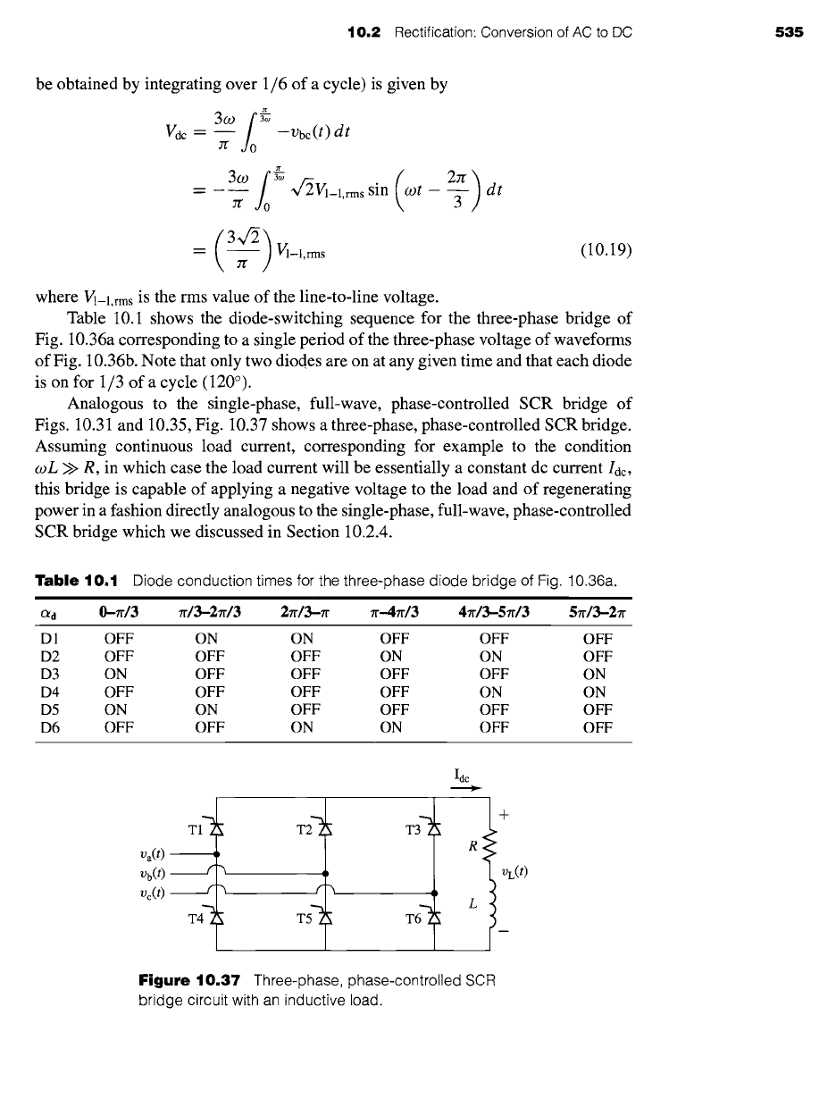
Table 10.1 shows the diode-switching sequence for the three-phase bridge of
Fig. 10.36a corresponding to a single period of the three-phase voltage of waveforms
of Fig. 10.36b. Note that only two diodes are on at any given time and that each diode
is on for 1/3 of a cycle (120°).
Analogous to the single-phase, full-wave, phase-controlled SCR bridge of
Figs. 10.31 and 10.35, Fig. 10.37 shows a three-phase, phase-controlled SCR bridge.
Assuming continuous load current, corresponding for example to the condition
coL >> R, in which case the load current will be essentially a constant dc current loc,
this bridge is capable of applying a negative voltage to the load and of regenerating
power in a fashion directly analogous to the single-phase, full-wave, phase-controlled
SCR bridge which we discussed in Section 10.2.4.
Table
10,1 Diode conduction times for the three-phase diode bridge of Fig. 10.36a.
mmw
lit i
C~d 0-7r/3 ~'/3-2zr/3 2~/3--n" ~'-4~'/3 4~/3-5zr/3 5~/3--2~
D1 OFF ON ON OFF OFF OFF
D2 OFF OFF OFF ON ON OFF
D3 ON OFF OFF OFF OFF ON
D4 OFF OFF OFF OFF ON ON
D5 ON ON OFF OFF OFF OFF
D6 OFF OFF ON ON OFF OFF
Va(t)
Vb(t)
V¢(t)
T T T6
Idc
+
R
VL(t)
L
Figure 10.37
Three-phase, phase-controlled SCR
bridge circuit with an inductive load.