Fitzgerald A.E. Electric Machinery
Подождите немного. Документ загружается.

546 CHAPTER 10 Introduction to Power Electronics
voltage divided by the resistance or
(VL)avg [2D - 1 ] V0
(iL)avg =
R - R (10.24)
Thus we see that by varying the duty cycle D over the range of 0 to 1, we can vary
the load current over the range
-Vo/R <_
(iL)avg _<
Vo/R.
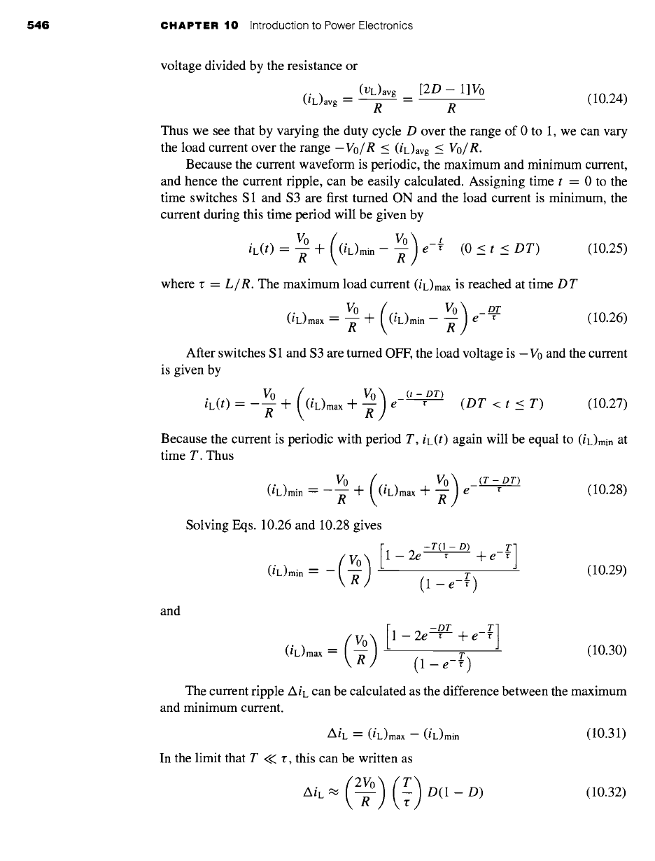
Because the current waveform is periodic, the maximum and minimum current,
and hence the current tipple, can be easily calculated. Assigning time t = 0 to the
time switches S1 and $3 are first turned ON and the load current is minimum, the
current during this time period will be given by
Vo ( Vo ) t DT)
(10.25)
iL(t) -- -~- 4-
(iL)min
R e- (0 < t <
where r =
L/R.
The maximum load current
(iL)max
is reached at time
DT
(iL)max V0 4- ((iL)min
go) DT
= e ~ (10.26)
R R
After switches S 1 and $3 are turned OFF, the load voltage is - V0 and the current
is given by
iL(t) = V° 4- ((iL)max 4-
VO) (t-DT,
R ~ e r (DT <t < T)
(10.27)
Because the current is periodic with period T, iL(t) again will be equal to
(iL)min
at
time T. Thus
and
(iL)min = V0
( Vo ) (T- DT)
R + (iL)max 4-
-~- e- r
(10.28)
Solving Eqs. 10.26 and 10.28 gives
1 2e -T(1 - D) T]
(__~)
- r +e-~
(iL)min = --
(1 - e -T)
(10.29)
-DT ]
(V o)l-2e---v- +e-~ r
(iL)max = -~-
(1 - e -T) (10.30)
The current ripple AiL can be calculated as the difference between the maximum
and minimum current.
AiL -- (iL)max -- (iL)min
In the limit that T << r, this can be written as
AiL ~ -~- r
(10.31)
(10.32)

10.3 Inversion: Conversion of DC to AC
547
-XAMPLE 10.1
A PWM inverter such as that of Fig. 10.45 is operating from a dc voltage of 48 V and driving
a load with L = 320 mH and R = 3.7 g2. For a switching frequency of 1 kHz, calculate the
average load current, the minimum and maximum current, and the current ripple for a duty
cycle D = 0.8.
II Solution
From Eq. 10.24, the average load current will equal
[2D- 1]V0 0.6 x 48
(iL)avg =
R = 3.7 = 7.78 A
For a frequency of 1 kHz, the period T = 1 msec. The time constant r = L/R = 86.5 msec.
(iL)min
and
(iL)max can
then be found from Eqs. 10.29 and 10.30 to be
(iL)min ~---
7.76 A and
(iL)max --"
7.81 A. Thus the current tipple, calculated from Eq. 10.31, is 0.05 A, which is equal
to 0.6 percent of the average load current. Alternatively, using the fact that
T/r
= 0.012 << 1,
the current ripple could have been calculated directly from Eq. 10.32
(2~0) (T) (2×48) (8@.5)
A/L = ~ D(1 - D) = 3.7 x 0.8 x 0.2 = 0.05 A
~ractice Problem 10.1'
Calculate (a) the average current and (b) the current tipple for the PWM inverter of Exam-
ple 10.13 if the switching frequency is reduced to 250 Hz.
Solution
a. 7.78 A (unchanged from Example 10.13)
b. 0.19 A
Now let us consider the situation for which the duty cycle is varied with time,
i.e., D =
D(t).
If
D(t)
varies slowly in comparison to the period T of the switching
frequency, from Eq. 10.23, the average load voltage will be equal to
(VL)avg = [2D(t) - 1]V0 (10.33)
and the average load current will be
[2D(t)- 1]V0
(iL)avg = R (10.34)
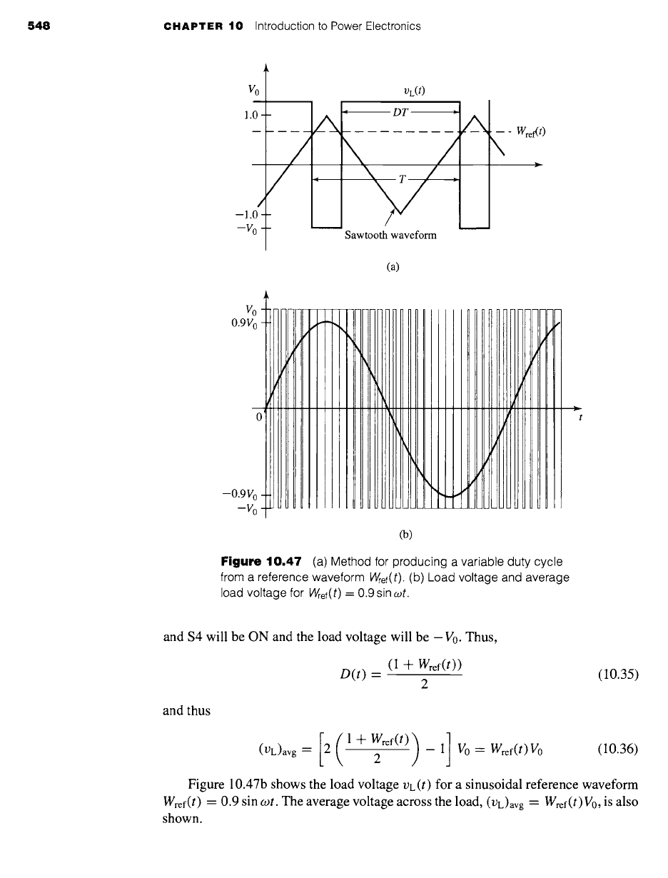
Figure 10.47a illustrates a method for producing the variable duty cycle for this
system. Here we see a saw-tooth waveform which varies between -1 and 1. Also
shown is a reference waveform Wref(t) which is constrained to lie within the range - 1
and 1. The switches will be controlled in pairs. During the time that Wref(t) is greater
than the saw-tooth waveform, switches S1 and $3 will be ON and the load voltage
will be V0. Similarly, when Wref(t) is less than the saw-tooth waveform, switches $2
548 CHAPTER 10 Introduction to Power Electronics
VO
T VL(t)
1.0 -
--JV~ t Sawtooth waveform
(a)
Get{ t )
Vo
0.9V o -
0 ~
--0.9% -
--V 0 -
(b)
Figure
10.47 (a) Method for producing a variable duty cycle
from a reference waveform
Wref(t). (b)
Load voltage and average
load voltage for
Wref(t)
= 0.9 sin cot.
and $4 will be ON and the load voltage will be -Vo. Thus,
(1 -]-- Wref(t))
D(t) --
(10.35)
2
and thus
[ (, + ref"') ,] v0 ref,,,V0
(VL)avg -- 2 2
(10.36)
Figure 10.47b shows the load voltage VL(t) for a sinusoidal reference waveform
Wref(t) --
0.9 sin cot. The average voltage across the load, (VL)avg
-- Wref(t) V0,
is also
shown.
10.3 Inversion: Conversion of DC to AC 549
,otO
VoO] ] 42~ D4
12•D
1 ~$2+ D2 D3
Va(t)
Vb(t)
Vc(t)
~4~D4 5~D5 ~ D6
(a) (b)
D2
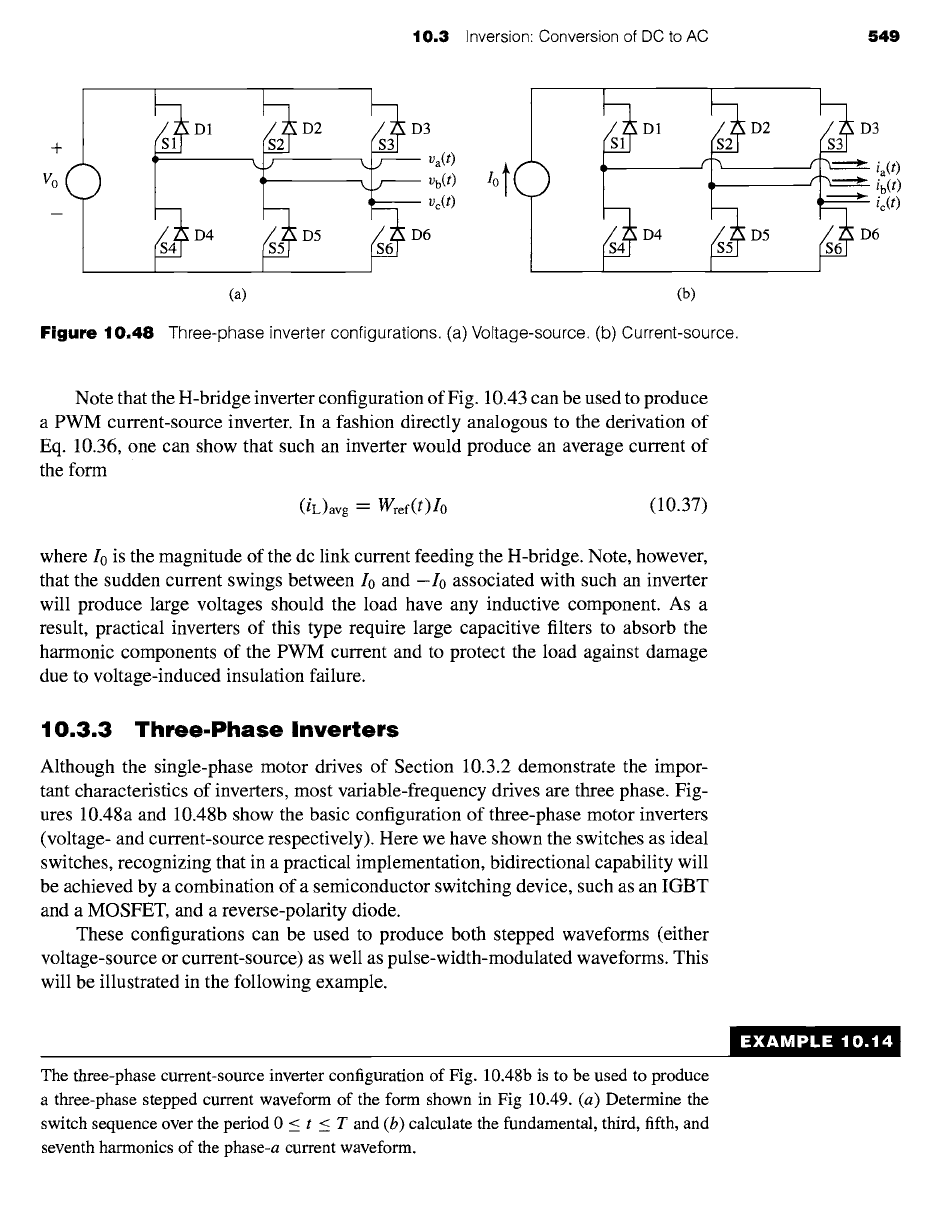
Figure
10.48 Three-phase inverter configurations. (a) Voltage-source. (b) Current-source.
D5
!ii
Note that the H-bridge inverter configuration of Fig. 10.43 can be used to produce
a PWM current-source inverter. In a fashion directly analogous to the derivation of
Eq. 10.36, one can show that such an inverter would produce an average current of
the form
(iL)avg--"
Wref(t)Io
(10.37)
where I0 is the magnitude of the dc link current feeding the H-bridge. Note, however,
that the sudden current swings between I0 and -I0 associated with such an inverter
will produce large voltages should the load have any inductive component. As a
result, practical inverters of this type require large capacitive filters to absorb the
harmonic components of the PWM current and to protect the load against damage
due to voltage-induced insulation failure.
10.3.3 Three.Phase Inverters
Although the single-phase motor drives of Section 10.3.2 demonstrate the impor-
tant characteristics of inverters, most variable-frequency drives are three phase. Fig-
ures 10.48a and 10.48b show the basic configuration of three-phase motor inverters
(voltage- and current-source respectively). Here we have shown the switches as ideal
switches, recognizing that in a practical implementation, bidirectional capability will
be achieved by a combination of a semiconductor switching device, such as an IGBT
and a MOSFET, and a reverse-polarity diode.
These configurations can be used to produce both stepped waveforms (either
voltage-source or current-source) as well as pulse-width-modulated waveforms. This
will be illustrated in the following example.
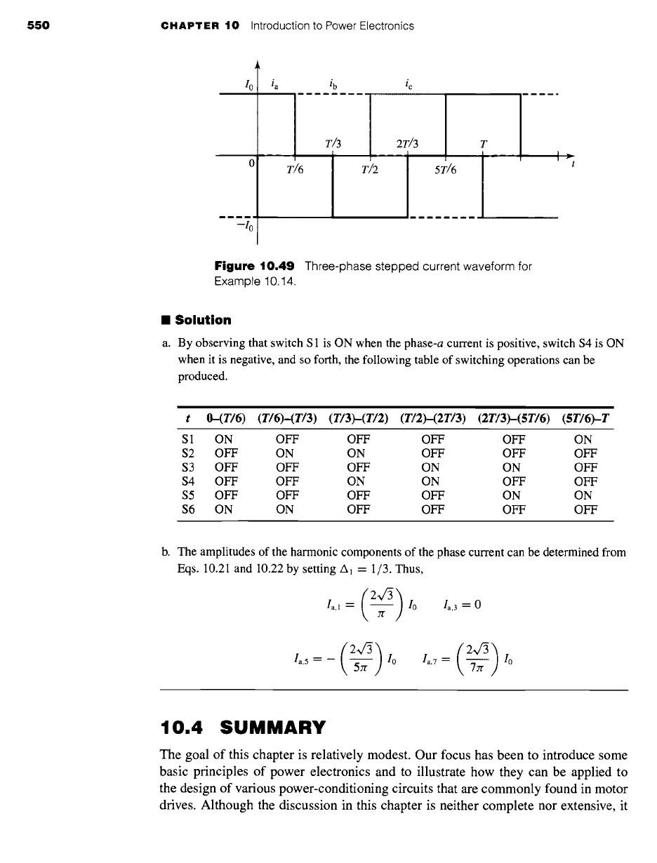
The three-phase current-source inverter configuration of Fig. 10.48b is to be used to produce
a three-phase stepped current waveform of the form shown in Fig 10.49. (a) Determine the
switch sequence over the period 0 < t < T and (b) calculate the fundamental, third, fifth, and
seventh harmonics of the phase-a current waveform.
EXAMPLE 10.14
550 CHAPTER 10 Introduction to Power Electronics
I 0 ia ib ic
m ~ m m ,,, m m u, ......................................
01 T/6 T~2
5T/6 ~t
~mmm ...........
-,o1
Figure 10.49
Three-phase stepped current waveform for
Example 10.14.
II Solution
a. By observing that switch S 1 is ON when the phase-a current is positive, switch $4 is ON
when it is negative, and so forth, the following table of switching operations can be
produced.
t O-(T/6) (T/6)-(T/3) (T/3)-(T/2) (T/2)-(2T/3)
(2T/3)-(5T/6)
(5T/6)-T
S1 ON OFF OFF OFF OFF ON
S2 OFF ON ON OFF OFF OFF
S3 OFF OFF OFF ON ON OFF
$4 OFF OFF ON ON OFF OFF
S5 OFF OFF OFF OFF ON ON
$6 ON ON OFF OFF OFF OFF
b. The amplitudes of the harmonic components of the phase current can be determined from
Eqs. 10.21 and 10.22 by setting A~ = 1/3. Thus,
/a,l = ~ /0 /a,3 = 0
*a,'=-- T~ *0
/5'~
la,7 --
--~ ] Io
10.4 SUMMARY
The goal of this chapter is relatively modest. Our focus has been to introduce some
basic principles of power electronics and to illustrate how they can be applied to
the design of various power-conditioning circuits that are commonly found in motor
drives. Although the discussion in this chapter is neither complete nor extensive, it
10.4 Summary 551
is intended to provide the background required to support the various discussions of
motor control which are presented in this book.
We began with a brief overview of a few of the available solid-state switching
devices: diodes, SCRs, IGBTs and MOSFETs, and so on. We showed that, for the
purposes of a preliminary analysis, it is quite sufficient to represent these devices as
ideal switches. To emphasize the fact that they typically can pass only unidirectional
current, we included ideal diodes in series with these switches. The simplest of these
devices is the diode, which has only two terminals and is turned ON and OFF simply
by the conditions of the external circuit. The remainder have a third terminal which
can be used to turn the device ON and, in the case of transistors such as MOSFETS
and IGBTs, OFF again.
A typical variable-frequency, variable-voltage motor-drive system can be con-
sidered to consist of three sections. The input section rectifies the power-frequency,
fixed-voltage ac input and produces a dc voltage or current. The middle section filters
the rectifier output, producing a relatively constant dc current or voltage, depending
upon the type of drive under consideration. The output inverter section converts the dc
to variable-frequency, variable-voltage ac voltages or currents which can be applied
to the terminals of a motor.
The simplest inverters we investigated produce stepped voltage or current wave-
forms whose amplitude is equal to that of the dc source and whose frequency can
be controlled by the timing of the inverter switches. To produce a variable-amplitude
output waveform, it is necessary to apply additional control to the rectifier stage to
vary the amplitude of the dc bus voltage or link current supplied to the inverter.
We also discussed pulse-width-modulated voltage-source inverters. In this type
of inverter, the voltage to the load is switched between V0 and -V0 such that the
average load voltage is determined by the duty cycle of the switching waveform.
Loads whose time constant is long compared to the switching time of the inverter
will act as filters, and the load current will then be determined by the average load
voltage. Pulse-width modulated current-source inverters were also discussed briefly.
The reader should approach the presentation here with great caution. It is impor-
tant to recognize that a complete treatment of power electronics and motor drives is
typically the topic of a multiple-course sequence of study. Although the basic prin-
ciples discussed here apply to a wide range of motor drives, there are many details
which must be included in the design of practical motor drives. Drive circuitry to turn
ON the "switches" (gate drives for SCRs, MOSFETs, IGBTs, etc.) must be carefully
designed to provide sufficient drive to fully turn on the devices and to provide the
proper switching sequences. The typical inverter includes a controller and a protection
system which is quite elaborate. Typically, the design of a specific drive is dominated
by the current and voltage ratings of available switches devices. This is especially true
in the case of high-power drive systems in which switches must be connected in series
and/or parallel to achieve the desired power rating. The reader is referred to references
in the bibliography for a much more complete discussion of power electronics and
inverter systems than has been presented here.
Motor drives based upon the configurations discussed here can be used to con-
trol motor speed and motor torque. In the case of ac machines, the application of
552 CHAPTER
10 Introduction to Power Electronics
power-electronic based motor drives has resulted in performance that was previously
available only with dc machines and has led to widespread use of these machines in
most applications.
10.5 BIBLIOGRAPHY
This chapter is intended to serve as an introduction to the discipline of power elec-
tronics. For readers who wish to study this topic in more depth, this bibliography lists
a few of the many textbooks which have been written on this subject.
Bird, B. M., K. G. King, and D. A. G. Pedder,
An Introduction to Power Electronics, 2/e.
New
York: John Wiley & Sons, 1993.
Dewan, S. B., and A. Straughen,
Power Semiconductor Circuits.
New York: John Wiley &
Sons, 1975.
Hart, D. W.,
Introduction to Power Electronics.
Englewood Cliffs, New Jersey: Prentice-Hall,
1998.
Kassakian, J. G., M. E Schlecht, and G. C. Verghese,
Principles of Power Electronics.
Reading, Massachusetts: Addison-Wesley, 1991.
Mohan, N., T. M. Undeland, and W. P. Robbins,
Power Electronics: Converters, Applications,
and Design, 3/e.
New York: John Wiley & Sons, 2002.
Rahsid, M. H.,
Power Electronics: Circuits, Devices and Applications, 2/e.
Englewood Cliffs,
New Jersey: Prentice-Hall, 1993.
Subrahmanyam, V.,
Electric Drives: Concepts and Applications.
New York: McGraw-Hill,
1996.
Thorborg, K.,
Power Electronics.
Englewood Cliffs, New Jersey: Prentice Hall International
(U.K.) Ltd, 1988.
10.6 PROBLEMS
10.1 Consider the half-wave rectifier circuit of Fig. 10.3a. The circuit is driven by
a triangular voltage source Vs(t) of amplitude V0 = 9 V as shown in
Fig. 10.50. Assuming the diode to be ideal and for a resistor R = 1.5 kf2:
a. Plot the resistor voltage VR(t).
b. Calculate the rms value of the resistor voltage.
c. Calculate the time-averaged power dissipation in the resistor.
10.2 Repeat Problem 10.1 assuming the diode to have a fixed 0.6 V voltage
drop when it is ON but to be otherwise ideal. In addition, calculate the
time-averaged power dissipation in the diode.
10.3 Consider the half-wave SCR rectifier circuit of Fig. 10.6 supplied from the
triangular voltage source of Fig. 10.50. Assuming the SCR to be ideal,
calculate the rms resistor voltage as a function of the firing-delay time
td (0 < td < T/2).
10.4 Consider the rectifier system of Example 10.5. Write a MATLAB script to
plot the ripple voltage as a function of filter capacitance as the filter
10.6 Problems 553
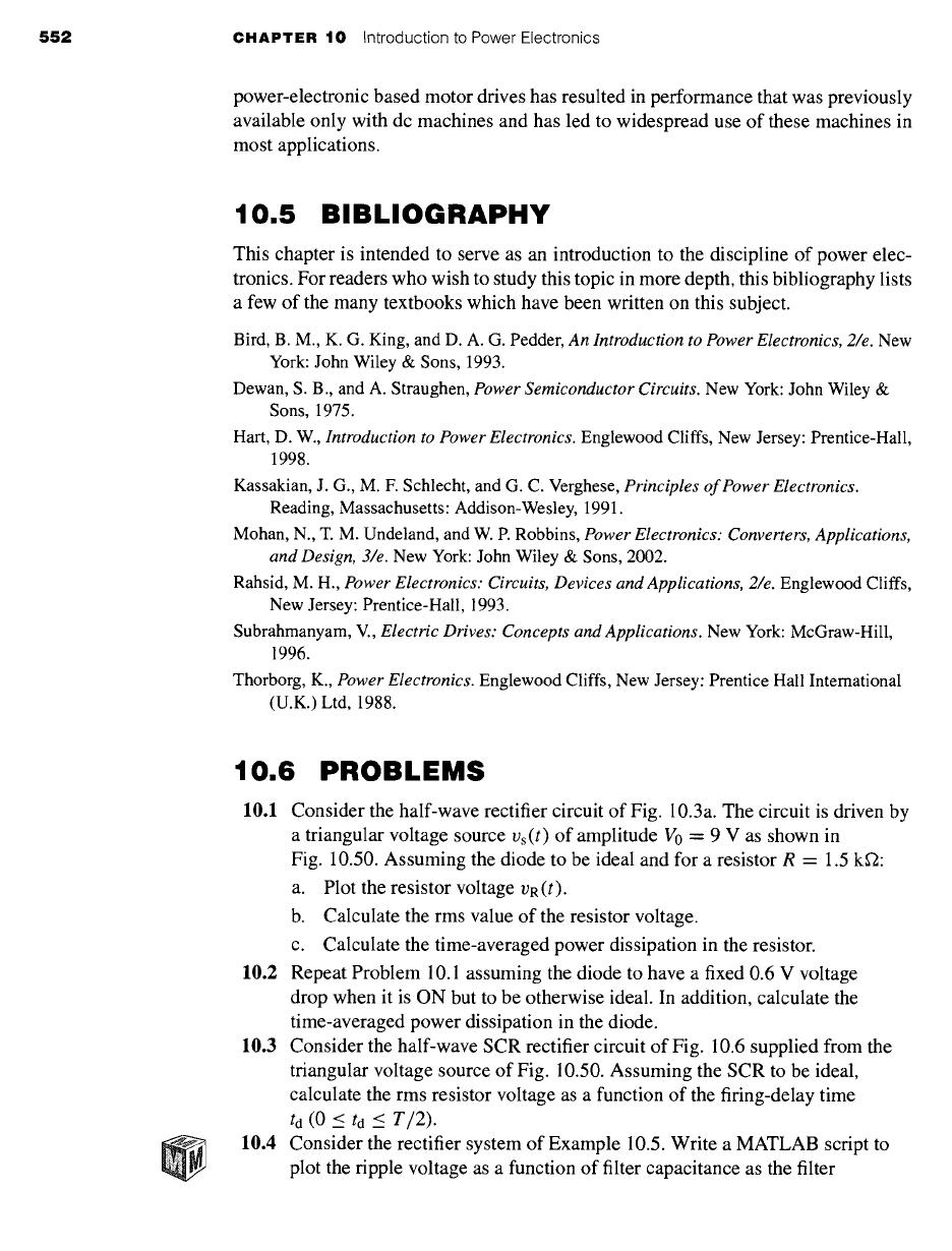
Vo
Figure
10.50 Triangular voltage waveform.
capacitance is varied over the range 3000/xF < C < 105/xF. Assume the
diode to be ideal. Use a log-scale for the capacitance.
10.5 Consider the full-wave rectifier system of Fig. 10.16 with R = 500 fl and
C -- 200/xF. Assume each diode to have a constant voltage drop of 0.7 V
when it is ON but to be otherwise ideal. For a 220 V rms, 50 Hz sinusoidal
source, write a MATLAB script to calculate
a. the peak voltage across the load resistor.
b. the magnitude of the ripple voltage.
c. the time-averaged power supplied to the load resistor.
d. the time-averaged power dissipation in the diode bridge.
10.6 Consider the half-wave rectifier system of Fig. 10.51. The voltage source
is Vs(t) -- V0 sin oot where V0 = 15 V, and the frequency is 100 Hz. For
L = 1 mH and R = 1 S2, plot the inductor current iL(t) for the first 1-1/2
cycles of the applied waveform assuming the switch closes at time t = 0.
10.7 Repeat Problem 10.6, using MATLAB to plot the inductor current for the first
10 cycles following the switch closing at time t -- 0. (Hint: This problem
can be easily solved, using simple Euler integration to solve for the current.)
Switch
+ o,L
Vs(t)_ D2 i
Figure 10.51
Problem 10.6.
Half-wave rectifier system for
554
CHAPTER 10 Introduction to Power Electronics
is(t)
D1 ~ iL(t)
+ + R
Vs(t) D2
V~s(t) +
-- -- L v(t)
m
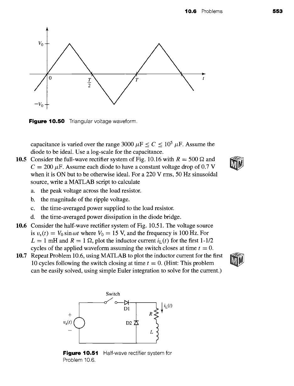
Figure 10.52
Half-wave rectifier system
for Problem 10.8.
10.8 Consider the half-wave rectifier system of Fig. 10.52 as L becomes
sufficiently large such that co (L/R) >> 1, where co is the supply frequency. In
this case, the inductor current will be essentially constant. For R - 5 f2 and
Vs(t) = V0 sin cot where V0 = 45 V and co = 100zr rad/sec. Assume the
diodes to be ideal.
a. Calculate the average (dc) value Vdc of the voltage v' s (t) across the series
resistor/inductor combination.
b. Using the fact that, in the steady state, there will be zero average voltage
across the inductor, calculate the dc inductor current Idc.
c. Plot the instantaneous inductor voltage
v(t)
over one cycle of the supply
voltage.
d. Plot the instantaneous source current is(t).
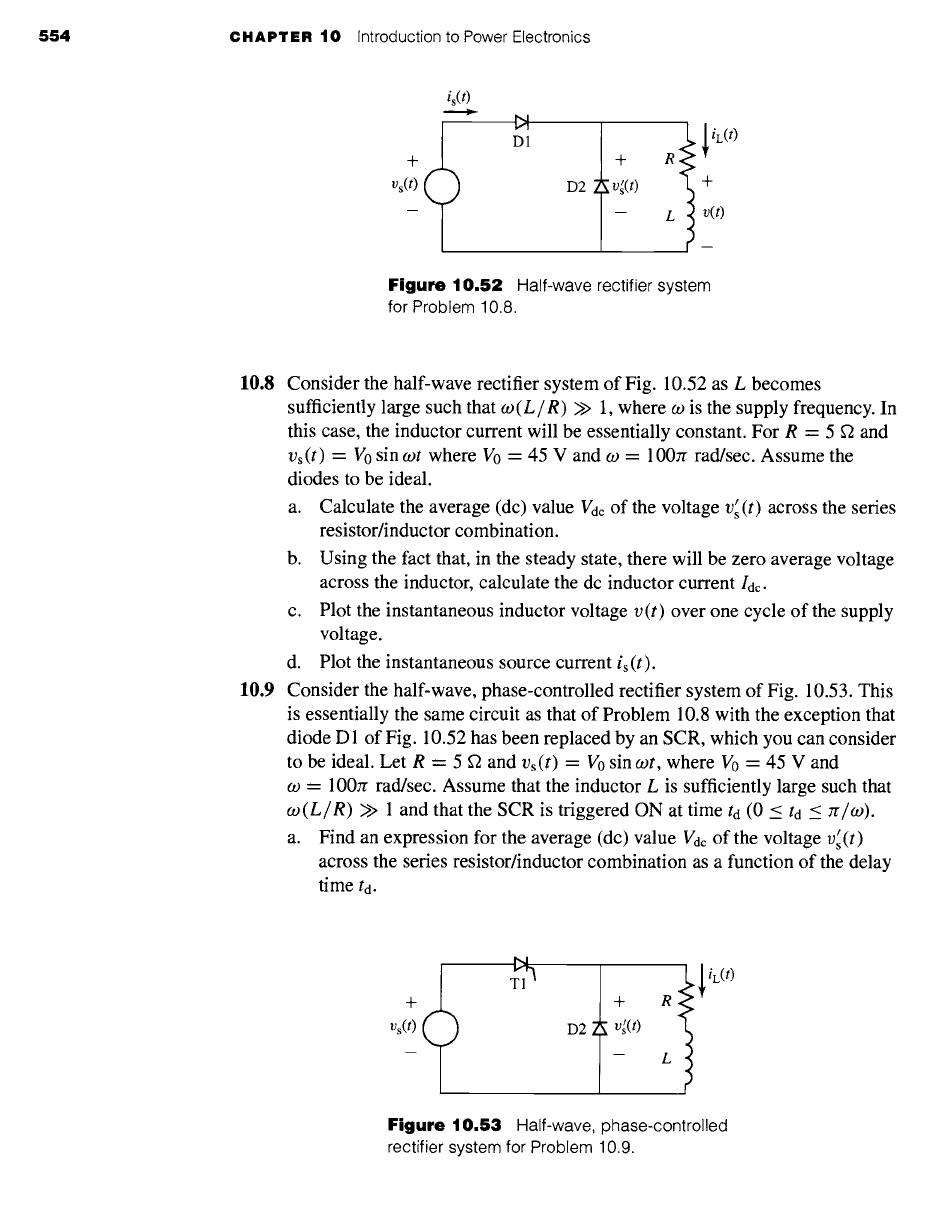
10.9 Consider the half-wave, phase-controlled rectifier system of Fig. 10.53. This
is essentially the same circuit as that of Problem 10.8 with the exception that
diode D 1 of Fig. 10.52 has been replaced by an SCR, which you can consider
to be ideal. Let R = 5 ~ and Vs(t) = V0 sin cot, where V0 = 45 V and
co - 100zr rad/sec. Assume that the inductor L is sufficiently large such that
co(L/R)
>> 1 and that the SCR is triggered ON at time td (0 < td < It/co).
a. Find an expression for the average (dc) value Vdc of the voltage v~ (t)
across the series resistor/inductor combination as a function of the delay
time to.
b
~ iL(t)
+ + R
Vs(t) D2 v~(t)
-- -- t
Figure 10.53
Half-wave, phase-controlled
rectifier system for Problem 10.9.
10.6 Problems 555
+
Vs(t)
m
T1 5
D2 2
L
f
~, D35
'"JI-
v~(t)
R
L
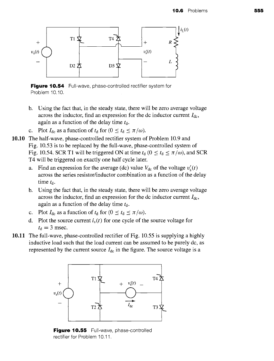
Figure 10.54 Full-wave, phase-controlled rectifier system for
Problem 10.10.
iL(t)
b. Using the fact that, in the steady state, there will be zero average voltage
across the inductor, find an expression for the dc inductor current Idc,
again as a function of the delay time td.
c. Plot Idc as a function of td for (0 < td < re/W).
10.10 The half-wave, phase-controlled rectifier system of Problem 10.9 and
Fig. 10.53 is to be replaced by the full-wave, phase-controlled system of
Fig. 10.54. SCR T1 will be triggered ON at time ta (0 < td < re/co), and SCR
T4 will be triggered on exactly one half cycle later.
a. Find an expression for the average (dc) value Vdc of the voltage v~ (t)
across the series resistor/inductor combination as a function of the delay
time td.
b. Using the fact that, in the steady state, there will be zero average voltage
across the inductor, find an expression for the dc inductor current Idc,
again as a function of the delay time td.
c. Plot Idc as a function of td for (0 < td _< re/co).
d. Plot the source current is(t) for one cycle of the source voltage for
td = 3 msec.
10.11 The full-wave, phase-controlled rectifier of Fig. 10.55 is supplying a highly
inductive load such that the load current can be assumed to be purely dc, as
represented by the current source Idc in the figure. The source voltage is a
+
Vs(t) (
)
TI~_
L
+ v[(t)_
G
Idc
T3
L
Figure 10.55 Full-wave, phase-controlled
rectifier for Problem 10.11.