Fitzgerald A.E. Electric Machinery
Подождите немного. Документ загружается.

Preface xv
Alexander E. Koutras,
California Polytechnic State University, Pomona
Bruno Osorno,
California State University, Northridge
Henk Polinder,
Delft University of Technology
Gill Richards,
Arkansas Tech University
Duane E Rost,
Youngstown State University
Melvin Sandler,
The Cooper Union
Ali O. Shaban,
California Polytechnic State University, San Luis Obispo
Alan Wallace,
Oregon State University
I would like to specifically acknowledge Professor Ibrahim Abdel-Moneim Abdel-
Halim of Zagazig University, whose considerable effort found numerous typos and
numerical errors in the draft document.
Stephen D. Umans
Cambridge, MA
March 5, 2002
BRIEF CONTENTS
Preface x
1 Magnetic Circuits and Magnetic Materials 1
2 Transformers 57
3 Electromechanical-Energy-ConversionPrinciples 112
4 Introduction to Rotating Machines 173
5 Synchronous Machines 245
6 Polyphase Induction Machines 306
7 DCMachines 357
8 Variable-Reluctance Machines and Stepping Motors 407
9 Single- and Two-Phase Motors 452
10 Introduction to Power Electronics 493
11 Speed and Torque Control 559
Appendix A Three-Phase Circuits 628
Appendix B Voltages, Magnetic Fields, and Inductances
of Distributed AC Windings 644
Appendix C The dq0 Transformation 657
Appendix D Engineering Aspects of Practical Electric Machine
Performance and Operation 668
Appendix E Table of Constants and Conversion
Factors for SI Units 680
Index 681
vi
CONTENTS
Preface x
ChaDter
1
Magnetic Circuits and Magnetic
Materials 1
1.1 Introduction to Magnetic Circuits 2
1.2 Flux Linkage, Inductance, and Energy
1.3 Properties of Magnetic Materials 19
1.4 AC Excitation 23
1.5 Permanent Magnets 30
1.6 Application of Permanent Magnet
Materials 35
1.7 Summary 42
1.8 Problems 43
11
Chapter
2
Transformers
2.1
2.2
2.3
2.4
2.5
2.6
2.7
2.8
2.9
2.10 Summary
2.11 Problems
57
Introduction to Transformers 57
No-Load Conditions 60
Effect of Secondary Current; Ideal
Transformer 64
Transformer Reactances and Equivalent
Circuits 68
Engineering Aspects of Transformer
Analysis 73
Autotransformers; Multiwinding
Transformers 81
Transformers in Three-Phase Circuits
Voltage and Current Transformers 90
The Per-Unit System 95
103
104
85
3.1
3.2
3.3
3.4
3.5
3.6
3.7
3.8
3.9
3.10 Summary
3.11 Problems
Chapter 3
Electromechanical-
Energy-Conversion
Principles 112
Forces and Torques in Magnetic
Field Systems 113
Energy Balance 117
Energy in Singly-Excited Magnetic Field
Systems 119
Determination of Magnetic Force and Torque
from Energy 123
Determination of Magnetic Force and Torque
from Coenergy 129
Multiply-Excited Magnetic Field
Systems 136
Forces and Torques in Systems with
Permanent Magnets 142
Dynamic Equations 151
Analytical Techniques 155
158
159
Chapter 4
Introduction to Rotating
Machines 173
4.1 Elementary Concepts 173
4.2 Introduction to AC and DC Machines
4.3 MMF of Distributed Windings 187
4.4 Magnetic Fields in Rotating Machinery
4.5 Rotating MMF Waves in AC Machines
4.6 Generated Voltage 208
4.7 Torque in Nonsalient-Pole Machines
4.8 Linear Machines 227
4.9 Magnetic Saturation 230
176
197
201
214
VII
viii
Contents
4.10
Leakage Fluxes
4.11 Summary 235
4.12 Problems 237
233
Chapter 5
Synchronous Machines
245
5.1 Introduction to Polyphase Synchronous
Machines 245
5.2 Synchronous-Machine Inductances;
Equivalent Circuits 248
5.3 Open- and Short-Circuit Characteristics
5.4 Steady-State Power-Angle
Characteristics 266
5.5 Steady-State Operating Characteristics
5.6 Effects of Salient Poles; Introduction to
5.7
5.8
5.9
5.10 Problems
256
275
Direct- and Quadrature-Axis Theory 281
Power-Angle Characteristics of Salient-Pole
Machines 289
Permanent-Magnet AC Motors 293
Summary 295
297
Chapter 6
Polyphase Induclion
Machines
306
6.1 Introduction to Polyphase Induction
Machines 306
6.2 Currents and Fluxes in Polyphase Induction
Machines 311
6.3 Induction-Motor Equivalent Circuit 313
6.4 Analysis of the Equivalent Circuit 317
6.5 Torque and Power by Use of Thevenin's
Theorem 322
6.6 Parameter Determination from No-Load and
Blocked-Rotor Tests 330
6.7 Effects of Rotor Resistance; Wound and
Double-Squirrel-Cage Rotors 340
6.8 Summary 347
6.9 Problems 348
Chapter 7
DC Machines
357
7.1
7.2
7.3
7.4
7.5
7.6
7.7
7.8
7.9
7.10 Series Universal Motors
7.11 Summary 396
7.12 Problems 397
Introduction 357
Commutator Action 364
Effect of Armature MMF 367
Analytical Fundamentals: Electric-Circuit
Aspects 370
Analytical Fundamentals: Magnetic-Circuit
Aspects 374
Analysis of Steady-State Performance 379
Permanent-Magnet DC Machines 384
Commutation and Interpoles 390
Compensating Windings 393
395
Chapter 8
Variable-Reluctance Machines and
Stepping Motors
407
8.1 Basics of VRM Analysis 408
8.2 Practical VRM Configurations 415
8.3 Current Waveforms for Torque Production 421
8.4 Nonlinear Analysis 430
8.5 Stepping Motors 437
8.6 Summary 446
8.7 Problems 448
Chapter 9
Single- and Two.Phase Motors
452
9.1 Single-Phase Induction Motors: Qualitative
Examination 452
9.2 Starting and Running Performance of Single-
Phase Induction and Synchronous Motors
455
9.3 Revolving-Field Theory of Single-Phase
Induction Motors 463
9.4 Two-Phase Induction Motors 470
Contents ix
9.5 Summary 488
9.6 Problems 489
Chapter 10
Introduction to Power
Electronics
493
10.l Power Switches 494
10.2 Rectification: Conversion of AC to DC 507
10.3 Inversion: Conversion of DC to AC 538
10.4 Summary 550
10.5 Bibliography 552
10.6 Problems 552
Chapter 1 1
Speed and Torque Control
559
11.1 Control of DC Motors 559
11.2 Control of Synchronous Motors 578
11.3 Control of Induction Motors 595
11.4 Control of Variable-Reluctance Motors
11.5 Summary 616
11.6 Bibliography 618
11.7 Problems 618
613
APPendix A
, ,
Three.Phase Circuits
628
A.1 Generation of Three-Phase Voltages 628
A.2 Three-Phase Voltages, Currents, and
Power 631
A.3 Y- and A-Connected Circuits 635
A.4 Analysis of Balanced Three-Phase Circuits;
Single-Line Diagrams 641
A.5 Other Polyphase Systems 643
Appendix
B
, ,
Voltages, Magnetic Fields, and
Inductances of Distributed
AC Windings 644
B.1 Generated Voltages 644
B.2 Armature MMF Waves 650
B.3 Air-Gap Inductances of Distributed
Windings 653
Appendix C
, ,
The dqO Transformation
657
C.1 Transformation to Direct- and Quadrature-Axis
Variables 657
C.2 Basic Synchronous-Machine Relations in dq0
Variables 660
C.3 Basic Induction-Machine Relations in dq0
Variables 664
Appendix
D
, ,
Engineering Aspects of Practical
Electric Machine Performance
and Operation
668
D.I Losses 668
D.2 Rating and Heating 670
D.3 Cooling Means for Electric Machines 674
D.4 Excitation 676
D.5 Energy Efficiency of Electric Machinery 678
ADDendix E
, ,
Table of Constants and Conversion
Factors for Sl Units 680
Index 681
Magnetic Circuits and
Magnetic Materials
T
he objective of this book is to study the devices used in the interconversion
of electric and mechanical energy. Emphasis is placed on electromagnetic
rotating machinery, by means of which the bulk of this energy conversion
takes place. However, the techniques developed are generally applicable to a wide
range of additional devices including linear machines, actuators, and sensors.
Although not an electromechanical-energy-conversion device, the transformer is
an important component of the overall energy-conversion process and is discussed in
Chapter 2. The techniques developed for transformer analysis form the basis for the
ensuing discussion of electric machinery.
Practically all transformers and electric machinery use ferro-magnetic material
for shaping and directing the magnetic fields which act as the medium for transfer-
ring and converting energy. Permanent-magnet materials are also widely used. With-
out these materials, practical implementations of most familiar electromechanical-
energy-conversion devices would not be possible. The ability to analyze and describe
systems containing these materials is essential for designing and understanding these
devices.
This chapter will develop some basic tools for the analysis of magnetic field
systems and will provide a brief introduction to the properties of practical magnetic
materials. In Chapter 2, these results will then be applied to the analysis of transform-
ers. In later chapters they will be used in the analysis of rotating machinery.
In this book it is assumed that the reader has basic knowledge of magnetic
and electric field theory such as given in a basic physics course for engineering
students. Some readers may have had a course on electromagnetic field theory based
on Maxwell's equations, but an in-depth understanding of Maxwell's equations is
not a prerequisite for study of this book. The techniques of magnetic-circuit analysis,
which represent algebraic approximations to exact field-theory solutions, are widely
used in the study of electromechanical-energy-conversion devices and form the basis
for most of the analyses presented here.
2 CHAPTER 1 Magnetic Circuits and Magnetic Materials
1.1 INTRODUCTION TO MAGNETIC CIRCUITS
The complete, detailed solution for magnetic fields in most situations of practical
engineering interest involves the solution of Maxwell's equations along with various
constitutive relationships which describe material properties. Although in practice
exact solutions are often unattainable, various simplifying assumptions permit the
attainment of useful engineering solutions. 1
We begin with the assumption that, for the systems treated in this book, the fre-
quencies and sizes involved are such that the displacement-current term in Maxwell's
equations can be neglected. This term accounts for magnetic fields being produced
in space by time-varying electric fields and is associated with electromagnetic ra-
diation. Neglecting this term results in the magneto-quasistatic form of the relevant
Maxwell's equations which relate magnetic fields to the currents which produce
them.
IB. da - 0 (1.2)
Equation 1.1 states that the line integral of the tangential component of the
magnetic field intensity
H around a closed contour C is equal to the total current
passing through any surface S linking that contour. From Eq. 1.1 we see that the source
of H is the
current density
J. Equation 1.2 states that the
magnetic flux density
B is
conserved, i.e., that no net flux enters or leaves a closed surface (this is equivalent to
saying that there exist no monopole charge sources of magnetic fields). From these
equations we see that the magnetic field quantities can be determined solely from the
instantaneous values of the source currents and that time variations of the magnetic
fields follow directly from time variations of the sources.
A second simplifying assumption involves the concept of the
magnetic cir-
cuit.
The general solution for the magnetic field intensity H and the magnetic flux
density B in a structure of complex geometry is extremely difficult. However, a
three-dimensional field problem can often be reduced to what is essentially a one-
dimensional circuit equivalent, yielding solutions of acceptable engineering accuracy.
A magnetic circuit consists of a structure composed for the most part of high-
permeability magnetic material. The presence of high-permeability material tends to
cause magnetic flux to be confined to the paths defined by the structure, much as
currents are confined to the conductors of an electric circuit. Use of this concept of
I Although exact analytical solutions cannot be obtained, computer-based numerical solutions (the
finite-element and boundary-element methods form the basis for a number of commercial programs) are
quite common and have become indespensible tools for analysis and design. However, such techniques
are best used to refine analyses based upon analytical techniques such as are found in this book. Their use
contributes little to a fundamental understanding of the principles and basic performance of electric
machines and as a result they will not be discussed in this book.
1,1 Introduction to Magnetic Circuits 8
Mean core
length l c
Cross-sectional
area A c
Wit Magnetic core
N1 permeability/z
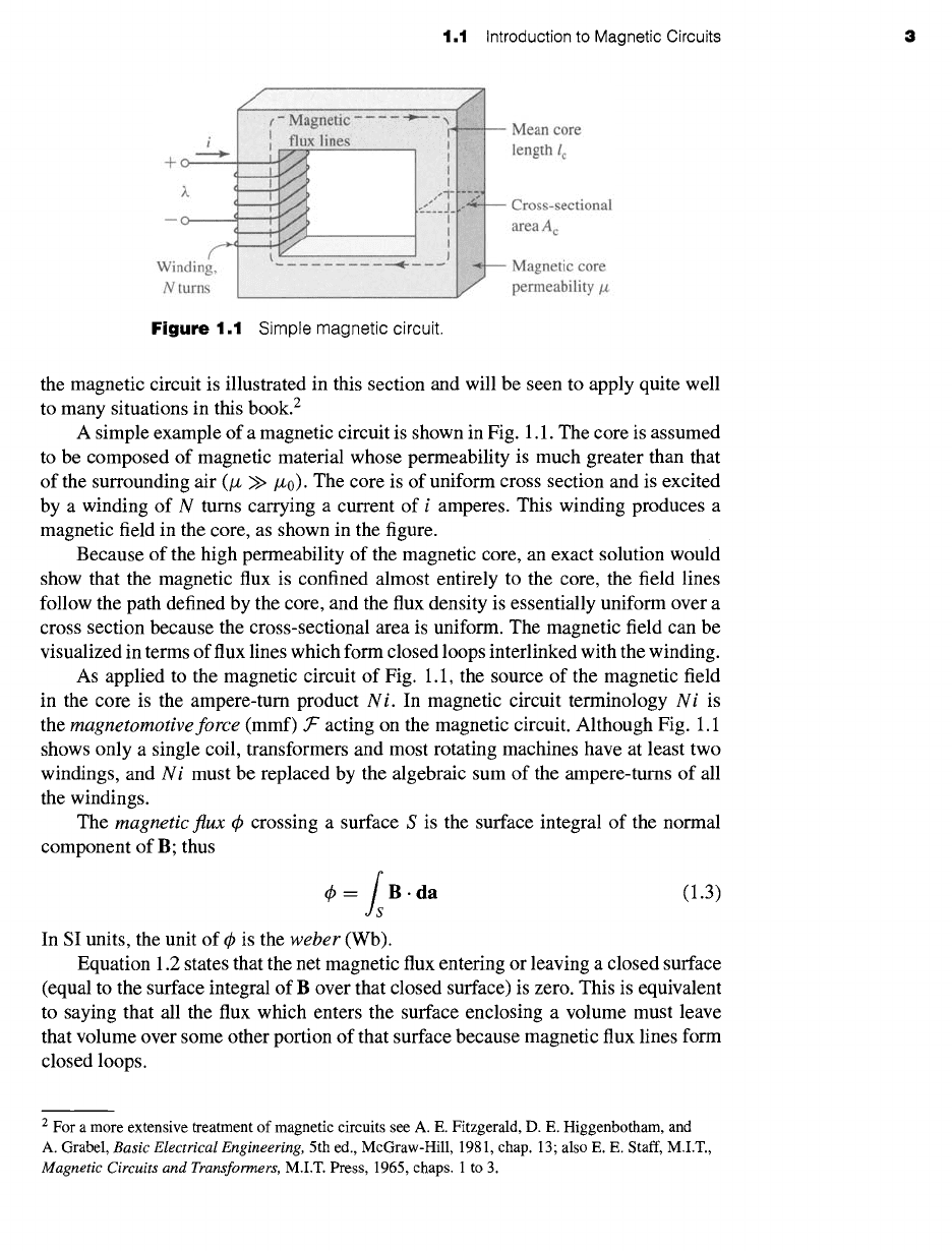
Figure
1.1 Simple magnetic circuit.
the magnetic circuit is illustrated in this section and will be seen to apply quite well
to many situations in this book. 2
A simple example of a magnetic circuit is shown in Fig. 1.1. The core is assumed
to be composed of magnetic material whose permeability is much greater than that
of the surrounding air (/z >>/z0). The core is of uniform cross section and is excited
by a winding of N turns carrying a current of i amperes. This winding produces a
magnetic field in the core, as shown in the figure.
Because of the high permeability of the magnetic core, an exact solution would
show that the magnetic flux is confined almost entirely to the core, the field lines
follow the path defined by the core, and the flux density is essentially uniform over a
cross section because the cross-sectional area is uniform. The magnetic field can be
visualized in terms of flux lines which form closed loops interlinked with the winding.
As applied to the magnetic circuit of Fig. 1.1, the source of the magnetic field
in the core is the ampere-turn product
N i.
In magnetic circuit terminology
N i
is
the
magnetomotive force
(mmf) .T" acting on the magnetic circuit. Although Fig. 1.1
shows only a single coil, transformers and most rotating machines have at least two
windings, and
N i
must be replaced by the algebraic sum of the ampere-turns of all
the windings.
The
magnetic flux ¢
crossing a surface S is the surface integral of the normal
component of B; thus
¢ =/IB .da (1.3)
In SI units, the unit of ¢ is the
weber
(Wb).
Equation 1.2 states that the net magnetic flux entering or leaving a closed surface
(equal to the surface integral of B over that closed surface) is zero. This is equivalent
to saying that all the flux which enters the surface enclosing a volume must leave
that volume over some other portion of that surface because magnetic flux lines form
closed loops.
2 For a more extensive treatment of magnetic circuits see A. E. Fitzgerald, D. E. Higgenbotham, and
A. Grabel,
Basic Electrical Engineering,
5th ed., McGraw-Hill, 1981, chap. 13; also E. E. Staff, M.I.T.,
Magnetic Circuits and Transformers,
M.I.T. Press, 1965, chaps. 1 to 3.
4 CHAPTER 1
Magnetic Circuits and Magnetic Materials
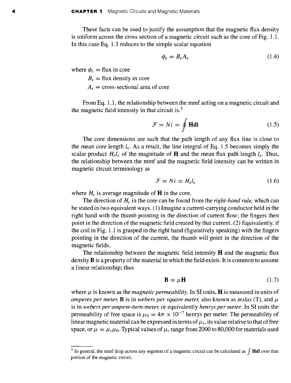
These facts can be used to justify the assumption that the magnetic flux density
is uniform across the cross section of a magnetic circuit such as the core of Fig. 1.1.
In this case Eq. 1.3 reduces to the simple scalar equation
~bc = Bc Ac (1.4)
where 4)c = flux in core
Bc = flux density in core
Ac = cross-sectional area of core
From Eq. 1.1, the relationship between the mmf acting on a magnetic circuit and
the magnetic field intensity in that circuit is. 3
-- Ni -- / Hdl (1.5)
The core dimensions are such that the path length of any flux line is close to
the mean core length lc. As a result, the line integral of Eq. 1.5 becomes simply the
scalar product Hclc of the magnitude of H and the mean flux path length Ic. Thus,
the relationship between the mmf and the magnetic field intensity can be written in
magnetic circuit terminology as
= Ni -- Hclc (1.6)
where Hc is average magnitude of H in the core.
The direction of Hc in the core can be found from the right-hand rule, which can
be stated in two equivalent ways. (1) Imagine a current-carrying conductor held in the
right hand with the thumb pointing in the direction of current flow; the fingers then
point in the direction of the magnetic field created by that current. (2) Equivalently, if
the coil in Fig. 1.1 is grasped in the right hand (figuratively speaking) with the fingers
pointing in the direction of the current, the thumb will point in the direction of the
magnetic fields.
The relationship between the magnetic field intensity H and the magnetic flux
density B is a property of the material in which the field exists. It is common to assume
a linear relationship; thus
B = #H (1.7)
where # is known as the magnetic permeability. In SI units, H is measured in units of
amperes per meter, B is in webers per square meter, also known as teslas (T), and/z
is in webers per ampere-turn-meter, or equivalently henrys per meter. In SI units the
permeability of free space is #0 = 4:r × 10 -7 henrys per meter. The permeability of
linear magnetic material can be expressed in terms of/Zr, its value relative to that of free
space, or # = #r#0. Typical values of/Z
r
range from 2000 to 80,000 for materials used
3
general, the mmf drop across any segment of a magnetic circuit can be calculated as f I-Idl over
In that
portion of the magnetic circuit.
1,1 Introduction to Magnetic Circuits 5
Mean core
length I c
+
Air gap,
permeability/x 0,
Area Ag
Wi~ Magnetic core
N1 permeability/z,
Area A c
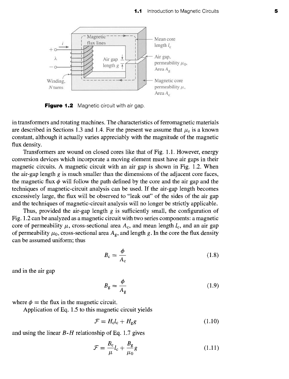
Figure
1.2 Magnetic circuit with air gap.
in transformers and rotating machines. The characteristics of ferromagnetic materials
are described in Sections 1.3 and 1.4. For the present we assume that/Zr is a known
constant, although it actually varies appreciably with the magnitude of the magnetic
flux density.
Transformers are wound on closed cores like that of Fig. 1.1. However, energy
conversion devices which incorporate a moving element must have air gaps in their
magnetic circuits. A magnetic circuit with an air gap is shown in Fig. 1.2. When
the air-gap length g is much smaller than the dimensions of the adjacent core faces,
the magnetic flux ~ will follow the path defined by the core and the air gap and the
techniques of magnetic-circuit analysis can be used. If the air-gap length becomes
excessively large, the flux will be observed to "leak out" of the sides of the air gap
and the techniques of magnetic-circuit analysis will no longer be strictly applicable.
Thus, provided the air-gap length g is sufficiently small, the configuration of
Fig. 1.2 can be analyzed as a magnetic circuit with two series components: a magnetic
core of permeability/~, cross-sectional area Ac, and mean length/c, and an air gap
of permeability/z0, cross-sectional
area Ag,
and length g. In the core the flux density
can be assumed uniform; thus
Bc = m (1.8)
Ac
and in the air gap
~b (1.9)
Bg- Ag
where 4~ = the flux in the magnetic circuit.
Application of Eq. 1.5 to this magnetic circuit yields
jr = Hctc +
Egg
and using the linear
B-H
relationship of Eq. 1.7 gives
.T'= BClc_}_ Bg g
lZ lZo
(1.10)
(1.11)