Fitzgerald A.E. Electric Machinery
Подождите немного. Документ загружается.

46 CHAPTER 1 Magnetic Circuits and Magnetic Materials
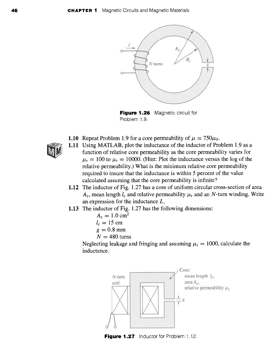
Figure 1.26
Magnetic circuit for
Problem 1.9.
1.10 Repeat Problem 1.9 for a core permeability of/z = 750/z0.
1.11 Using MATLAB, plot the inductance of the inductor of Problem 1.9 as a
function of relative core permeability as the core permeability varies for
/z r = 100 to/Zr = 10000. (Hint: Plot the inductance versus the log of the
relative permeability.) What is the minimum relative core permeability
required to insure that the inductance is within 5 percent of the value
calculated assuming that the core permeability is infinite?
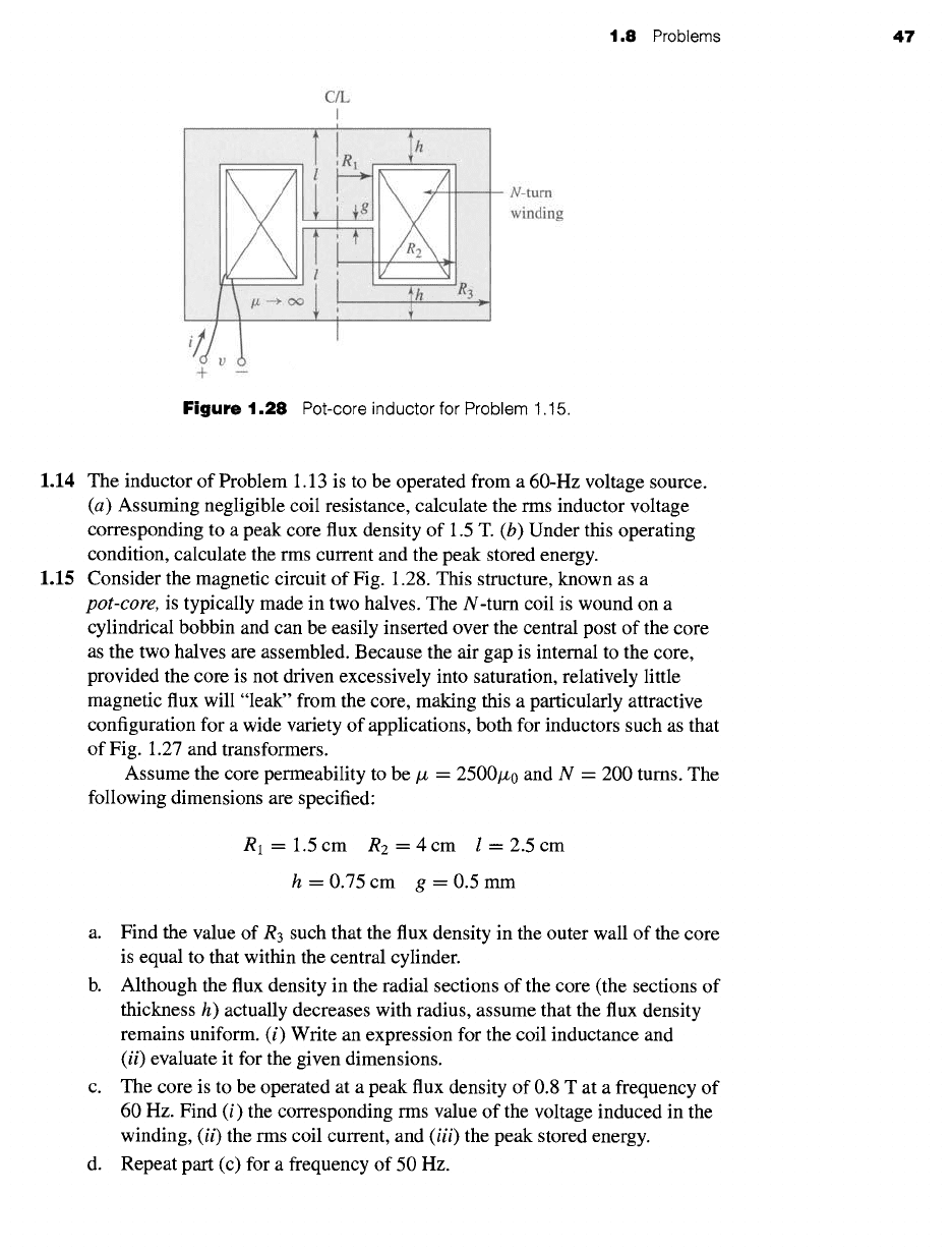
1.12 The inductor of Fig. 1.27 has a core of uniform circular cross-section of area
Ac, mean length lc and relative permeability/Zr and an N-turn winding. Write
an expression for the inductance L.
1.13 The inductor of Fig. 1.27 has the following dimensions:
Ac = 1.0 cm 2
lc = 15 cm
g = 0.8 mm
N = 480 turns
Neglecting leakage and fringing and assuming
#r --
1000, calculate the
inductance.
N-turn
coil
v/Core:
j] mean length /c,
area A c,
, relative permeability #r
Figure 1.27
Inductor for Problem 1.12.
1.8 Problems 47
C/L
I
+
N-tum
winding
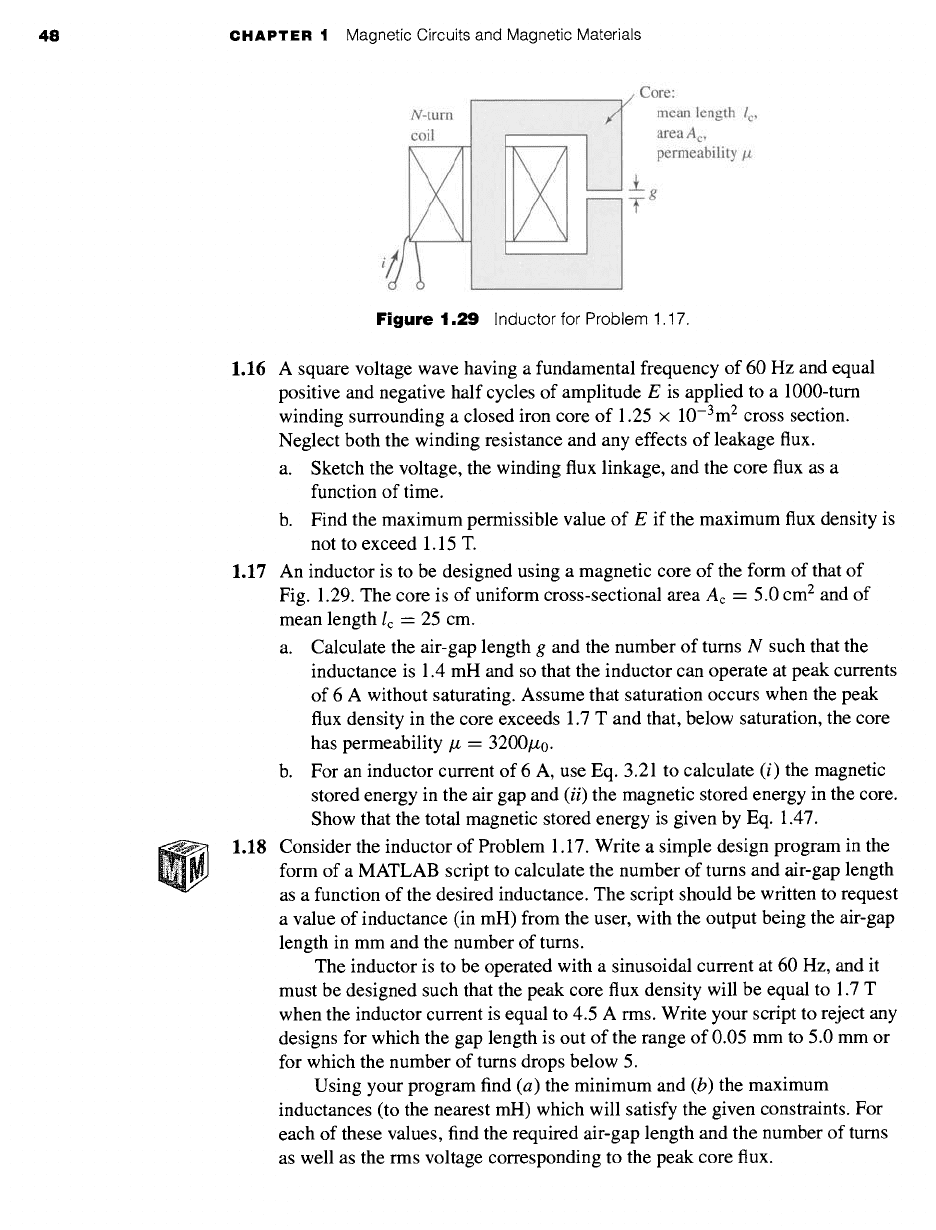
Figure
1.28 Pot-core inductor for Problem 1.15.
1.14 The inductor of Problem 1.13 is to be operated from a 60-Hz voltage source.
(a) Assuming negligible coil resistance, calculate the rms inductor voltage
corresponding to a peak core flux density of 1.5 T. (b) Under this operating
condition, calculate the rms current and the peak stored energy.
1.15 Consider the magnetic circuit of Fig. 1.28. This structure, known as a
pot-core,
is typically made in two halves. The N-turn coil is wound on a
cylindrical bobbin and can be easily inserted over the central post of the core
as the two halves are assembled. Because the air gap is internal to the core,
provided the core is not driven excessively into saturation, relatively little
magnetic flux will "leak" from the core, making this a particularly attractive
configuration for a wide variety of applications, both for inductors such as that
of Fig. 1.27 and transformers.
Assume the core permeability to be/z = 2500/z0 and N = 200 turns. The
following dimensions are specified:
R l= 1.5cm R2=4cm l=2.5cm
h=0.75cm g=0.5mm
a. Find the value of R3 such that the flux density in the outer wall of the core
is equal to that within the central cylinder.
b. Although the flux density in the radial sections of the core (the sections of
thickness h) actually decreases with radius, assume that the flux density
remains uniform. (i) Write an expression for the coil inductance and
(ii)
evaluate it for the given dimensions.
c. The core is to be operated at a peak flux density of 0.8 T at a frequency of
60 Hz. Find (i) the corresponding rms value of the voltage induced in the
winding,
(ii)
the rms coil current, and
(iii)
the peak stored energy.
d. Repeat part (c) for a frequency of 50 Hz.
48 CHAPTER 1 Magnetic Circuits and Magnetic Materials
Core:
mean length
l c,
area A c,
permeability/z
L
g
F
Figure
1.29 Inductor for Problem 1.17.
1.16 A square voltage wave having a fundamental frequency of 60 Hz and equal
positive and negative half cycles of amplitude E is applied to a 1000-turn
winding surrounding a closed iron core of 1.25 x 10⁻³m 2 cross section.
Neglect both the winding resistance and any effects of leakage flux.
a. Sketch the voltage, the winding flux linkage, and the core flux as a
function of time.
b. Find the maximum permissible value of E if the maximum flux density is
not to exceed 1.15 T.
1.17 An inductor is to be designed using a magnetic core of the form of that of
Fig. 1.29. The core is of uniform cross-sectional area Ac = 5.0 cm 2 and of
mean length Ic = 25 cm.
a. Calculate the air-gap length g and the number of turns N such that the
inductance is 1.4 mH and so that the inductor can operate at peak currents
of 6 A without saturating. Assume that saturation occurs when the peak
flux density in the core exceeds 1.7 T and that, below saturation, the core
has permeability/z = 3200/z0.
b. For an inductor current of 6 A, use Eq. 3.21 to calculate (i) the magnetic
stored energy in the air gap and
(ii)
the magnetic stored energy in the core.
Show that the total magnetic stored energy is given by Eq. 1.47.
1.18 Consider the inductor of Problem 1.17. Write a simple design program in the
form of a MATLAB script to calculate the number of turns and air-gap length
as a function of the desired inductance. The script should be written to request
a value of inductance (in mH) from the user, with the output being the air-gap
length in mm and the number of turns.
The inductor is to be operated with a sinusoidal current at 60 Hz, and it
must be designed such that the peak core flux density will be equal to 1.7 T
when the inductor current is equal to 4.5 A rms. Write your script to reject any
designs for which the gap length is out of the range of 0.05 mm to 5.0 mm or
for which the number of turns drops below 5.
Using your program find (a) the minimum and (b) the maximum
inductances (to the nearest mH) which will satisfy the given constraints. For
each of these values, find the required air-gap length and the number of turns
as well as the rms voltage corresponding to the peak core flux.
1.8 Problems 49
Figure
1.30 Toroidal winding for Problem 1.19.
1.19 A proposed energy storage mechanism consists of an N-turn coil wound
around a large nonmagnetic (/z -/~0) toroidal form as shown in Fig. 1.30. As
can be seen from the figure, the toroidal form has a circular cross section of
radius a and toroidal radius r, measured to the center of the cross section. The
geometry of this device is such that the magnetic field can be considered to be
zero everywhere outside the toroid. Under the assumption that a << r, the H
field inside the toroid can be considered to be directed around the toroid and
of uniform magnitude
Ni
2rc r
For a coil with N = 1000 turns, r = 10 m, and a = 0.45 m:
a. Calculate the coil inductance L.
b. The coil is to be charged to a magnetic flux density of 1.75 T. Calculate
the total stored magnetic energy in the toms when this flux density is
achieved.
c. If the coil is to be charged at a uniform rate (i.e.,
di/dt
= constant),
calculate the terminal voltage required to achieve the required flux density
in 30 sec. Assume the coil resistance to be negligible.
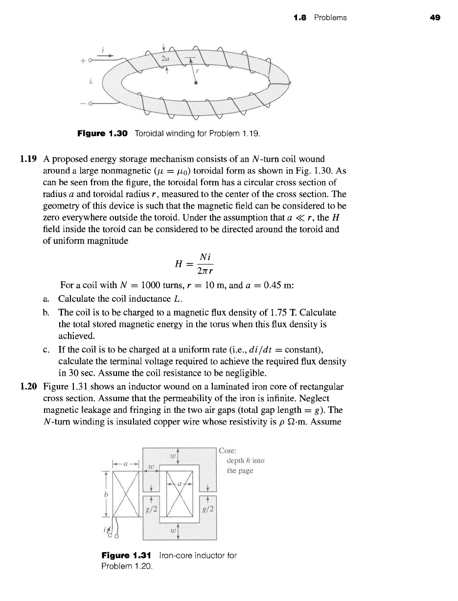
1.20 Figure 1.31 shows an inductor wound on a laminated iron core of rectangular
cross section. Assume that the permeability of the iron is infinite. Neglect
magnetic leakage and fringing in the two air gaps (total gap length = g). The
N-turn winding is insulated copper wire whose resistivity is p ~.m. Assume
iiiiiiiiiiiiiiiiiliiiiiii i iiiiiiiiiiii~il!iiiiiiili!!iiiiiiiiiiiiiiiiil i iiii! iiiiiii!ii!
i
Core:
depth h into
the page
Figure 1.31
Iron-core inductor for
Problem 1.20.
50
CHAPTER 1 Magnetic Circuits and Magnetic Materials
that the fraction fw of the winding space is available for copper; the rest of the
space is used for insulation.
a. Calculate the cross-sectional area and volume of the copper in the
winding space.
b. Write an expression for the flux density B in the inductor in terms of the
current density Jcu in the copper winding.
c. Write an expression for the copper current density Jcu in terms of the coil
current I, the number of turns N, and the coil geometry.
d. Derive an expression for the electric power dissipation in the coil in terms
of the current density Jcu.
e. Derive an expression for the magnetic stored energy in the inductor in
terms of the applied current density Jcu.
f. From parts (d) and (e) derive an expression for the
L/R
time constant of
the inductor. Note that this expression is independent of the number of
turns in the coil and does not change as the inductance and coil resistance
are changed by varying the number of turns.
1.21 The inductor of Fig. 1.31 has the following dimensions:
a--h=w---1.5cm b=2cm g=0.2cm
The winding factor (i.e., the fraction of the total winding area occupied
by conductor) is fw = 0.55. The resistivity of copper is 1.73 × 10 -8 S2.m.
When the coil is operated with a constant dc applied voltage of 35 V, the
air-gap flux density is measured to be 1.4 T. Find the power dissipated in the
coil, coil current, number of turns, coil resistance, inductance, time constant,
and wire size to the nearest standard size. (Hint: Wire size can be found from
the expression
( Awire )
AWG=36-4.3121n 1.267× l0 -8
where AWG is the wire size, expressed in terms of the American Wire Gauge,
and
Awire
is the conductor cross-sectional area measured in me.)
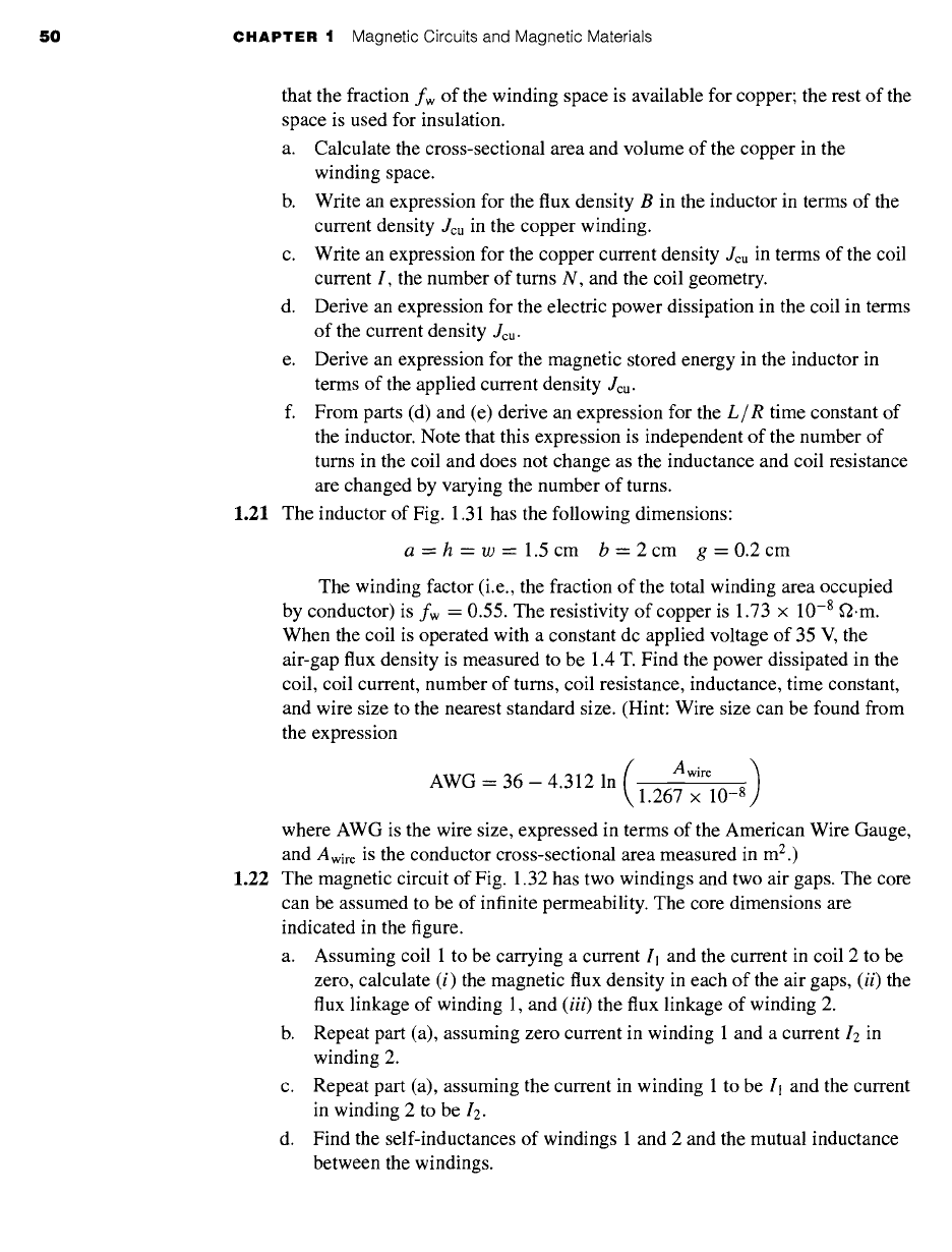
1.22 The magnetic circuit of Fig. 1.32 has two windings and two air gaps. The core
can be assumed to be of infinite permeability. The core dimensions are
indicated in the figure.
a. Assuming coil 1 to be carrying a current Il and the current in coil 2 to be
zero, calculate (i) the magnetic flux density in each of the air gaps,
(ii)
the
flux linkage of winding l, and
(iii)
the flux linkage of winding 2.
b. Repeat part (a), assuming zero current in winding 1 and a current I2 in
winding 2.
c. Repeat part (a), assuming the current in winding 1 to be I1 and the current
in winding 2 to be 12.
d. Find the self-inductances of windings 1 and 2 and the mutual inductance
between the windings.
1.8 Problems 51
--~ g2 ~---
Figure
1.32 Magnetic circuit for Problem 1.22.
Core:
Area A c
Permeability/z
N turns
N 1 turns
2_
g
T
N turns
i tj ' - - i.t
Figure
1.33 Symmetric magnetic circuit for Problem 1.23.
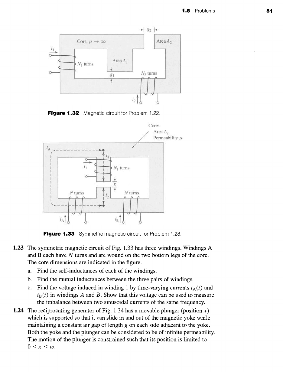
1.23 The symmetric magnetic circuit of Fig. 1.33 has three windings. Windings A
and B each have N turns and are wound on the two bottom legs of the core.
The core dimensions are indicated in the figure.
a. Find the self-inductances of each of the windings.
b. Find the mutual inductances between the three pairs of windings.
c. Find the voltage induced in winding 1 by time-varying currents iA(t) and
iB (t) in windings A and B. Show that this voltage can be used to measure
the imbalance between two sinusoidal currents of the same frequency.
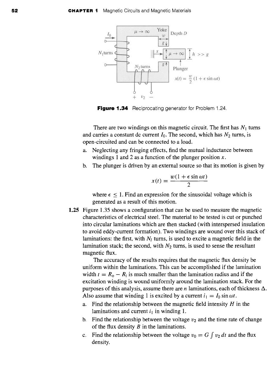
1.24 The reciprocating generator of Fig. 1.34 has a movable plunger (position x)
which is supported so that it can slide in and out of the magnetic yoke while
maintaining a constant air gap of length g on each side adjacent to the yoke.
Both the yoke and the plunger can be considered to be of infinite permeability.
The motion of the plunger is constrained such that its position is limited to
O<x<w.
52 CHAPTER 1 Magnetic Circuits and Magnetic Materials
Depth D
Nll
i i i ii i!iE iilii: i!!i!i!iiiiiiiiiii!iiiiiii!ii!!iiii:iil
t
Plunger
1/)
x(t)
= ~ (1 + E sin
cot)
-Jr- V2
Figure
1.34 Reciprocating generator for Problem 1.24.
There are two windings on this magnetic circuit. The first has N1 turns
and carries a constant dc current I0. The second, which has N2 turns, is
open-circuited and can be connected to a load.
a. Neglecting any fringing effects, find the mutual inductance between
windings 1 and 2 as a function of the plunger position x.
b. The plunger is driven by an external source so that its motion is given by
x(t) -
w (1 + E sin
cot)
where e < 1. Find an expression for the sinusoidal voltage which is
generated as a result of this motion.
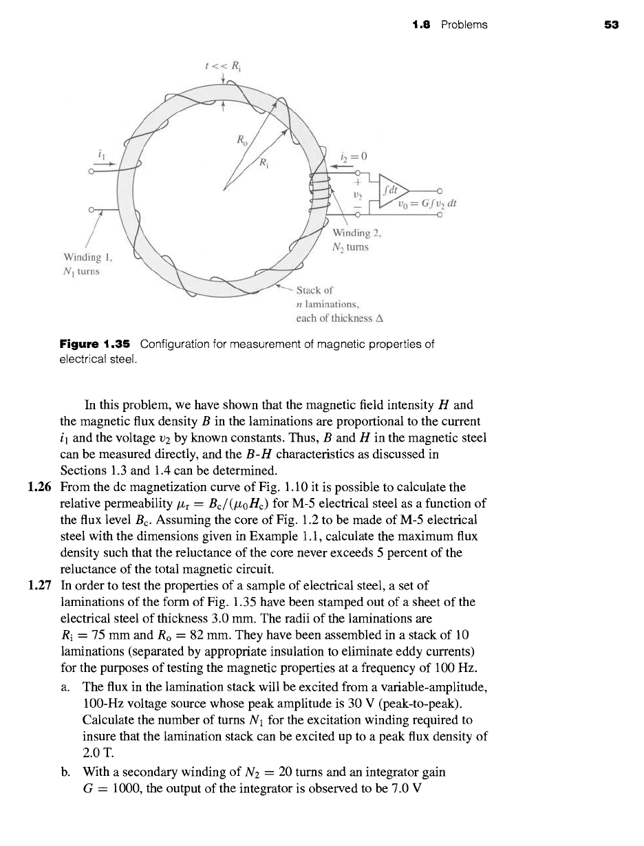
1.25 Figure 1.35 shows a configuration that can be used to measure the magnetic
characteristics of electrical steel. The material to be tested is cut or punched
into circular laminations which are then stacked (with interspersed insulation
to avoid eddy-current formation). Two windings are wound over this stack of
laminations: the first, with Nt turns, is used to excite a magnetic field in the
lamination stack; the second, with Ne turns, is used to sense the resultant
magnetic flux.
The accuracy of the results requires that the magnetic flux density be
uniform within the laminations. This can be accomplished if the lamination
width t = Ro - Ri is much smaller than the lamination radius and if the
excitation winding is wound uniformly around the lamination stack. For the
purposes of this analysis, assume there are n laminations, each of thickness A.
Also assume that winding 1 is excited by a current i l = I0 sin
wt.
a. Find the relationship between the magnetic field intensity H in the
laminations and current i l in winding 1.
b. Find the relationship between the voltage ve and the time rate of change
of the flux density B in the laminations.
c. Find the relationship between the voltage
vo = G f v2 dt
and the flux
density.
1.8 Problems
53
t<< R i
Ro
i2=0
v 0 = Gfv 2 dt
0
Winding 1,
N 1 turns
Winding 2,
N 2 turns
Stack of
n laminations,
each of thickness A
Figure
1.35 Configuration for measurement of magnetic properties of
electrical steel.
In this problem, we have shown that the magnetic field intensity H and
the magnetic flux density B in the laminations are proportional to the current
il and the voltage v2 by known constants. Thus, B and H in the magnetic steel
can be measured directly, and the
B-H
characteristics as discussed in
Sections 1.3 and 1.4 can be determined.
1.26 From the dc magnetization curve of Fig. 1.10 it is possible to calculate the
relative permeability/Zr =
Be/(/~0Hc)
for M-5 electrical steel as a function of
the flux level Bc. Assuming the core of Fig. 1.2 to be made of M-5 electrical
steel with the dimensions given in Example 1.1, calculate the maximum flux
density such that the reluctance of the core never exceeds 5 percent of the
reluctance of the total magnetic circuit.
1.27 In order to test the properties of a sample of electrical steel, a set of
laminations of the form of Fig. 1.35 have been stamped out of a sheet of the
electrical steel of thickness 3.0 mm. The radii of the laminations are
Ri = 75 mm and Ro = 82 mm. They have been assembled in a stack of 10
laminations (separated by appropriate insulation to eliminate eddy currents)
for the purposes of testing the magnetic properties at a frequency of 100 Hz.
a. The flux in the lamination stack will be excited from a variable-amplitude,
100-Hz voltage source whose peak amplitude is 30 V (peak-to-peak).
Calculate the number of turns N1 for the excitation winding required to
insure that the lamination stack can be excited up to a peak flux density of
2.0T.
b. With a secondary winding of N2 = 20 turns and an integrator gain
G = 1000, the output of the integrator is observed to be 7.0 V
54 CHAPTER
1 Magnetic Circuits and Magnetic Materials
I 1
o_.L
¢
N 1 ¢
¢
o
~i!iii~iii~i~iiiii~i~i~ii!iiiii~iiiii~!~i~ii~ii~iii!!~i~i~!iiiii!!!iii!~ii~i~i~iiiiii~ii!i~i~iiiiiii!iiiiiii~!~iiiiiiiiiiiiiiiiii~iiB~i~ii~ii~iiiii~i!iii~iiiii~!iii~i!ii~!iiii~i~iiiii!i!i!i~i~i
---o
)
O
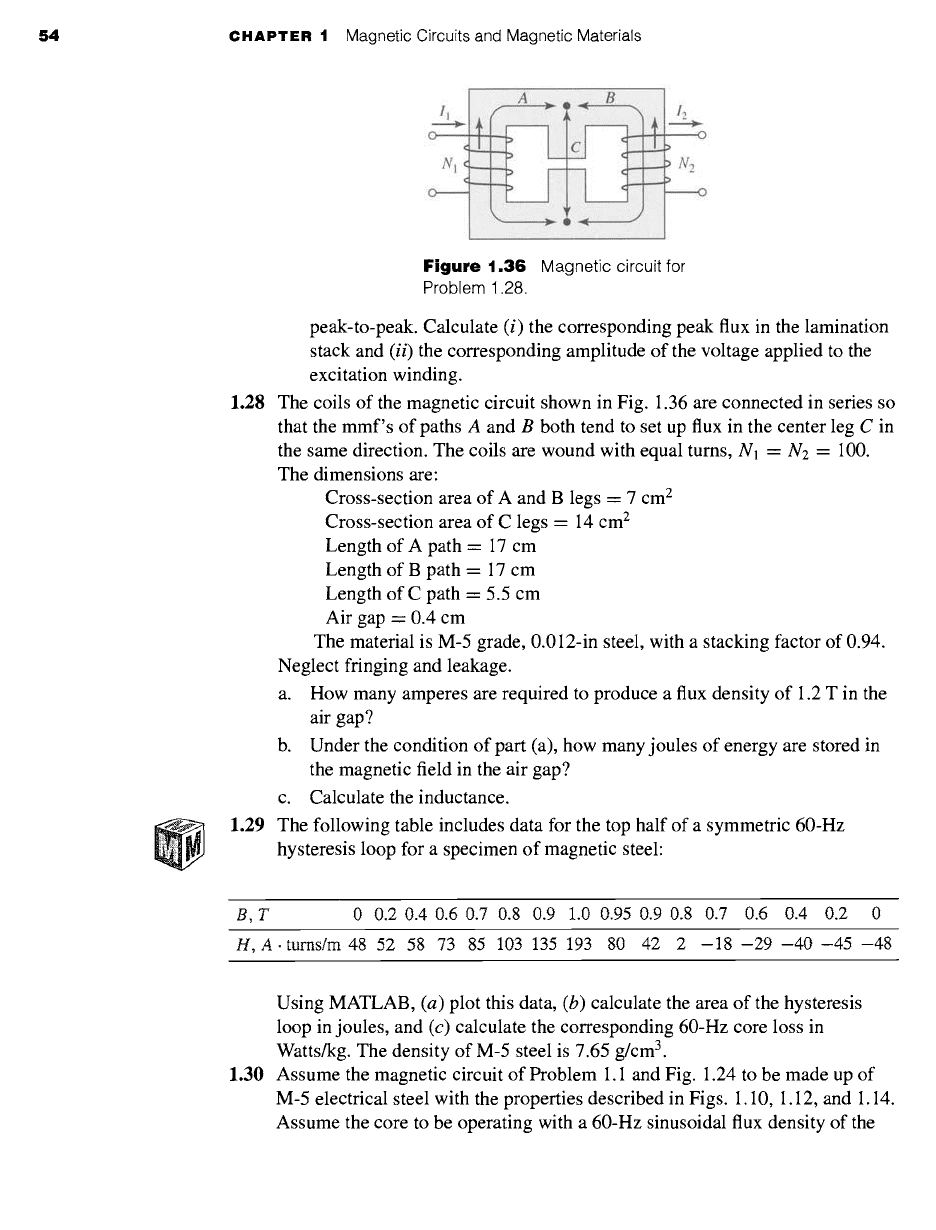
Figure 1.36
Magnetic circuit for
Problem 1.28.
peak-to-peak. Calculate (i) the corresponding peak flux in the lamination
stack and
(ii)
the corresponding amplitude of the voltage applied to the
excitation winding.
1.28 The coils of the magnetic circuit shown in Fig. 1.36 are connected in series so
that the mmf's of paths A and B both tend to set up flux in the center leg C in
the same direction. The coils are wound with equal turns, Nl = N2 = 100.
The dimensions are:
Cross-section area of A and B legs = 7 cm 2
Cross-section area of C legs = 14 cm 2
Length of A path = 17 cm
Length of B path = 17 cm
Length of C path = 5.5 cm
Air gap = 0.4 cm
The material is M-5 grade, 0.012-in steel, with a stacking factor of 0.94.
Neglect fringing and leakage.
a. How many amperes are required to produce a flux density of 1.2 T in the
air gap?
b. Under the condition of part (a), how many joules of energy are stored in
the magnetic field in the air gap?
c. Calculate the inductance.
1.29 The following table includes data for the top half of a symmetric 60-Hz
hysteresis loop for a specimen of magnetic steel:
B,T 0 0.2 0.4 0.6 0.7 0.8 0.9 1.0 0.95 0.9 0.8 0.7 0.6 0.4 0.2 0
H,A.turns/m
48 52 58 73 85 103 135 193 80 42 2 -18-29-40-45-48
Using MATLAB, (a) plot this data, (b) calculate the area of the hysteresis
loop in joules, and (c) calculate the corresponding 60-Hz core loss in
Watts/kg. The density of M-5 steel is 7.65 g/cm 3.
1.30 Assume the magnetic circuit of Problem 1.1 and Fig. 1.24 to be made up of
M-5 electrical steel with the properties described in Figs. 1.10, 1.12, and 1.14.
Assume the core to be operating with a 60-Hz sinusoidal flux density of the
1.8 Problems 55
rms flux density of 1.1 T. Neglect the winding resistance and leakage
inductance. Find the winding voltage, rms winding current, and core loss for
this operating condition. The density of M-5 steel is 7.65 g/cm 3.
1.31 Repeat Example 1.8 under the assumption that all the core dimensions are
doubled.
1.32 Using the magnetization characteristics for samarium cobalt given in
Fig. 1.19, find the point of maximum energy product and the corresponding
flux density and magnetic field intensity. Using these values, repeat
Example 1.10 with the Alnico 5 magnet replaced by a samarium-cobalt
magnet. By what factor does this reduce the magnet volume required to
achieve the desired air-gap flux density?
1.33 Using the magnetization characteristics for neodymium-iron-boron given in
Fig. 1.19, find the point of maximum-energy product and the corresponding
flux density and magnetic field intensity. Using these values, repeat
Example 1.10 with the Alnico 5 magnet replaced by a neodymium-iron-boron
magnet. By what factor does this reduce the magnet volume required to
achieve the desired air-gap flux density?
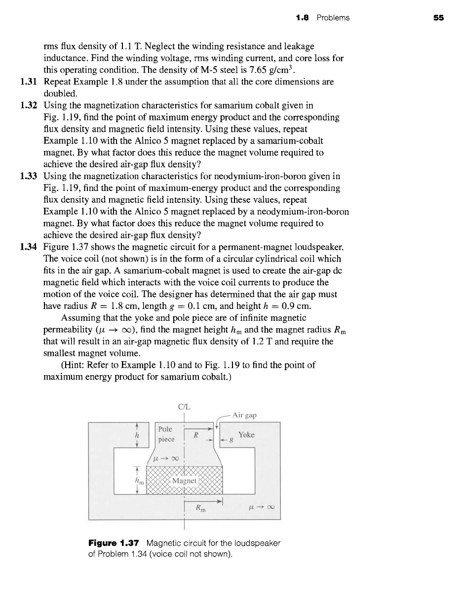
1.34 Figure 1.37 shows the magnetic circuit for a permanent-magnet loudspeaker.
The voice coil (not shown) is in the form of a circular cylindrical coil which
fits in the air gap. A samarium-cobalt magnet is used to create the air-gap dc
magnetic field which interacts with the voice coil currents to produce the
motion of the voice coil. The designer has determined that the air gap must
have radius R = 1.8 cm, length g = 0.1 cm, and height h = 0.9 cm.
Assuming that the yoke and pole piece are of infinite magnetic
permeability (/z --+ oe), find the magnet height hm and the magnet radius Rm
that will result in an air-gap magnetic flux density of 1.2 T and require the
smallest magnet volume.
(Hint: Refer to Example 1.10 and to Fig. 1.19 to find the point of
maximum energy product for samarium cobalt.)
C/L
Figure 1.37
Magnetic circuit for the loudspeaker
of Problem 1.34 (voice coil not shown).