Fitzgerald A.E. Electric Machinery
Подождите немного. Документ загружается.

6 CHAPTER 1 Magnetic Circuits and Magnetic Materials
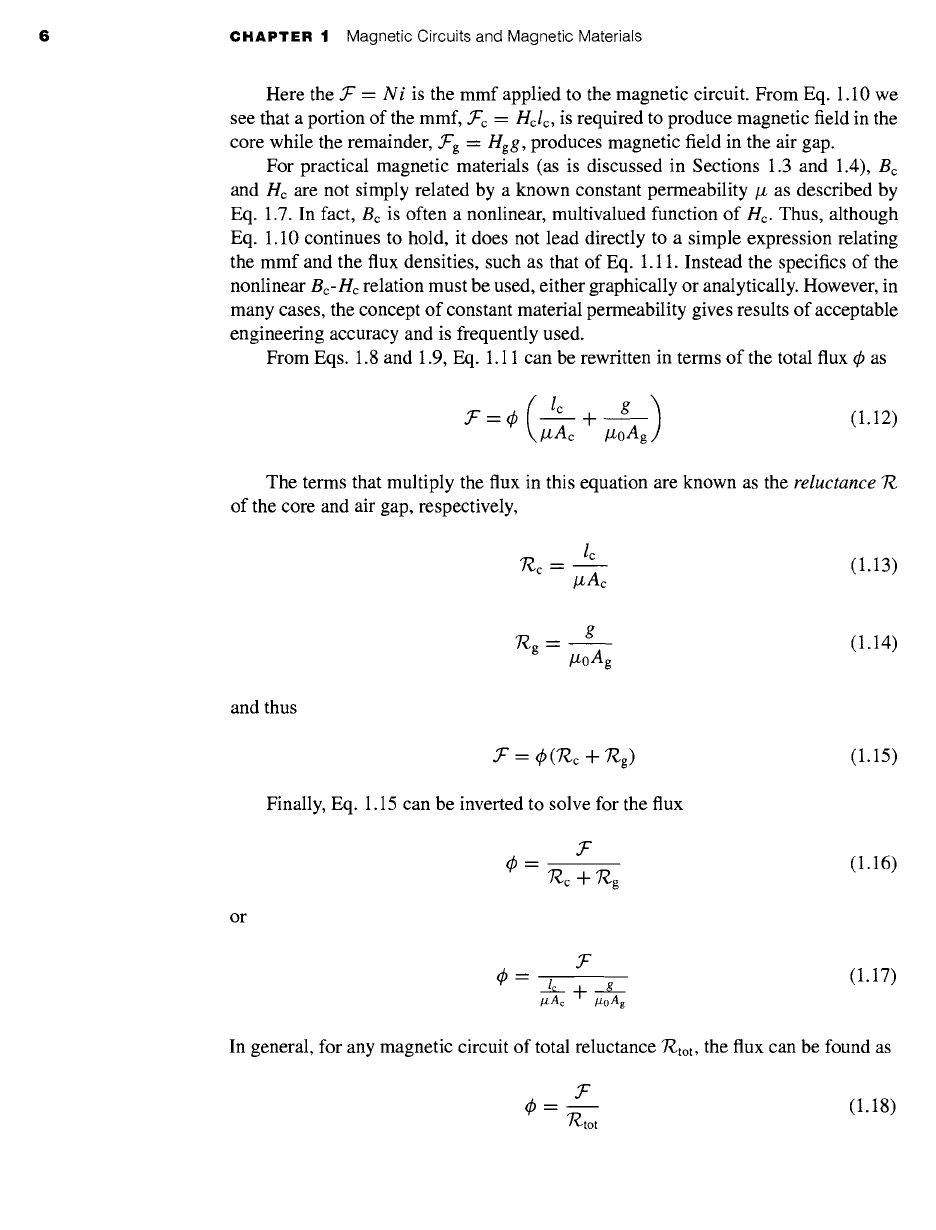
Here the ~" = Ni is the mmf applied to the magnetic circuit. From Eq. 1.10 we
see that a portion of the mmf, .Tc = Hclc, is required to produce magnetic field in the
core while the remainder, fg = Hgg, produces magnetic field in the air gap.
For practical magnetic materials (as is discussed in Sections 1.3 and 1.4), Bc
and Hc are not simply related by a known constant permeability/z as described by
Eq. 1.7. In fact, Bc is often a nonlinear, multivalued function of Hc. Thus, although
Eq. 1.10 continues to hold, it does not lead directly to a simple expression relating
the mmf and the flux densities, such as that of Eq. 1.11. Instead the specifics of the
nonlinear Bc-He relation must be used, either graphically or analytically. However, in
many cases, the concept of constant material permeability gives results of acceptable
engineering accuracy and is frequently used.
From Eqs. 1.8 and 1.9, Eq. 1.11 can be rewritten in terms of the total flux ~b as
lc g )
"f'=q~ ~ + /~oAg
(1.12)
The terms that multiply the flux in this equation are known as the reluctance T~
of the core and air gap, respectively,
lC
~c -- (1.13)
#Ac
g
J'~g --
(1.14)
/zoAg
and thus
~" = q~(7~c + ~g) (1.15)
Finally, Eq. 1.15 can be inverted to solve for the flux
(1.16)
or
/zAc #0Ag
(1.17)
In general, for any magnetic circuit of total reluctance
7"~tot,
the flux can be found as
y-
q~ -- (1.18)
7~tot
1,1 Introduction to Magnetic Circuits 7
+
v(
)
I 4,
gl
+
y.
R2
V Y"
I = (R 1 + R2 ) ~b = (7~c + 7~g)
(a) (b)
'T•.
c
7"¢.g
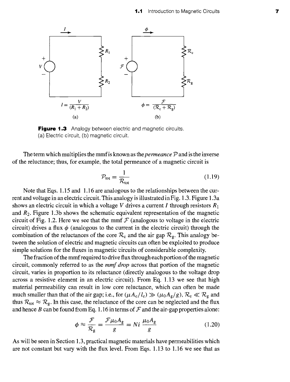
Figure
1.3 Analogy between electric and magnetic circuits.
(a) Electric circuit, (b) magnetic circuit.
The term which multiplies the mmfis known as thepermeance
7 -9
and is the inverse
of the reluctance; thus, for example, the total permeance of a magnetic circuit is
1
~tot = 7-~tot (1.19)
Note that Eqs. 1.15 and 1.16 are analogous to the relationships between the cur-
rent and voltage in an electric circuit. This analogy is illustrated in Fig. 1.3. Figure 1.3a
shows an electric circuit in which a voltage V drives a current I through resistors R1
and R2. Figure 1.3b shows the schematic equivalent representation of the magnetic
circuit of Fig. 1.2. Here we see that the mmf ~ (analogous to voltage in the electric
circuit) drives a flux ¢ (analogous to the current in the electric circuit) through the
combination of the reluctances of the core 7~c and the air gap ~g. This analogy be-
tween the solution of electric and magnetic circuits can often be exploited to produce
simple solutions for the fluxes in magnetic °circuits of considerable complexity.
The fraction of the mmfrequired to drive flux through each portion of the magnetic
circuit, commonly referred to as the
mmf drop
across that portion of the magnetic
circuit, varies in proportion to its reluctance (directly analogous to the voltage drop
across a resistive element in an electric circuit). From Eq. 1.13 we see that high
material permeability can result in low core reluctance, which can often be made
much smaller than that of the air gap; i.e., for
(IzAc/lc)
>>
(lzoAg/g),
"R.c <<
~'P~g
and
thus
"~-tot ~ ']'~g.
In this case, the reluctance of the core can be neglected and the flux
and hence B can be found from Eq. 1.16 in terms of f and the air-gap properties alone:
.T" .T'/z0Ag /z0Ag
ck ~ ~ = = N i
(1.20)
T~g g
g
As will be seen in Section 1.3, practical magnetic materials have permeabilities which
are not constant but vary with the flux level. From Eqs. 1.13 to 1.16 we see that as
8 CHAPTER 1 Magnetic Circuits and Magnetic Materials
Fringing
fields
Air gap
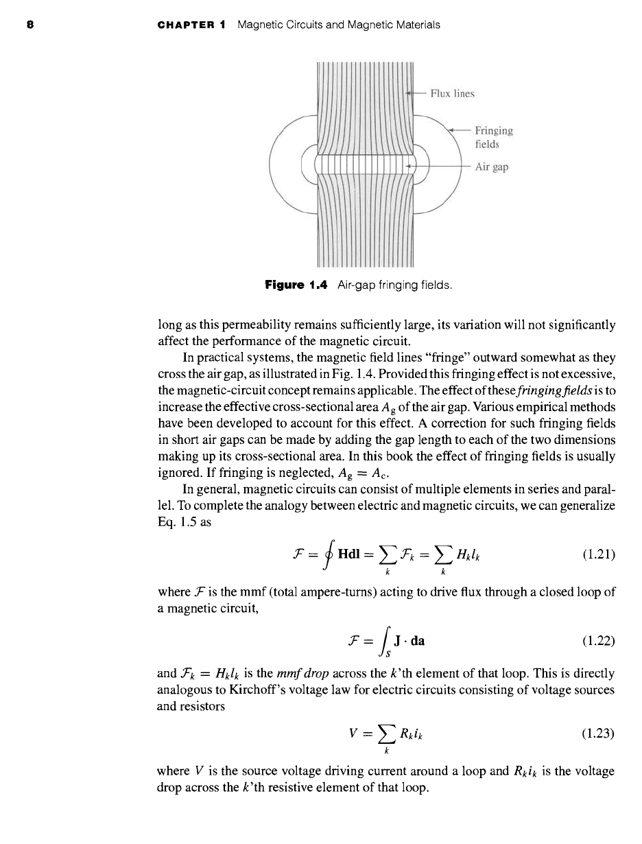
Figure 1.4
Air-gap fringing fields.
long as this permeability remains sufficiently large, its variation will not significantly
affect the performance of the magnetic circuit.
In practical systems, the magnetic field lines "fringe" outward somewhat as they
cross the air gap, as illustrated in Fig. 1.4. Provided this fringing effect is not excessive,
the magnetic-circuit concept remains applicable. The effect of
thesefringingfields
is to
increase the effective cross-sectional area Ag of the air gap. Various empirical methods
have been developed to account for this effect. A correction for such fringing fields
in short air gaps can be made by adding the gap length to each of the two dimensions
making up its cross-sectional area. In this book the effect of fringing fields is usually
ignored. If fringing is neglected, Ag = Ac.
In general, magnetic circuits can consist of multiple elements in series and paral-
lel. To complete the analogy between electric and magnetic circuits, we can generalize
Eq. 1.5 as
.T" = f Hdl = Z )ok = Z
Hklk
(1.21)
k k
where .T" is the mmf (total ampere-turns) acting to drive flux through a closed loop of
a magnetic circuit,
= Jl J" da (1.22)
and 3ok =
Hklk
is the
mmfdrop
across the k'th element of that loop. This is directly
analogous to Kirchoff's voltage law for electric circuits consisting of voltage sources
and resistors
= Z Rkik (
V
1.23)
k
where V is the source voltage driving current around a loop and
Rkik
is the voltage
drop across the k'th resistive element of that loop.
1.1 Introduction to Magnetic Circuits 9
Similarly, the analogy to Kirchoff's current law
Z in = 0 (1.24)
n
which says that the sum of currents into a node in an electric circuit equals zero is
Z ~n -- 0 (1.25)
n
which states that the sum of the flux into a node in a magnetic circuit is zero.
We have now described the basic principles for reducing a magneto-quasistatic
field problem with simple geometry to a
magnetic circuit model.
Our limited pur-
pose in this section is to introduce some of the concepts and terminology used by
engineers in solving practical design problems. We must emphasize that this type of
thinking depends quite heavily on engineering judgment and intuition. For example,
we have tacitly assumed that the permeability of the "iron" parts of the magnetic
circuit is a constant known quantity, although this is not true in general (see Sec-
tion 1.3), and that the magnetic field is confined soley to the core and its air gaps.
Although this is a good assumption in many situations, it is also true that the wind-
ing currents produce magnetic fields outside the core. As we shall see, when two
or more windings are placed on a magnetic circuit, as happens in the case of both
transformers and rotating machines, these fields outside the core, which are referred
to as
leakage fields,
cannot be ignored and significantly affect the performance of the
device.
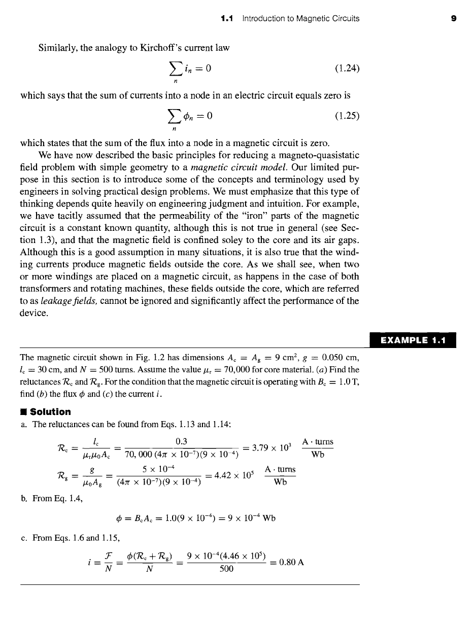
The magnetic circuit shown in Fig. 1.2 has dimensions Ac = Ag = 9 cm 2, g = 0.050 cm,
lc = 30 cm, and N = 500 tums. Assume the value/J.r
= 70,000
for core material. (a) Find the
reluctances 7-¢.c and 7"¢.g. For the condition that the magnetic circuit is operating with Bc = 1.0 T,
find (b) the flux 4) and (c) the current i.
II
Solution
a. The reluctances can be found from Eqs. 1.13 and 1.14:
7¢.c = lc _- 0.3 --- 3.79 x 10³
/zr/z0Ac 70,000 (4zr x 10-7)(9 x 10 -4)
7"¢.g = g = 5 × 10 -4
/x0Ag (47r x 10-7)(9 x 10 -4) = 4.42 X 10⁵ A.wbtUms
b. From Eq. 1.4,
A. turns
Wb
= BcAc
= 1.0(9 x 10 -4) = 9 × 10⁻⁴ Wb
c. From Eqs. 1.6 and 1.15,
N
(])(T~ c -~- "/~g)
9 x 10⁻⁴(4.46 x 10⁵)
N 500
= 0.80A
EXAMPLE 1.1
10 CHAPTER 1 Magnetic Circuits and Magnetic Materials
)ractice Problem 1.'
Find the flux 4) and current for Example 1.1 if (a) the number of turns is doubled to N = 1000
turns while the circuit dimensions remain the same and (b) if the number of turns is equal to
N = 500 and the gap is reduced to 0.040 cm.
Solution
a. ~b = 9 x 10
-4
Wb and i = 0.40 A
b. ¢=9x 10 -4Wbandi=0.64A
!XAMPLE 1 :
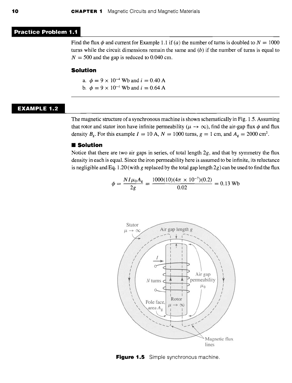
The magnetic structure of a synchronous machine is shown schematically in Fig. 1.5. Assuming
that rotor and stator iron have infinite permeability (# --+ c~), find the air-gap flux ~b and flux
density Bg. For this example I = 10 A, N = 1000 turns, g = 1 cm, and Ag = 2000 cm 2.
1
Solution
Notice that there are two air gaps in series, of total length 2g, and that by symmetry the flux
density in each is equal. Since the iron permeability here is assumed to be infinite, its reluctance
is negligible and Eq. 1.20 (with g replaced by the total gap length 2g) can be used to find the flux
NltxoAg
1000(10)(4Jr
x
10-7)(0.2)
= = = 0.13 Wb
2g 0.02
Stator
/z --+ o~
/,L:: :::::::A~ gap length g
::: :::::
.............. :: ::: ....
j L:i:
I I
c" ....... Air gap
N turns ¢ ......... permeability
~ I I No
I
Pole face, Rotor i
~S.,r,." t...
1" i
Magnetic flux
lines
Figure
1.5 Simple synchronous machine.
1.2 Flux Linkage, Inductance, and Energy 11
and
0.13
Bg =
A---~ = 0.2
= 0.65 T
~ractice Problem 1.:
For the magnetic structure of Fig. 1.5 with the dimensions as given in Example 1.2, the air-gap
flux density is observed to be Bg = 0.9 T. Find the air-gap flux ~b and, for a coil of N -- 500
turns, the current required to produce this level of air-gap flux.
Solution
4) = 0.18 Wb and i = 28.6 A.
1.2 FLUX LINKAGE, INDUCTANCE,
AND ENERGY
When a magnetic field varies with time, an electric field is produced in space as
determined by
Faraday's law:
g. Os - -~ B. da (1.26)
Equation 1.26 states that the line integral of the
electric field intensity
E around a
closed contour C is equal to the time rate of change of the magnetic flux linking (i.e.
passing through) that contour. In magnetic structures with windings of high electrical
conductivity, such as in Fig. 1.2, it can be shown that the E field in the wire is
extremely small and can be neglected, so that the left-hand side of Eq. 1.26 reduces to
the negative of the
induced voltage 4 e
at the winding terminals. In addition, the flux
on the right-hand side of Eq. 1.26 is dominated by the core flux 4~. Since the winding
(and hence the contour C) links the core flux N times, Eq. 1.26 reduces to
d~0 dl.
e = N dt = d---t- (1.27)
where ~. is the
flux linkage
of the winding and is defined as
= Nq9 (1.28)
Flux linkage is measured in units of webers (or equivalently weber-turns). The symbol
q9 is used to indicate the instantaneous value of a time-varying flux.
In general the flux linkage of a coil is equal to the surface integral of the normal
component of the magnetic flux density integrated over any surface spanned by that
coil. Note that the direction of the induced voltage e is defined by Eq. 1.26 so that if
4 The term
electromotive force
(emf) is often used instead of
induced voltage
to represent that component
of voltage due to a time-varying flux linkage.
12 CHAPTER 1 Magnetic Circuits and Magnetic Materials
the winding terminals were short-circuited, a current would flow in such a direction
as to oppose the change of flux linkage.
For a magnetic circuit composed of magnetic material of constant magnetic
permeability or which includes a dominating air gap, the relationship between q~ and
i will be linear and we can define the
inductance L
as
L -- - (1.29)
i
Substitution of Eqs. 1.5, 1.18 and 1.28 into Eq. 1.29 gives
N 2
L = (1.30)
T~tot
From which we see that the inductance of a winding in a magnetic circuit is propor-
tional to the square of the turns and inversely proportional to the reluctance of the
magnetic circuit associated with that winding.
For example, from Eq. 1.20, under the assumption that the reluctance of the core
is negligible as compared to that of the air gap, the inductance of the winding in
Fig. 1.2 is equal to
N 2 N2/zoAg
L -- = (1.31)
(g/lzoag) g
Inductance is measured in
henrys
(H) or
weber-turns per ampere.
Equation 1.31
shows the dimensional form of expressions for inductance; inductance is proportional
to the square of the number of turns, to a magnetic permeability, and to a cross-
sectional area and is inversely proportional to a length. It must be emphasized that,
strictly speaking, the concept of inductance requires a linear relationship between
flux and mmf. Thus, it cannot be rigorously applied in situations where the nonlinear
characteristics of magnetic materials, as is discussed in Sections 1.3 and 1.4, dominate
the performance of the magnetic system. However, in many situations of practical
interest, the reluctance of the system is dominated by that of an air gap (which is of
course linear) and the nonlinear effects of the magnetic material can be ignored. In
other cases it may be perfectly acceptable to assume an average value of magnetic
permeability for the core material and to calculate a corresponding average inductance
which can be used for calculations of reasonable engineering accuracy. Example 1.3
illustrates the former situation and Example 1.4 the latter.
EXAMPLE 1.3
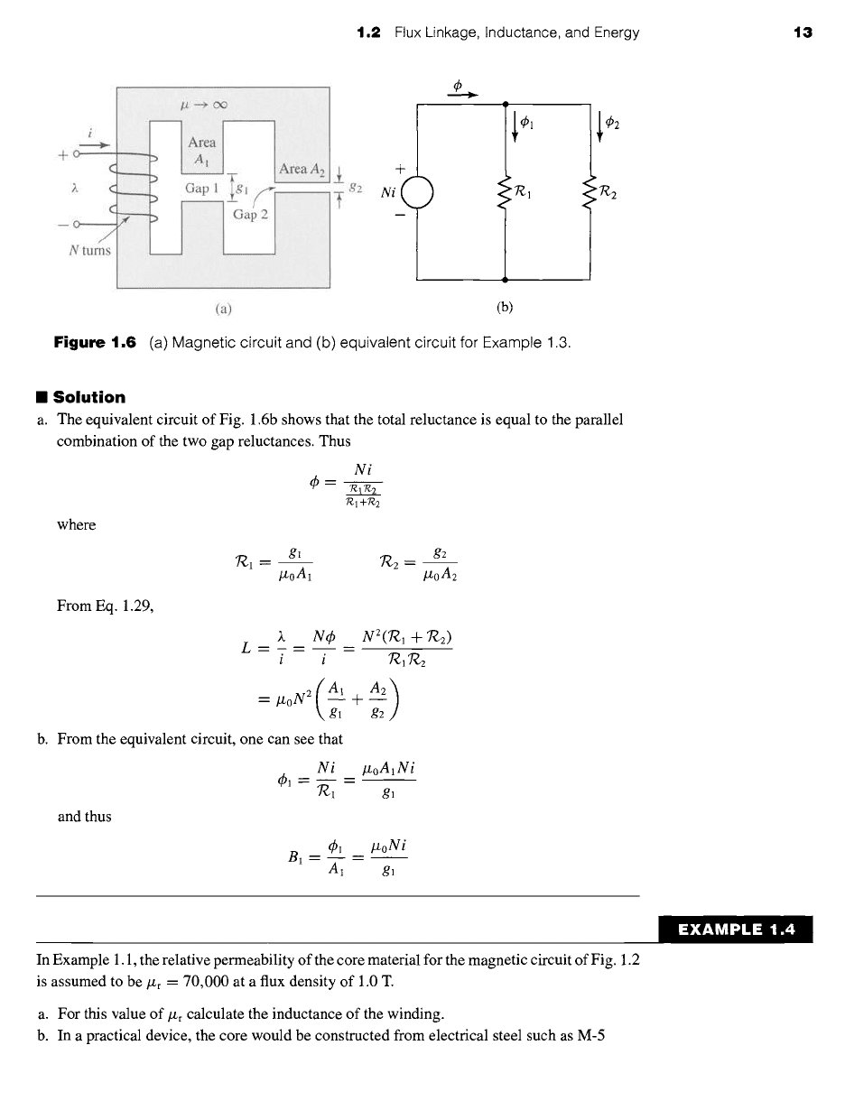
The magnetic circuit of Fig. 1.6a consists of an N-turn winding on a magnetic core of infinite
permeability with two parallel air gaps of lengths g~ and g2 and areas A~ and A2, respectively.
Find (a) the inductance of the winding and (b) the flux density Bl in gap 1 when the
winding is carrying a current i. Neglect fringing effects at the air gap.
1.2 Flux Linkage, Inductance, and Energy 13
-~ g2
N i+~
-f _
¢
~'1 'T~'2
(a) (b)
Figure
1.6 (a) Magnetic circuit and (b) equivalent circuit for Example 1.3.
II Solution
a. The equivalent circuit of Fig. 1.6b shows that the total reluctance is equal to the parallel
combination of the two gap reluctances. Thus
Ni
¢
~ 7-~17-~2
7?,. 1 +7"~ 2
where
g~
g2
/zoA1 /./,oA2
From Eq. 1.29,
)~ N¢
N2('~l + 'J~2)
L _~ ~ ~ _m
i i
7~]7~2
(A1 A_~2~ )
= lzoN z ~ +
gl
b. From the equivalent circuit, one can see that
Ni lzoA1Ni
1 ~ B
"~1 g l
and thus
¢1 lzoNi
B1--~--
A1
gl
In Example 1.1, the relative permeability of the core material for the magnetic circuit of Fig. 1.2
is assumed to be ~u~ r
--" 70,000
at a flux density of 1.0 T.
a. For this value of ]-£r calculate the inductance of the winding.
b. In a practical device, the core would be constructed from electrical steel such as M-5
EXAMPLE 1.4
14 CHAPTER 1 Magnetic Circuits and Magnetic Materials
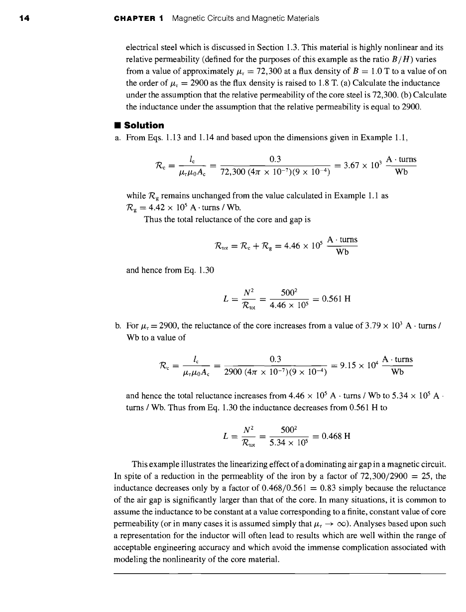
electrical steel which is discussed in Section 1.3. This material is highly nonlinear and its
relative permeability (defined for the purposes of this example as the ratio B/H) varies
from a value of approximately #r
---
72,300 at a flux density of B = 1.0 T to a value of on
the order of #r
"--
2900 as the flux density is raised to 1.8 T. (a) Calculate the inductance
under the assumption that the relative permeability of the core steel is 72,300. (b) Calculate
the inductance under the assumption that the relative permeability is equal to 2900.
II
Solution
a. From Eqs. 1.13 and 1.14 and based upon the dimensions given in Example 1.1,
7~c = lc _ _ 0.3 -- -- 3.67 x 10³ A. turns
/Zr/z0Ac 72,300 (4zr × 10-7)(9 × 10 -4) Wb
while Rg remains unchanged from the value calculated in Example 1.1 as
7~g = 4.42 x 10⁵ A. turns / Wb.
Thus the total reluctance of the core and gap is
7~tot = '~c + "~g = 4.46 x 10 s A. tums
Wb
and hence from Eq. 1.30
N 2 5002
L = = = 0.561 H
7"~,to t
4.46 x l0 s
b. For #r
~---
2900, the reluctance of the core increases from a value of 3.79 × 10³ A • turns /
Wb to a value of
lc 0.3 A. turns
~c = = = 9.15
x 10 4
/Zr#0Ac 2900 (4zr x 10-7)(9 x 10 -4) Wb
and hence the total reluctance increases from 4.46 x 10⁵ A • turns / Wb to 5.34 x 10⁵ A •
turns / Wb. Thus from Eq. 1.30 the inductance decreases from 0.561 H to
N 2 5002
L = = = 0.468 H
~tot 5.34 x 10 s
This example illustrates the linearizing effect of a dominating air gap in a magnetic circuit.
In spite of a reduction in the permeablity of the iron by a factor of 72,300/2900 = 25, the
inductance decreases only by a factor of 0.468/0.561 = 0.83 simply because the reluctance
of the air gap is significantly larger than that of the core. In many situations, it is common to
assume the inductance to be constant at a value corresponding to a finite, constant value of core
permeability (or in many cases it is assumed simply that/z r
~ (X)).
Analyses based upon such
a representation for the inductor will often lead to results which are well within the range of
acceptable engineering accuracy and which avoid the immense complication associated with
modeling the nonlinearity of the core material.
1.2 Flux Linkage, Inductance, and Energy 15
~ractice Problem 1.;
Repeat the inductance calculation of Example 1.4 for a relative permeability/L/, r
=
30,000.~
Solution
L = 0.554 H
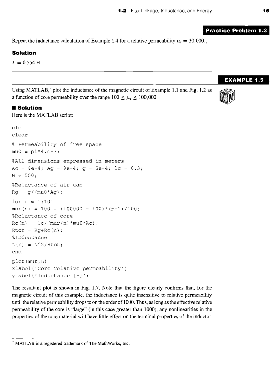
Using MATLAB, t plot the inductance of the magnetic circuit of Example 1.1 and Fig. 1.2 as
a
function of core permeability over the range
100 < Jt/,r _~ 100,000.
II Solution
Here is the MATLAB script:
clc
clear
% Permeability of free space
mu0 = pi*4.e-7;
%All dimensions expressed in meters
Ac = 9e-4; Ag = 9e-4; g = 5e-4; ic = 0.3;
N = 500 ;
%Reluctance of air gap
Rg = g/(mu0*Ag) ;
for n = i:i01
mur(n) = i00 + (i00000 - 100)*(n-l)/100;
%Reluctance of core
Rc(n) = ic/(mur(n)*mu0*ic) ;
Rtot = Rg+Rc(n) ;
%Inductance
L(n) = N^2/Rtot;
end
plot (tour, L)
xlabel('Core relative permeability')
ylabel('Inductance [H] ')
The resultant plot is shown in Fig. 1.7. Note that the figure clearly confirms that, for the
magnetic circuit of this example, the inductance is quite insensitive to relative permeability
until the relative permeability drops to on the order of 1000. Thus, as long as the effective relative
permeability of the core is "large" (in this case greater than 1000), any nonlinearities in the
properties of the core material will have little effect on the terminal properties of the inductor.
EXAMPLE 1.5
t MATLAB is a registered trademark of The MathWorks, Inc.