Fitzgerald A.E. Electric Machinery
Подождите немного. Документ загружается.

566 CHAPTER 11 Speed and Torque Control
Series
field
T "
--
Shunt
field
(a) (b)
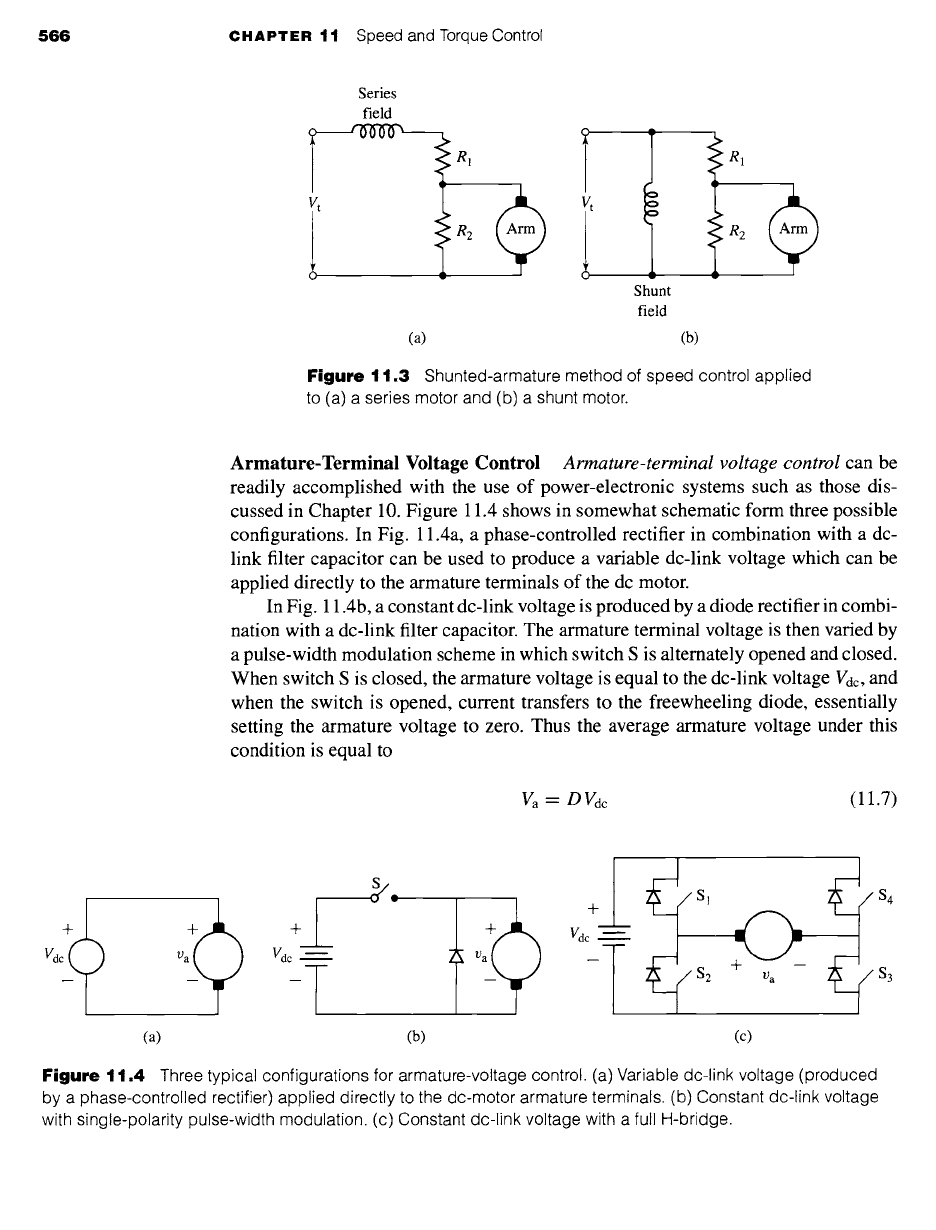
Figure
11.3 Shunted-armature method of speed control applied
to (a) a series motor and (b) a shunt motor.
Armature-Terminal Voltage Control
Armature-terminal voltage control
can be
readily accomplished with the use of power-electronic systems such as those dis-
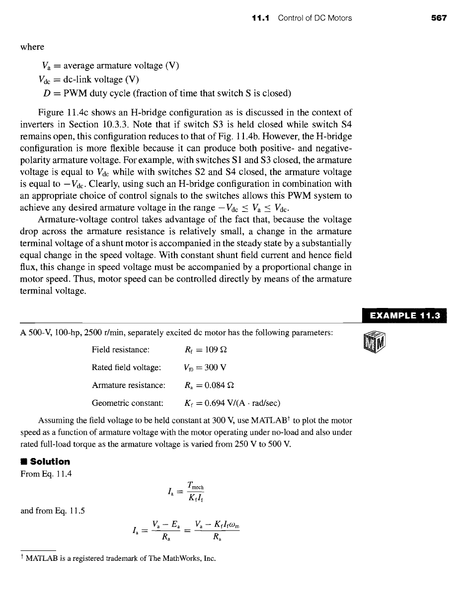
cussed in Chapter 10. Figure 11.4 shows in somewhat schematic form three possible
configurations. In Fig. 11.4a, a phase-controlled rectifier in combination with a dc-
link filter capacitor can be used to produce a variable dc-link voltage which can be
applied directly to the armature terminals of the dc motor.
In Fig. 11.4b, a constant dc-link voltage is produced by a diode rectifier in combi-
nation with a dc-link filter capacitor. The armature terminal voltage is then varied by
a pulse-width modulation scheme in which switch S is alternately opened and closed.
When switch S is closed, the armature voltage is equal to the dc-link voltage Vdc, and
when the switch is opened, current transfers to the freewheeling diode, essentially
setting the armature voltage to zero. Thus the average armature voltage under this
condition is equal to
Va = D Vdc
(11.7)
' 1
L ' +
+ + + + Vdc
I
r
(a)
(b)
(c)
Figure
11.4 Three typical configurations for armature-voltage control. (a) Variable dc-link voltage (produced
by a phase-controlled rectifier) applied directly to the dc-motor armature terminals. (b) Constant dc-link voltage
with single-polarity pulse-width modulation. (c) Constant dc-link voltage with a full H-bridge.
11.1 Control of DC Motors 567
where
Va = average armature voltage (V)
Vdc = dc-link voltage (V)
D = PWM duty cycle (fraction of time that switch S is closed)
Figure 11.4c shows an H-bridge configuration as is discussed in the context of
inverters in Section 10.3.3. Note that if switch $3 is held closed while switch $4
remains open, this configuration reduces to that of Fig. 11.4b. However, the H-bridge
configuration is more flexible because it can produce both positive- and negative-
polarity armature voltage. For example, with switches S 1 and $3 closed, the armature
voltage is equal to V~c while with switches $2 and $4 closed, the armature voltage
is equal to -Vdc. Clearly, using such an H-bridge configuration in combination with
an appropriate choice of control signals to the switches allows this PWM system to
achieve any desired armature voltage in the range -V~c < Va < V~c.
Armature-voltage control takes advantage of the fact that, because the voltage
drop across the armature resistance is relatively small, a change in the armature
terminal voltage of a shunt motor is accompanied in the steady state by a substantially
equal change in the speed voltage. With constant shunt field current and hence field
flux, this change in speed voltage must be accompanied by a proportional change in
motor speed. Thus, motor speed can be controlled directly by means of the armature
terminal voltage.
~: EX A MPL E :~ 1 ~ 1: .3
A 500-V, 100-hp, 2500 r/min, separately excited dc motor has the following parameters:
Field resistance:
Re =
109
Rated field voltage: Vf0 = 300 V
Armature resistance:
Ra =
0.084 f2
Geometric constant: Kf = 0.694 V/(A • rad/sec)
Assuming the field voltage to be held constant at 300 V, use MATLAB t to plot the motor
speed as a function of armature voltage with the motor operating under no-load and also under
rated full-load torque as the armature voltage is varied from 250 V to 500 V.
II
Solution
From Eq. 11.4
and from Eq. 11.5
Tmech
Ia=
Kflf
L
Va - Ea
Ra
Va-
Kf/fO.)m
Ra
t MATLAB is a registered trademark of The MathWorks, Inc.
Hence we can solve for O)m
09 m
Kflf
( mec "a)
(30)
n
=
--
O) m
7/"
and the speed in r/min as
Finally, the field current is
Vf
Re
300
109
co
= 2.75 A
and the rated full-load torque is given by
Prated
100
x
746
Trate d = -- --
285 N • m
(O)m)rated 2500 X (~00)
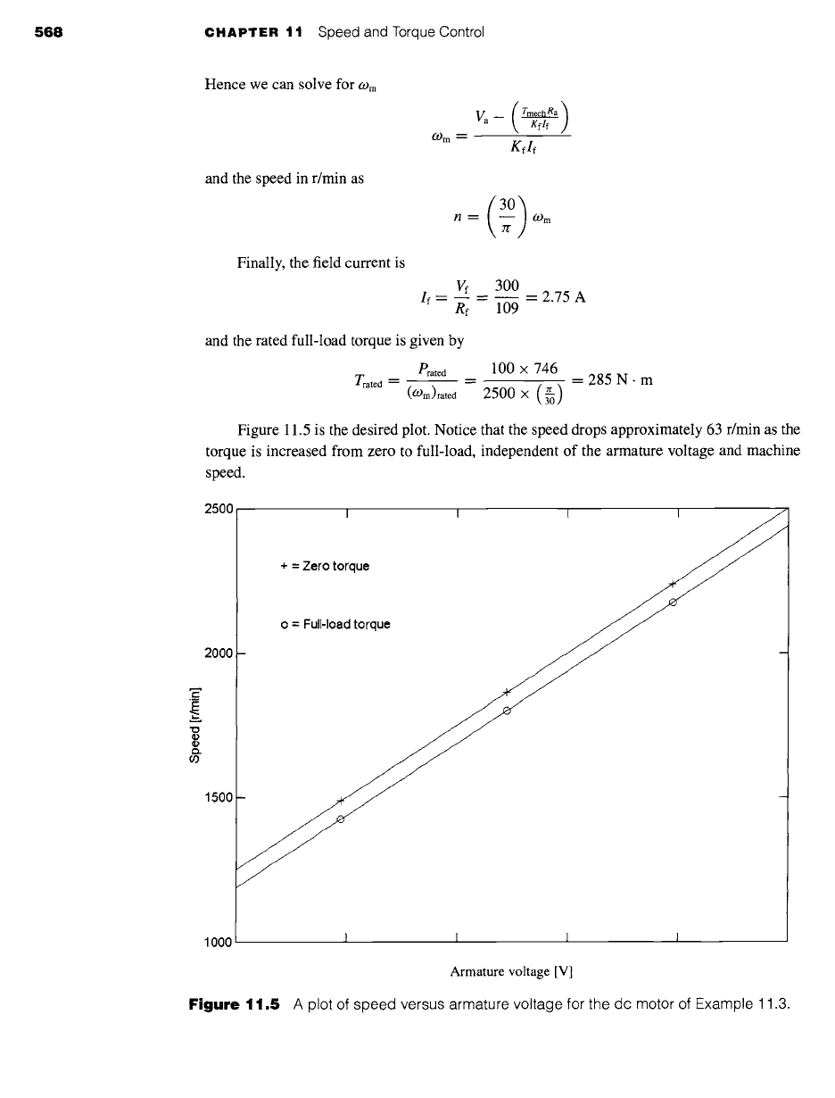
Figure 11.5 is the desired plot. Notice that the speed drops approximately 63 r/min as the
torque is increased from zero to full-load, independent of the armature voltage and machine
speed.
2500
I I I I 7~
+ = Zero torque
--- _
2000
1500
1000
568
CHAPTER 11 Speed and Torque Control
I I I I
Armature voltage [V]
Figure
11.5 A plot of speed versus armature voltage for the dc motor of Example 11.3.
t t.t Control of DC Motors 569
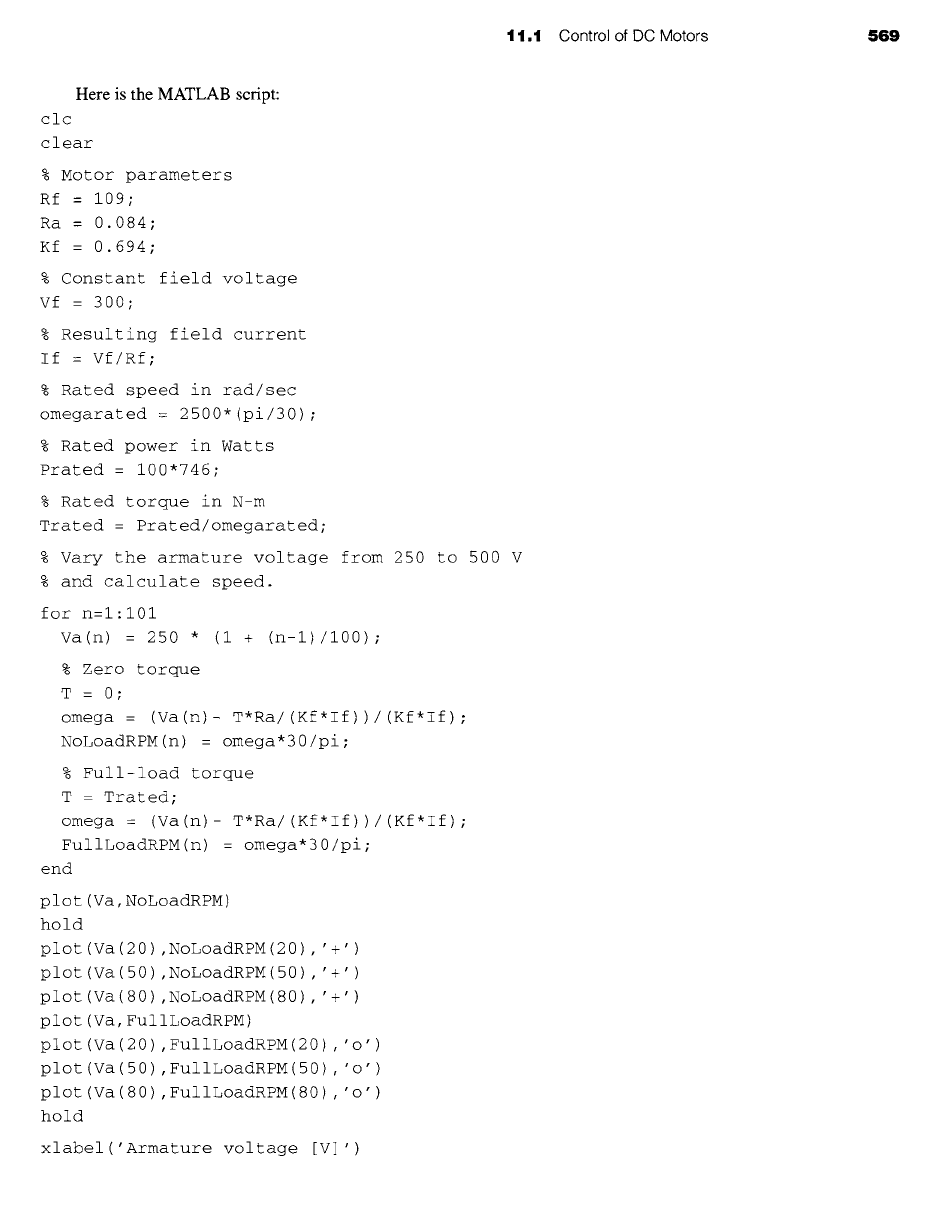
Here is the MATLAB script:
clc
clear
% Motor parameters
Rf = 109;
Ra = 0.084;
Kf = 0.694;
% Constant field voltage
Vf = 3OO ;
% Resulting field current
If = Vf/Rf;
% Rated speed in rad/sec
omegarated : 2500"(pi/30) ;
% Rated power in Watts
Prated- 100"746;
% Rated torque in N-m
Trated = Prated/omegarated;
% Vary the armature voltage from 250 to 500 V
% and calculate speed.
for n=l:101
Va(n) = 250 * (i + (n-l)/i00) ;
% Zero torque
T = 0;
omega = (Va(n)- T*Ra/ (Kf*If))/(Kf*If) ;
NoLoadRPM(n) = omega*30/pi;
% Full-load torque
T - Trated;
omega : (Va(n)- T*Ra/ (Kf*If))/(Kf*If) ;
FullLoadRPM(n) = omega*30/pi;
end
plot (Va, NoLoadRPM)
hold
plot(Va(20) ,NoLoadRPM(20) , '+')
plot (Va (50) , NoLoadRPM (50) , ' +' )
plot (Va (80) ,NoLoadRPM (80) , ' +' )
plot (Va, FulILoadRPM)
plot (Va (20) ,FulILoadRPM(20) , 'o')
plot (Va (50) , FulILoadRPM (50) , ' o' )
plot (Va (80) , FulILoadRPM (80) , ' o' )
hold
xlabel('Armature voltage [V] ')
570 CHAPTER 11 Speed and Torque Control
ylabel('Speed [r/min]
')
text(270,2300,'+ : Zero torque')
text(270,2100,'o = Full-load torque')
Calculate the change in armature voltage required to maintain the motor of Example 11.3 at a
speed of 2000 r/min as the load is changed from zero to full-load torque.
Solution
12.5 V
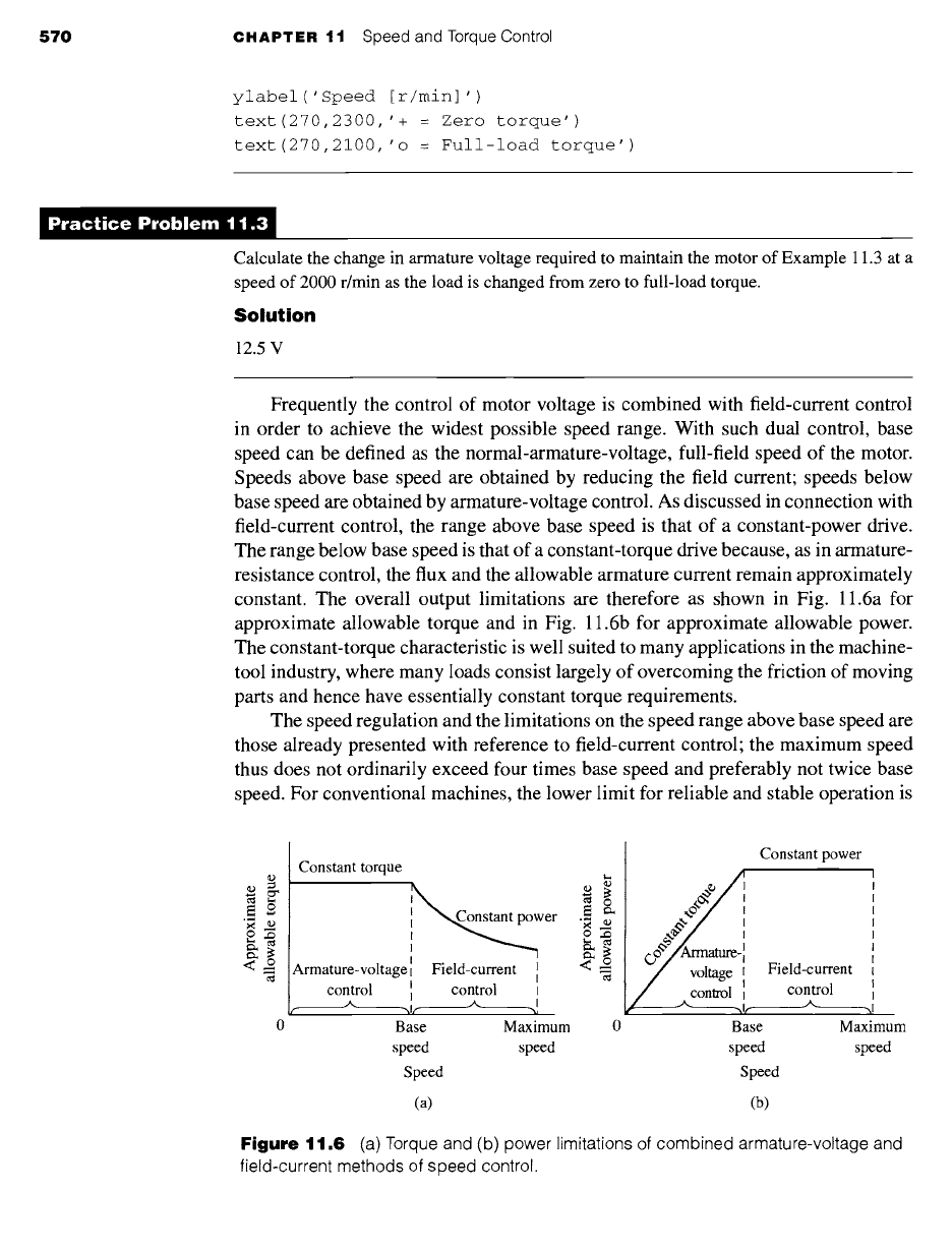
Frequently the control of motor voltage is combined with field-current control
in order to achieve the widest possible speed range. With such dual control, base
speed can be defined as the normal-armature-voltage, full-field speed of the motor.
Speeds above base speed are obtained by reducing the field current; speeds below
base speed are obtained by armature-voltage control. As discussed in connection with
field-current control, the range above base speed is that of a constant-power drive.
The range below base speed is that of a constant-torque drive because, as in armature-
resistance control, the flux and the allowable armature current remain approximately
constant. The overall output limitations are therefore as shown in Fig. 11.6a for
approximate allowable torque and in Fig. 11.6b for approximate allowable power.
The constant-torque characteristic is well suited to many applications in the machine-
tool industry, where many loads consist largely of overcoming the friction of moving
parts and hence have essentially constant torque requirements.
The speed regulation and the limitations on the speed range above base speed are
those already presented with reference to field-current control; the maximum speed
thus does not ordinarily exceed four times base speed and preferably not twice base
speed. For conventional machines, the lower limit for reliable and stable operation is
(D
<--
Constant torque
<~
wer
I
Armature-voltage Field-current I
control control I
I
-hit'- ..M ~l
Base Maximum
speed speed
Speed
0 0
Constant power
o/I
#*"/
I
eo°/A,=a~-I
voltage!
Base
speed
Speed
(a) (b)
Field-current
control
J'-, _hi
Maximum
speed
Figure
11.6 (a) Torque and (b) power limitations of combined armature-voltage and
field-current methods of speed control.
11.1 Control of DC Motors 571
O)ref
~ T load
• DC
motor
Speed
• controller
(.,0 m
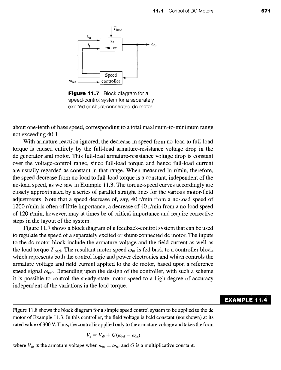
Figure
11.7 Block diagram for a
speed-control system for a separately
excited or shunt-connected dc motor.
about one-tenth of base speed, corresponding to a total maximum-to-minimum range
not exceeding 40:1.
With armature reaction ignored, the decrease in speed from no-load to full-load
torque is caused entirely by the full-load armature-resistance voltage drop in the
dc generator and motor. This full-load armature-resistance voltage drop is constant
over the voltage-control range, since full-load torque and hence full-load current
are usually regarded as constant in that range. When measured in r/min, therefore,
the speed decrease from no-load to full-load torque is a constant, independent of the
no-load speed, as we saw in Example 11.3. The torque-speed curves accordingly are
closely approximated by a series of parallel straight lines for the various motor-field
adjustments. Note that a speed decrease of, say, 40 r/min from a no-load speed of
1200 r/min is often of little importance; a decrease of 40 r/min from a no-load speed
of 120 r/min, however, may at times be of critical importance and require corrective
steps in the layout of the system.
Figure 11.7 shows a block diagram of a feedback-control system that can be used
to regulate the speed of a separately excited or shunt-connected dc motor. The inputs
to the dc-motor block include the armature voltage and the field current as well as
the load torque Tload. The resultant motor speed
O)m
is fed back to a controller block
which represents both the control logic and power electronics and which controls the
armature voltage and field current applied to the dc motor, based upon a reference
speed signal
O)ref.
Depending upon the design of the controller, with such a scheme
it is possible to control the steady-state motor speed to a high degree of accuracy
independent of the variations in the load torque.
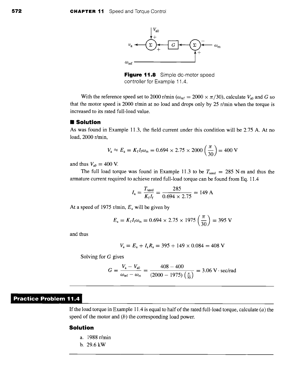
Figure 11.8 shows the block diagram for a simple speed control system to be applied to the dc
motor of Example 11.3. In this controller, the field voltage is held constant (not shown) at its
rated value of 300 V. Thus, the control is applied only to the armature voltage and takes the form
Va = Va0 -Jl" G(o)ref -- O-)m)
where Va0 is the armature voltage when
O) m =
O)re f and G is a multiplicative constant.
572
CHAPTER 11 Speed and Torque Control
~
0
OAref
09 m
Figure 11.8
Simple dc-motor speed
controller for Example 11.4.
With the reference speed set to 2000 r/min
((/)re f ~"
2000 x zr/30), calculate Va0 and G so
that the motor speed is 2000 r/min at no load and drops only by 25 r/min when the torque is
increased to its rated full-load value.
II
Solution
As was found in Example 11.3, the field current under this condition will be 2.75 A. At no
load, 2000 r/min,
Va ~' Ea = KflfWm -- 0.694 x 2.75 x 2000 3-0 = 400 V
and thus Va0 = 400 V.
The full load torque was found in Example 11.3 to be
Trate d =
285 N.m and thus the
armature current required to achieve rated full-load torque can be found from Eq. 11.4
Trate d 285
la = = = 149A
Kflf
0.694 x 2.75
At a speed of 1975 r/min, Ea will be given by
E.=KfIfo)m=0.694x2.75x 1975 3-0 =395V
and thus
Va = Ea "-[- laRa
--
395 + 149 × 0.084 = 408 V
Solving for G gives
Va-- Va0
G=
O)re f -- O) m
408 - 400
= - 3.06 V.
sec/rad
(2000 - 1975) (~)
)ractice Problem 1 1.,
If the load torque in Example I 1.4 is equal to half of the rated full-load torque, calculate (a) the
speed of the motor and (b) the corresponding load power.
Solution
a. 1988 r/min
b. 29.6 kW
11.1 Control of DC Motors 573
In the case of permanent-magnet dc motors, the field flux is, of course, fixed
by the permanent magnet (with the possible exception of any effects of temperature
changes on the magnet properties as the motor heats up). From Eqs. 11.3 and 11.4,
we see that the voltage generated voltage can be written in the form
Ea - Kmwm
(11.8)
and that the electromagnetic torque can be written as
Tmech
-"
Km la (11.9)
Comparison of Eqs. 11.8 and 11.9 with Eqs. 11.3 and 11.4 show that the analysis
of a permanent-magnet dc motor is identical to that of a shunt or separately excited
dc motor with the exception that the torque-constant Km must be substituted for the
term
Kf lf .
The permanent-magnet dc motor of Example 7.9 has an armature resistance of 1.03 ~ and a
torque constant Km = 0.22 V/(rad/sec). Assume the motor to be driving a constant power load
of 800 W (including rotational losses), and calculate the motor speed as the armature voltage
is varied from 40 to 50 V.
II
Solution
The motor power output (including rotational losses) is given by the product
Eala
and thus we
can write
Pload = Ea/a = Kmo)m/a
Solving for
O) m
gives
09 m --
The armature current can be written as
Ploa~
Kmta
(Va - Ea) (Va - Kmo)m)
Ia= --"
Ra Ra
These two equations can be combined to give an equation for
O) m
of the form
from which we can find
2 (K~) el°ad Ra
O) m --
09 m + K 2
=0
Va[ 1
1± 1-- U)
Recognizing that, if the voltage drop across the armature resistance is small, Va ~ Ea ---
Kmo)m, we
pick the positive sign and thus
ga I ~/ 4eloadga ]
O)m = ~-~m 1--~- 1-- V)
EXAMPLE 11.5
574
CHAPTER 11 Speed and Torque Control
Substituting values, we find that for Va = 40 V,
09 m "--
169.2 rad/sec (1616 r/min) and for
V a --- 50 V, 09 m -- 217.5 rad/sec (2077 r/min).
~ractice Problem 1 1 .!
Calculate the speed variation (in r/min) of the permanent-magnet dc motor of Example 11.5 if
the armature voltage is held constant at 50 V and the load power varies from 100 W to 500 W.
Solution
2077 r/min to 1540 r/min
11.1.2 Torque Control
As we have seen, the electromagnetic torque of a dc motor is proportional to the
armature current la and is given by
Tmech =
Kflfla
(11.10)
in the case of a separately excited or shunt motor and
Tmech ~--
Kmla
(11.11)
in the case of a permanent-magnet motor.
From these equations we see that torque can be controlled directly by controlling
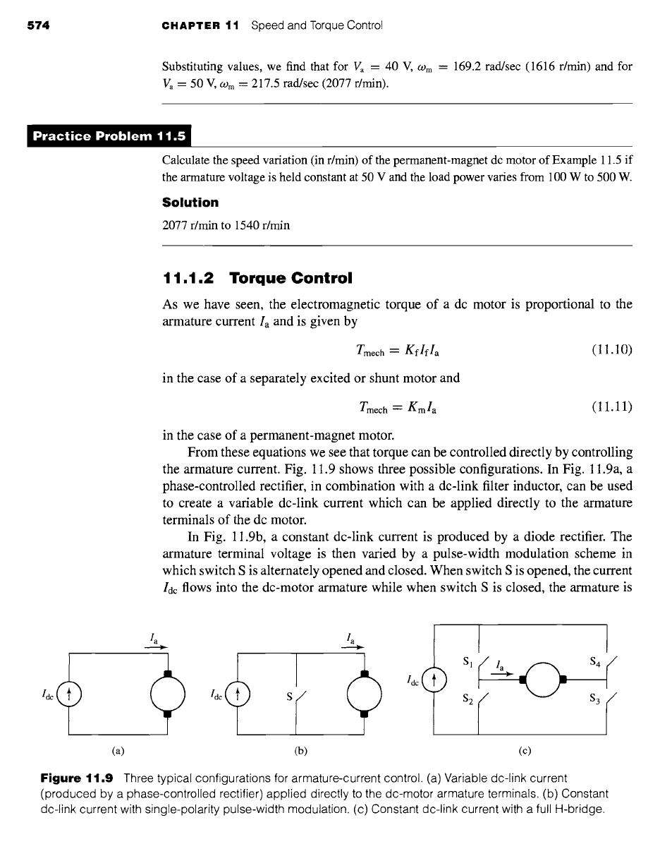
the armature current. Fig. 11.9 shows three possible configurations. In Fig. 11.9a, a
phase-controlled rectifier, in combination with a dc-link filter inductor, can be used
to create a variable dc-link current which can be applied directly to the armature
terminals of the dc motor.
In Fig. 11.9b, a constant dc-link current is produced by a diode rectifier. The
armature terminal voltage is then varied by a pulse-width modulation scheme in
which switch S is alternately opened and closed. When switch S is opened, the current
Idc flows into the dc-motor armature while when switch S is closed, the armature is
I
'de S r" "0 r
I
s,j_ 0 $4 r,
$2 ~/ $3 r /
(a) (b) (c)
Figure
11.9 Three typical configurations for armature-current control. (a) Variable dc-link current
(produced by a phase-controlled rectifier) applied directly to the dc-motor armature terminals. (b) Constant
dc-link current with single-polarity pulse-width modulation. (c) Constant dc-link current with a full H-bridge.
11.1 Control of DC Motors 575
Torque I Ia ]
controller I
>
O)ref ~,
Speed
controller
I T load
L i
motor [
l,f
: ; >
O9 m
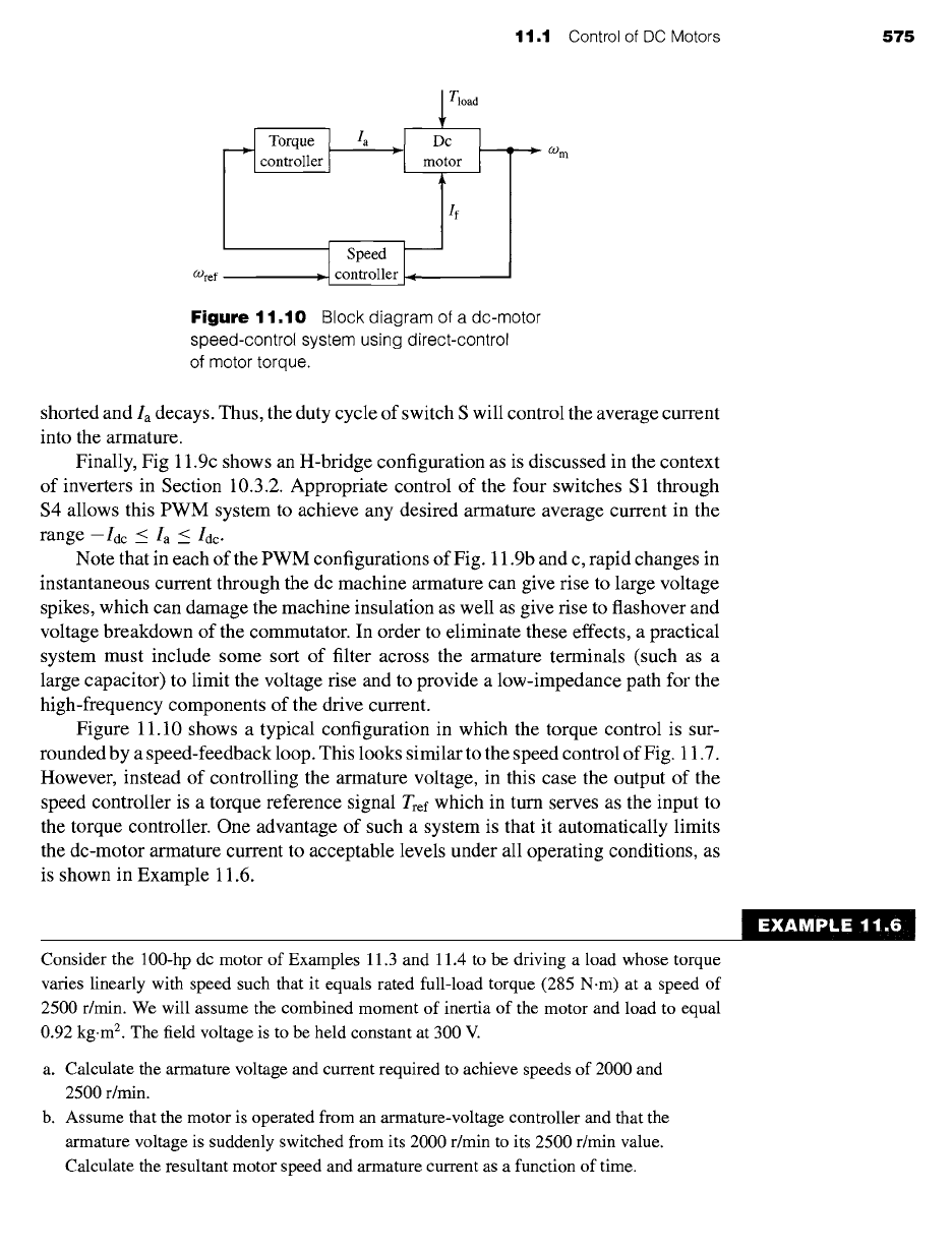
Figure
11.10 Block diagram of a dc-motor
speed-control system using direct-control
of motor torque.
shorted and Ia decays. Thus, the duty cycle of switch S will control the average current
into the armature.
Finally, Fig 11.9c shows an H-bridge configuration as is discussed in the context
of inverters in Section 10.3.2. Appropriate control of the four switches S 1 through
$4 allows this PWM system to achieve any desired armature average current in the
range--Idc < Ia < /de.
Note that in each of the PWM configurations of Fig. 11.9b and c, rapid changes in
instantaneous current through the dc machine armature can give rise to large voltage
spikes, which can damage the machine insulation as well as give rise to flashover and
voltage breakdown of the commutator. In order to eliminate these effects, a practical
system must include some sort of filter across the armature terminals (such as a
large capacitor) to limit the voltage rise and to provide a low-impedance path for the
high-frequency components of the drive current.
Figure 11.10 shows a typical configuration in which the torque control is sur-
rounded by a speed-feedback loop. This looks similar to the speed control of Fig. 11.7.
However, instead of controlling the armature voltage, in this case the output of the
speed controller is a torque reference signal Tref which in turn serves as the input to
the torque controller. One advantage of such a system is that it automatically limits
the dc-motor armature current to acceptable levels under all operating conditions, as
is shown in Example 11.6.
~ EXAMPLE 11~i6
Consider the 100-hp dc motor of Examples 11.3 and 11.4 to be driving a load whose torque
varies linearly with speed such that it equals rated full-load torque (285 N.m) at a speed of
2500 r/min. We will assume the combined moment of inertia of the motor and load to equal
0.92 kg.m 2. The field voltage is to be held constant at 300 V.
a. Calculate the armature voltage and current required to achieve speeds of 2000 and
2500 r/min.
b. Assume that the motor is operated from an armature-voltage controller and that the
armature voltage is suddenly switched from its 2000 r/min to its 2500 r/min value.
Calculate the resultant motor speed and armature current as a function of time.