Fitzgerald A.E. Electric Machinery
Подождите немного. Документ загружается.

596 CHAPTER 11 Speed and Torque Control
Stator
Rotor
(a)
(b)
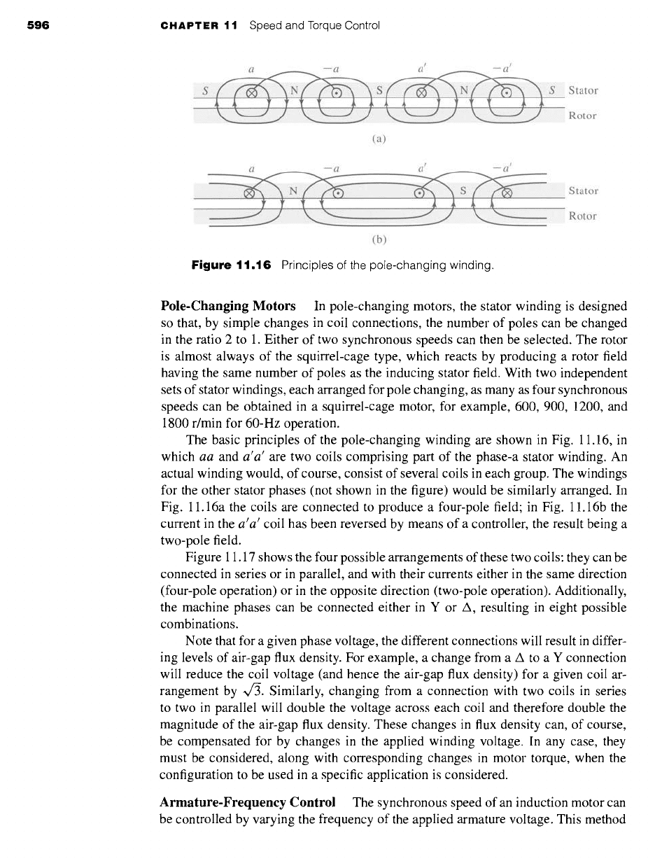
Figure
11.16 Principles of the pole-changing winding.
Stator
Rotor
Pole-Changing Motors
In pole-changing motors, the stator winding is designed
so that, by simple changes in coil connections, the number of poles can be changed
in the ratio 2 to 1. Either of two synchronous speeds can then be selected. The rotor
is almost always of the squirrel-cage type, which reacts by producing a rotor field
having the same number of poles as the inducing stator field. With two independent
sets of stator windings, each arranged for pole changing, as many as four synchronous
speeds can be obtained in a squirrel-cage motor, for example, 600, 900, 1200, and
1800 r/min for 60-Hz operation.
The basic principles of the pole-changing winding are shown in Fig. 11.16, in
which
aa
and
a'a'
are two coils comprising part of the phase-a stator winding. An
actual winding would, of course, consist of several coils in each group. The windings
for the other stator phases (not shown in the figure) would be similarly arranged. In
Fig. 11.16a the coils are connected to produce a four-pole field; in Fig. 11.16b the
current in the a'a' coil has been reversed by means of a controller, the result being a
two-pole field.
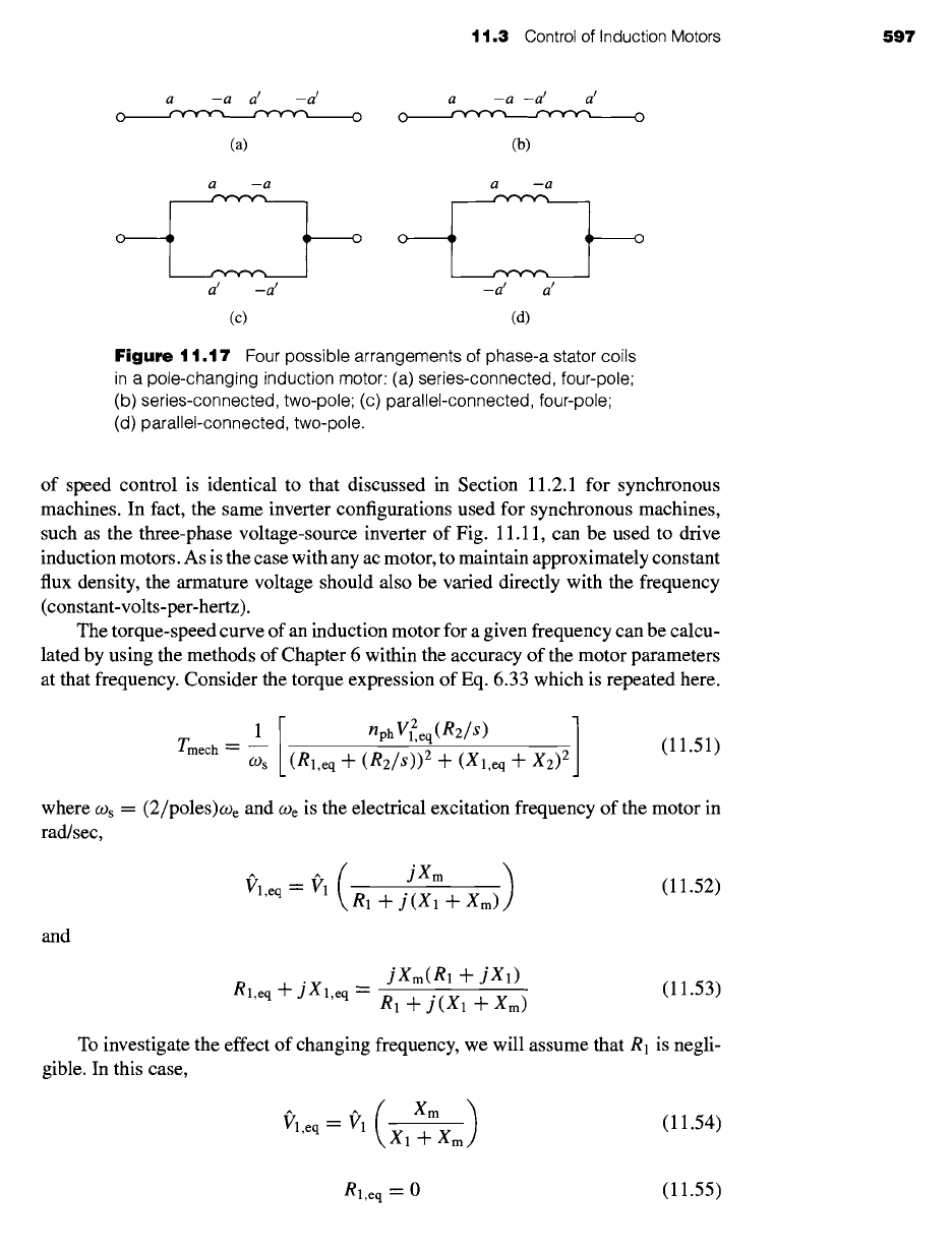
Figure 11.17 shows the four possible arrangements of these two coils: they can be
connected in series or in parallel, and with their currents either in the same direction
(four-pole operation) or in the opposite direction (two-pole operation). Additionally,
the machine phases can be connected either in Y or A, resulting in eight possible
combinations.
Note that for a given phase voltage, the different connections will result in differ-
ing levels of air-gap flux density. For example, a change from a A to a Y connection
will reduce the coil voltage (and hence the air-gap flux density) for a given coil ar-
rangement by ~. Similarly, changing from a connection with two coils in series
to two in parallel will double the voltage across each coil and therefore double the
magnitude of the air-gap flux density. These changes in flux density can, of course,
be compensated for by changes in the applied winding voltage. In any case, they
must be considered, along with corresponding changes in motor torque, when the
configuration to be used in a specific application is considered.
Armature-Frequency Control The synchronous speed of an induction motor can
be controlled by varying the frequency of the applied armature voltage. This method
11.3 Control of Induction Motors 597
a -a a t -a t a -a -a t a t
o ~ ~ o o ~ ~ o
(a) (b)
a -a a -a
o i i o o i I
T T T T
a t _a t _a t a t
(c) (d)
Figure
11.17 Four possible arrangements of phase-a stator coils
in a pole-changing induction motor: (a) series-connected, four-pole;
(b) series-connected, two-pole; (c)parallel-connected, four-pole;
(d) parallel-connected, two-pole.
of speed control is identical to that discussed in Section 11.2.1 for synchronous
machines. In fact, the same inverter configurations used for synchronous machines,
such as the three-phase voltage-source inverter of Fig. 11.11, can be used to drive
induction motors. As is the case with any ac motor, to maintain approximately constant
flux density, the armature voltage should also be varied directly with the frequency
(constant-volts-per-hertz).
The torque-speed curve of an induction motor for a given frequency can be calcu-
lated by using the methods of Chapter 6 within the accuracy of the motor parameters
at that frequency. Consider the torque expression of Eq. 6.33 which is repeated here.
1[
nph V?eq(R2/s) ]
Tmech "- ~
O)s (Rl,eq +
(R2/s)) 2 -Jr-
(Xl,eq -]" X2) 2
(11.51)
where Ogs = (2/poles)we and
O) e
is the electrical excitation frequency of the motor in
rad/sec,
jXm )
~'l,eq-- 91 R1
+
j(X1 +
Xm) (11.52)
and
jXm(R1 + jX1)
Rl,eq -q- jXl,eq
= R1 + j(X1 +
Xm)
(11.53)
To investigate the effect of changing frequency, we will assume that R1 is negli-
gible. In this case,
(Xm)
Vl,eq --~rl
Xl..~_Xm
(11.54)
Rl,eq -- 0
(11.55)
~o~
0 0 ~
~5"~ I
--< >
o
• o ~
~ ~ -.
~ 0 "~
O
_~:nZ o
Z~"
~D O
~E5
~~ ¢~
~ 0 0
~,o ~,
.'N Q.
c ~ o -
~ E b~
~<
o
• m
~ 0 ""
~c
0 0 0
::j- ~
~." 0
Tmech
I I I I I I
II
N
II
4~
N
II
N
II
4~
o0
N
II
o
N
I I I I I I I I
O
O
O
_~, ~
o = o
O
~a ~ n N
oi
+
~
~" ~ O
O ~ C~
O
~ ~ o
O
• ~ . = • :~ ..
z
"W
-I
I111
--L
.--L
"O
(D
(1)
Q.
o ~
_O
c-
CD
c~
O
O
11.3 Control of Induction Motors 599
Finally, we can write the motor slip as
COs -- O)m
S ~
O)s
poles (Awm) 2
O-)e
(11.60)
where Aogm = O)s -- Ogm is the difference between the synchronous and mechanical
angular velocities of the motor.
Substitution of Eqs. 11.57 through 11.60 into Eq. 11.51 gives
nph[ ( gl, eq) 0 ]2 (e2 / Ao))
Tmech--"
[(2o~O)(R2/A(.o)] 2
(11.61)
poles "]" [(Xl,eq "+- X2)012
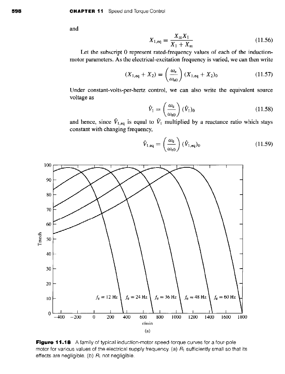
Equation 11.61 shows the general trend in which we see that the frequency
dependence of the torque-speed characteristic of an induction motor appears only in
the term
R2/A~.
Thus, under the assumption that R1 is negligible, as the electrical
supply frequency to an induction motor is changed, the shape of the speed-torque
curve as a function of AoJ (the difference between the synchronous speed and the
motor speed) will remain unchanged. As a result, the torque-speed characteristic will
simply shift along the speed axis as
O) e
(fe) is varied.
A set of such curves is shown in Fig. 11.18a. Note that as the electrical frequency
(and hence the synchronous speed) is decreased, a given value of Aco corresponds to a
100 I I I I I I I I I I
I I
90
80
70
60
50
40
30
20
10
0 I
I I
-400 -200
fe--12Hz~ fe=24Hz~ fe=36Hz~ fe=48Hz~ fe=60Hz
I I
II
0 200 400
] I
600
r/min
(b)
I I I I II I
800 1000 1200 1400 1600
1800
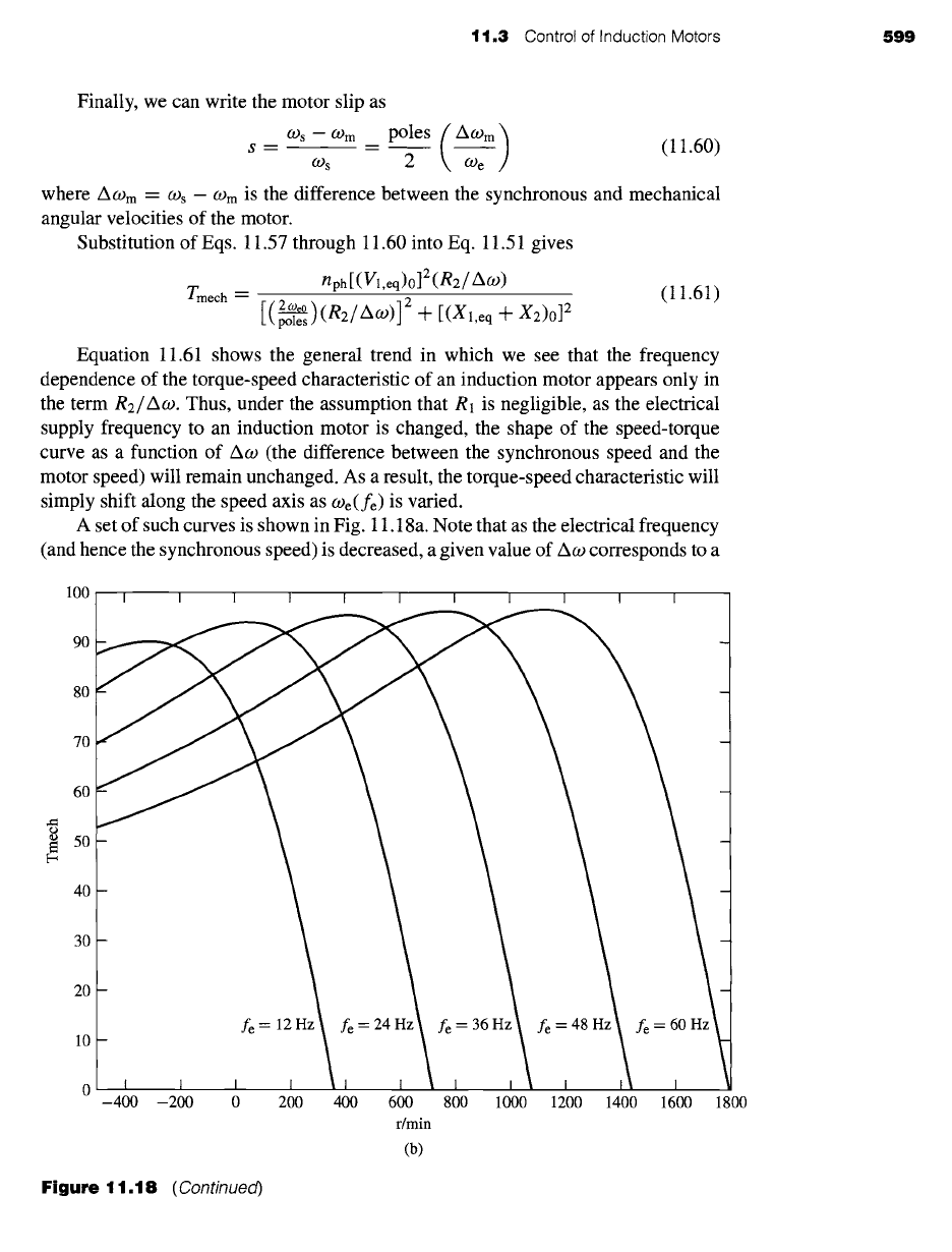
Figure
11.18 (Continued)
600
CHAPTER 11 Speed and Torque Control
larger slip. Thus, for example, if the peak torque of a four-pole motor driven at 60 Hz
occurs at 1638 r/min, corresponding to a slip of 9 percent, when driven at 30 Hz, the
peak torque will occur at 738 r/min, corresponding to a slip of 18 percent.
In practice, the effects of R1 may not be fully negligible, especially for large
values of slip. If this is the case, the shape of the speed-torque curves will vary
somewhat with the applied electrical frequency. Figure 11.18b shows a typical family
of curves for this case.
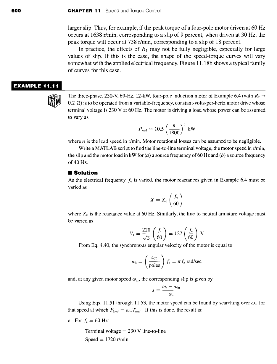
!XAMPLE 11.1'
The three-phase, 230-V, 60-Hz, 12-kW, four-pole induction motor of Example 6.4 (with
R2 '-
0.2 ffa) is to be operated from a variable-frequency, constant-volts-per-hertz motor drive whose
terminal voltage is 230 V at 60 Hz. The motor is driving a load whose power can be assumed
to vary as
(n)3
P, oad -- 10.5 1-~
kW
where n is the load speed in r/min. Motor rotational losses can be assumed to be negligible.
Write a MATLAB script to find the line-to-line terminal voltage, the motor speed in r/min,
the slip and the motor load in kW for (a) a source frequency of 60 Hz and (b) a source frequency
of 40 Hz.
II
Solution
As the electrical frequency fe is varied, the motor reactances given in Example 6.4 must be
varied as
X = Xo
where Xo is the reactance value at 60 Hz. Similarly, the line-to-neutral armature voltage must
be varied as
220 ( fe ) = 127 ILl
V
From Eq. 4.40, the synchronous angular velocity of the motor is equal to
co, = p-~es fc = Zrfe rad/sec
and, at any given motor speed
O.)m,
the corresponding slip is given by
09 s m O) m
S---
O)s
Using Eqs. 11.51 through 11.53, the motor speed can be found by searching over
09 m
for
that speed at which Pl,,,0 = COrn Tmech. If this is done, the result is:
a. For fe = 60 Hz:
Terminal voltage = 230 V line-to-line
Speed = 1720 r/min
t 1.3 Control of Induction Motors
601
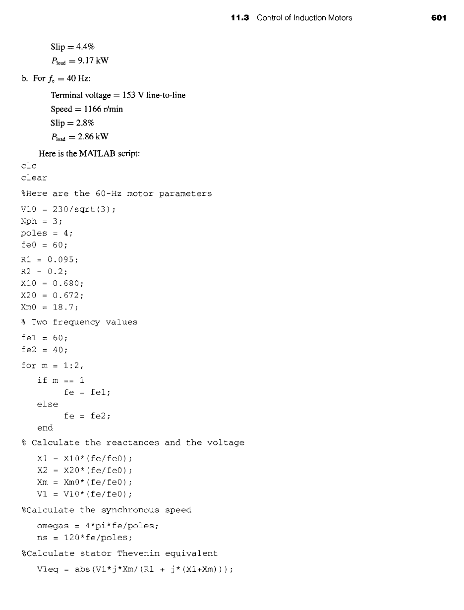
Slip = 4.4%
Ploaa = 9.17 kW
b. For fe = 40 HZ:
Terminal voltage = 153 V line-to-line
Speed
= 1166 r/min
Slip = 2.8%
Pload = 2.86 kW
Here
is the MATLAB script:
c1c
clear
%Here are the 60-Hz motor parameters
VI0 = 230/sqrt(3) ;
Nph = 3;
poles = 4 ;
fe0 = 60 ;
R1 = 0.095;
R2 = 0.2;
XI0 = 0.680;
X20 = 0.672;
Xm0 = 18.7;
% Two frequency values
fel = 60 ;
fe2 = 40 ;
for m = 1:2,
if m== 1
fe = fel ;
else
fe = fe2 ;
end
% Calculate the reactances and the voltage
Xl = Xl0*(fe/fe0) ;
X2 = X20*(fe/fe0) ;
Xm = Xm0* (fe/fe0) ;
Vl = Vl0*(fe/fe0) ;
%Calculate the synchronous speed
omegas = 4*pi*fe/poles;
ns = 120*fe/poles;
%Calculate stator Thevenin equivalent
Vleq = abs(Vl*j*Xm/(ml + j*(Xl+Xm)) ) ;
602 CHAPTER 11 Speed and Torque Control
Zleq : j*Xm*(RI+j*XI)/(RI + j*(Xl+Xm)) ;
Rleq = real(Zleq) ;
Xleq = imag(Zleq) ;
%Search over the slip until the Pload = Pmech
slip = 0. ;
error : 1 ;
while error >= 0;
slip = slip + 0.00001;
rpm = ns*(1-slip) ;
omegam = omegas* (1-slip) ;
Tmech = (i/omegas)*Nph*Vleq^2 *(R2/slip) ;
Tmech : Tmech/( (Rl+R2/slip)^2 + (XI+X2)^2) ;
Pmech = Tmech*omegam;
Pload = 10.5e3*(rpm/1800)^3;
error = Pload- Pmech;
end %End of while loop
fprintf('\nFor fe : %g [Hz] : ',fe)
fprintf('\n Terminal voltage = %g [V i-I] ',Vl*sqrt(3))
fprintf('\n rpm = %g',rpm)
fprintf('\n slip = %g [percent] ',100*slip)
fprintf('\n Pload : %g [kW] ',Pload/1000)
fprint f ( ' \n\n' )
end
Repeat Example 11.11 for a source frequency of 50 Hz.
Solution
Terminal voltage = 192 V line-to-line
Speed = 1447 r/min
Slip = 3.6%
eloacl "- 5.45 kW
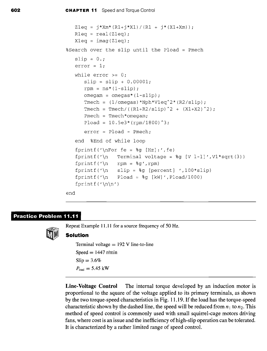
Line-Voltage Control The internal torque developed by an induction motor is
proportional to the square of the voltage applied to its primary terminals, as shown
by the two torque-speed characteristics in Fig. 11.19. If the load has the torque-speed
characteristic shown by the dashed line, the speed will be reduced from n l to n2. This
method of speed control is commonly used with small squirrel-cage motors driving
fans, where cost is an issue and the inefficiency of high-slip operation can be tolerated.
It is characterized by a rather limited range of speed control.
11.3 Control of Induction Motors 603
~
~oad
n2 nl
Speed
Figure
11.19 Speed control by
means of line voltage.
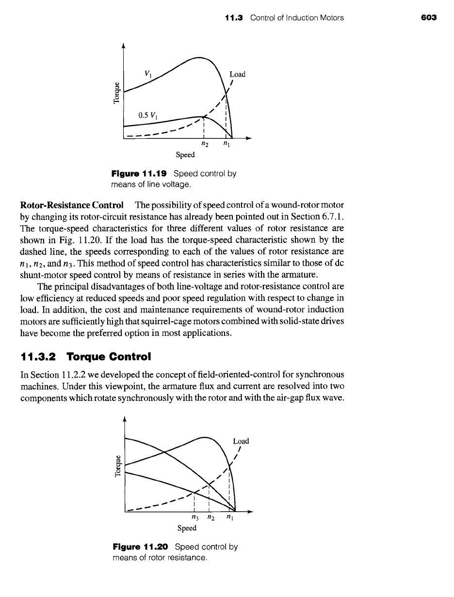
Rotor-Resistance Control The possibility of speed control of a wound-rotor motor
by changing its rotor-circuit resistance has already been pointed out in Section 6.7.1.
The torque-speed characteristics for three different values of rotor resistance are
shown in Fig. 11.20. If the load has the torque-speed characteristic shown by the
dashed line, the speeds corresponding to each of the values of rotor resistance are
n 1, n2, and n 3. This method of speed control has characteristics similar to those of dc
shunt-motor speed control by means of resistance in series with the armature.
The principal disadvantages of both line-voltage and rotor-resistance control are
low efficiency at reduced speeds and poor speed regulation with respect to change in
load. In addition, the cost and maintenance requirements of wound-rotor induction
motors are sufficiently high that squirrel-cage motors combined with solid-state drives
have become the preferred option in most applications.
11.3.2 Torque Control
In Section 11.2.2 we developed the concept of field-oriented-control for synchronous
machines. Under this viewpoint, the armature flux and current are resolved into two
components which rotate synchronously with the rotor and with the air-gap flux wave.
~
a
¢,
n 3 n2 nl
Speed
Figure
11.20 Speed control by
means of rotor resistance.
604 CHAPTER 11 Speed and Torque Control
The components of armature current and flux which are aligned with the field-winding
are referred to as
direct-axis components
while those which are perpendicular to this
axis are referred to as
quadrature-axis components.
It turns out that the same viewpoint which we applied to synchronous machines
can be applied to induction machines. As is discussed in Section 6.1, in the steady-
state the mmf and flux waves produced by both the rotor and stator windings of an
induction motor rotate at synchronous speed and in synchronism with each other.
Thus, the torque-producing mechanism in an induction machine is equivalent to that
of a synchronous machine. The difference between the two is that, in an induction
machine, the rotor currents are not directly supplied but rather are induced as the
induction-motor rotor slips with respect to the rotating flux wave produced by the
stator currents.
To examine the application of field-oriented control to induction machines, we
begin with the dq0 transformation of Section C.3 of Appendix C. This transformation
transforms both the stator and rotor quantities into a synchronously rotating reference
frame. Under balanced-three-phase, steady-state conditions, zero-sequence quantities
will be zero and the remaining direct- and quadrature-axis quantites will be constant.
Hence the flux-linkage current relationships of Eqs. C.52 through C.58 become
)~D = LSiD +
LmiDR (11.62)
)~Q = LSiQ +
LmiQR (11.63)
)~DR --
LmiD +
LRiDR (11.64)
~.QR =
LmiQ +
LRiQR (11.65)
In these equations, the subscripts D, Q, DR, and QR represent the constant
values of the direct- and quadrature-axis components of the stator and rotor quantities
respectively. It is a straight-forward matter to show that the inductance parameters
can be determined from the equivalent-circuit parameters as
Xm0
Lm = (11.66)
O)e0
XI0
Ls -- Lm -k--
(11.67)
(-Oe0
X20
LR -- Lm -~--
(11.68)
O)e0
where the subscript 0 indicates the rated-frequency value.
The transformed voltage equations Eqs. C.63 through C.68 become
VD -- RaiD --
COe~.Q (11.69)
VQ -- RaiQ 4- O)e~,D (11.70)
0 = RaRiDR -- (We
- O)me)~,QR
(11.71)
0 = RaRiQR + (We- O)me)~,DR
(11.72)
t 1.3 Control of Induction Motors 605
where one can show that the resistances are related to those of the equivalent circuit
as
and
Ra
= R1 (11.73)
RaR = R2 (11.74)
For the purposes of developing a field-oriented-control scheme, we will begin
with the torque expression of Eq. C.70
3 (poles) (Lm)
Tmech = ~ 2 -~R (ZDRiq -- ~.QRid) (11.75)
For the derivation of the dq0 transformation in Section C.3, the angular velocity
of the reference frame was chosen to the synchronous speed as determined by the
stator electrical frequency We. It was not necessary for the purposes of the derivation
to specify the absolute angular location of the reference frame. It is convenient at this
point to choose the direct axis of the reference frame aligned with the rotor flux.
If this is done
~QR -- 0
and the torque expression of Eq. 11.75 becomes
3
Tmech 2
(poles
= 2 ) (~-~) ~.DRiQ
From Eq. 11.71 we see that
/DR = 0
and thus
(11.76)
and
(11.77)
(11.78)
~,DR =
LmiD
(11.79)
~,D =
LSiD (11.80)
From Eqs. 11.79 and 11.80 we see that by choosing
set ~,QR = 0
and thus aligning
the synchronously rotating reference frame with the axis of the rotor flux, the direct-
axis rotor flux (which is, indeed, the total rotor flux) as well as the direct-axis flux are
determined by the direct-axis component of the armature current. Notice the direct
analogy with a dc motor. In a dc motor, the field- and direct-axis armature fluxes are
determined by the field current and in this field-oriented control scheme, the rotor
and direct-axis armature fluxes are determined by the direct-axis armature current.
In other words, in this field-oriented control scheme, the direct-axis component of
armature current serves the same function as the field current in a dc machine.
The torque equation, Eq. 11.77, completes the analogy with the dc motor. We see
that once the rotor direct-axis flux ~.DR is set by the direct-axis armature current, the