Fitzgerald A.E. Electric Machinery
Подождите немного. Документ загружается.

606 CHAPTER 11 Speed and Torque Control
torque is then determined by the quadrature-axis armature current just as the torque
is determined by the armature current in a dc motor.
In a practical implementation of the technique which we have derived, the direct-
and quadrature-axis currents iD and iQ must be transformed into the three motor phase
currents ia(t), ib(t), and
it(t).
This can be done using the inverse dq0 transformation
of Eq. C.48 which requires knowledge of 0s, the electrical angle between the axis of
phase a, and the direct-axis of the synchronously rotating reference frame.
Since it is not possible to measure the axis of the rotor flux directly, it is necessary
to calculate 0s, where 0s = (Det q-
00 as
given by Eq. C.46. Solving Eq. 11.72 for
(D e
gives
(ion)
(De = (Dme -- RaR ~DR (11.81)
From Eq. 11.65 with ~.QR = 0 we see that
iQR = -- iQ (11.82)
Eq. 11.82 in combination with Eq. 11.79 then gives
RaR ( i___QQ ) 1 (i~D)
(De = 09me "~- -~R iD = 09me -~- "t'R
(11.83)
where rR =
LR/RaR
is the rotor time constant.
We can now integrate Eq. 11.83 to find
[ 1 (/Q)
0S = (Dme "~- -- t
+ 00 (11.84)
rR
where 0s indicates the calculated value of 0s (often referred to as the
estimated value
of 0s). In the more general dynamic sense
J0'I ' (i°)l
0S =
(Dme + --
dt'
+ 00 (11.85)
rR iD
Note that both Eqs. 11.84 and 11.85 require knowledge of 00, the value of 0s at
t = 0. Although we will not prove it here, it turns out that in a practical implementation,
the effects of an error in this initial angle decay to zero with time, and hence it can
be set to zero without any loss of generality.
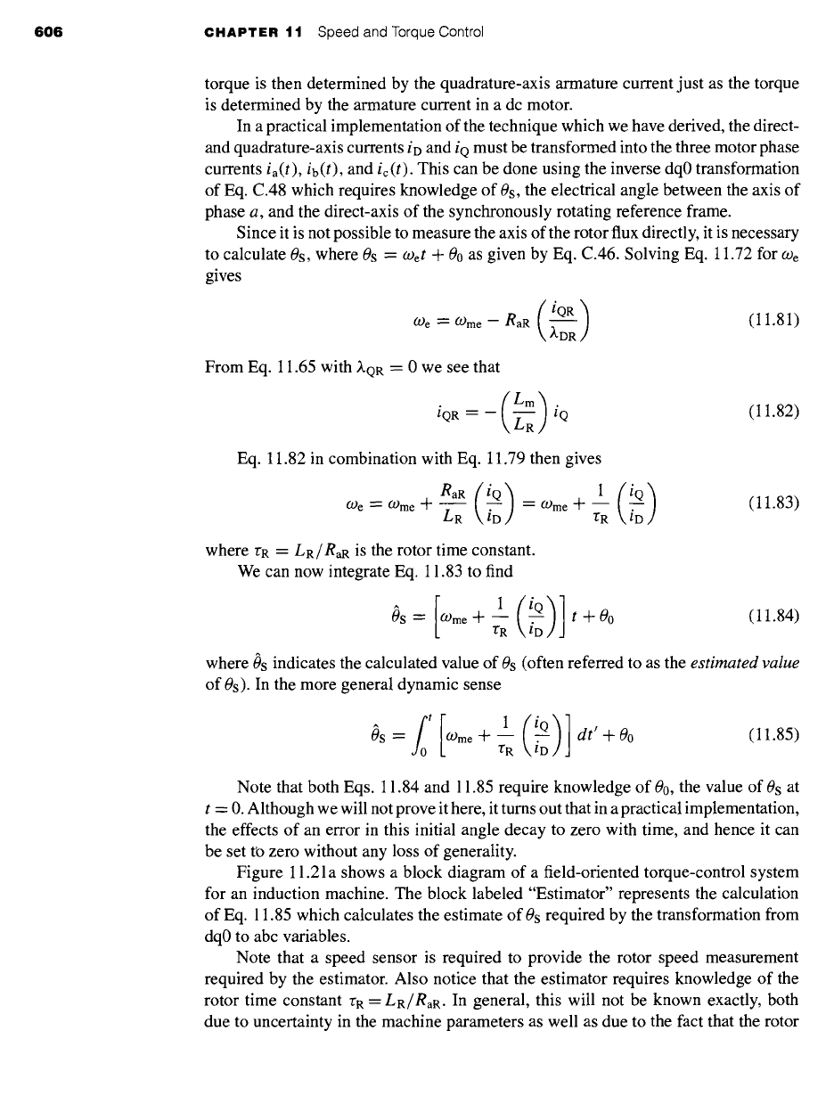
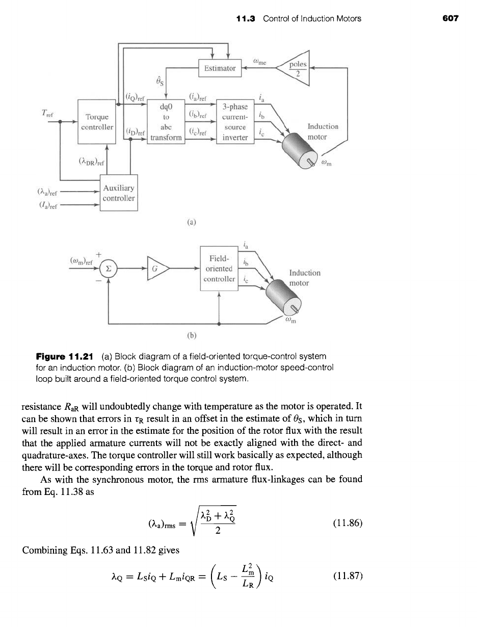
Figure 11.21 a shows a block diagram of a field-oriented torque-control system
for an induction machine. The block labeled "Estimator" represents the calculation
of Eq. 11.85 which calculates the estimate of 0s required by the transformation from
dq0 to abc variables.
Note that a speed sensor is required to provide the rotor speed measurement
required by the estimator. Also notice that the estimator requires knowledge of the
rotor time constant rR --
LR/RaR.
In general, this will not be known exactly, both
due to uncertainty in the machine parameters as well as due to the fact that the rotor
11.3 Control of Induction Motors 607
(iQ)ref
I I
Tref >
Torque t
I a
controller (
)ref trans
°R refT I
m
(~'a)ref ~,
Auxiliary
controller
(la)ref
I ~stimator I ~me
v •
,o
,c Induction
form ~oto~
~~m
(a)
(O)m)ref +~-~ _ ~,,,,~ _ ~.i~ld- ia
---'~_ z,J------~ ~ Oo~~" inodUC;ion
~m
/ Wm
(b)
Figure
11.21 (a) Block diagram of a field-oriented torque-control system
for an induction motor. (b) Block diagram of an induction-motor speed-control
loop built around a field-oriented torque control system.
resistance RaR will undoubtedly change with temperature as the motor is operated. It
can be shown that errors in rR result in an offset in the estimate of 0s, which in turn
will result in an error in the estimate for the position of the rotor flux with the result
that the applied armature currents will not be exactly aligned with the direct- and
quadrature-axes. The torque controller will still work basically as expected, although
there will be corresponding errors in the torque and rotor flux.
As with the synchronous motor, the rms armature flux-linkages can be found
from Eq. 11.38 as
(~,a)rms -- 2
Combining Eqs. 11.63 and 11.82 gives
~,Q ~-
LSiQ + LmiQR = LS - LR//
(11.86)
(11.87)
608 CHAPTER
11 Speed and Torque Control
Substituting Eqs. 11.80 and 11.87 into Eq. 11.86 gives
Lst D + Ls - -ff~ i~
(~,a)rms = 2
(11.88)
Finally, as discussed in the footnote to Eq. 11.37, the rms line-to-neutral armature
voltage can be found as
Va -- ¢ vz + -¢ (RaiD - weXQ)2 + (RaiQ +
(RaiD_COe(LsL 2 2
__ Z--R'R )iQ)
2
+ (RaiQ + COeLsiD) 2
(11.89)
These equations show that the armature flux linkages and terminal voltage are
determined by both the direct- and quadrature-axis components of the armature cur-
rent. Thus, the block marked "Auxiliary Controller" in Fig. 11.21 a, which calculates
the reference values for the direct- and quadrature-axis currents, must calculate the
reference currents (iD)ref and (iQ)ref which achieve the desired torque subject to con-
straints on armature flux linkages (to avoid saturation in the motor), armature current,
(Ia)rms
--
v/(i 2 + i~)/2
(to avoid excessive armature heating) and armature voltage
(to avoid potential insulation damage).
Note that, as we discussed with regard to synchronous machines in Section 11.2.2,
the torque-control system of Fig. 11.21 a is typically imbedded within a larger control
loop. One such example is the speed-control loop of Fig. 11.21 b.
!XAMPLE 11.1:
The three-phase, 230-V, 60-Hz, 12-kW, four-pole induction motor of Example 6.7 and Exam-
ple 11.11 is to be driven by a field-oriented speed-control system (similar to that of Fig. 11.21b)
at a speed of 1740 r/min. Assuming the controller is programmed to set the rotor flux linkages
~.DR to the machine rated peak value, find the rms amplitude of the armature current, the elec-
trical frequency, and the rms terminal voltage, if the electromagnetic power is 9.7 kW and the
motor is operating at a speed of 1680 r/min.
II
Solution
We must first determine the parameters for this machine. From Eqs. I1.66 through Eq. 11.74
Xm0 18.7
Lm = = = 49.6 mH
coco
120zr
Xio
0.680
Ls = Lm + ~ = 49.6 mH + -- 51.41 mH
COco
120n"
X2o 0.672
LR = Lm + -- = 49.6 mH + = 51.39 mH
We( )
1207r
R, = RI = 0.095 f2
R~R = R2
-- 0.2 g2

t t,3 Control of Induction Motors
609
The rated rms line-to-neutral terminal voltage for this machine is 230/~/3 = 132.8 V and
thus the peak rated flux for this machine is
%//'2(Va)rate d %//2 X 132.8
(~rated)peak "-" = "-" 0.498 Wb
o) e 1207r
For the specified operating condition
O) m = /'/ ~-~ =
1680 = 176 rad/sec
and the mechanical torque is
emech
9.7 x 10³
Tmech = = =
55.1 N. m
60 m
176
From Eq. 11.77, with/~DR
= /~rated =
0.498 Wb
2 2 LR
iQ ~ (p--~es)(~mm)(Tmech
2 (2) (51"39x10-3) (55"1) =38.2 A
= 3 4 49.6 x 10 .3 0.498
From Eq. 11.79,
~.DR 0.498
iD = = = 10.0 A
Lm 49.6 x 10 -3
The rms armature current is thus
~/
i 2 + i~ ~ 10.02 +
38.22
/a= 2 = 2
= 27.9 A
The electrical frequency can be found from Eq. 11.81
O')e = O')me "~- -~R ~D
With
09me ---
(poles/2)COm = 2 x 176 = 352 rad/sec
(
60 e =
352 + 51.39 ×
10 -3
l'i-~.0J = 367 rad/sec
and fe = (-Oe/(2~) --- 58.4 HZ.
Finally, from Eq. 11.89, the rms line-to-neutral terminal voltage
L2 ~ ie n t- (RaiQ n t- (-OeLsiD) 2
RaiD
-- O)e Ls -- I~i~ ,I
Va= 2
= 140.6 V line-to-neutral = 243.6 V line-to-line
610 CHAPTER
11 Speed and Torque Control
~ractice Problem 1 1.1:
Consider again the induction motor and field-oriented-control system of Example 11.12. As-
sume that the speed is readjusted to 1700 r/min and that the electromagnetic power is known to
increase to 10.0 kW. Find the rms amplitude of the armature current, the electrical frequency,
and the rms terminal voltage for this new operating condition.
Solution
Armature current = 28.4 A
fe = 59.1 Hz
Terminal voltage = 142.5 V line-to-neutral = 246.9 V line-to-line
The ability to independently control the rotor flux and the torque has important
control implications. Consider, for example, the response of the direct-axis rotor flux
to a change in direct-axis current. Equation C.66, with )~qR -- 0, becomes
dZdR
0-- RaRidR -k-~ (11.90)
dt
Substituting for/dR in terms of
~.OR
)~dR-
Lmid
/dR = (11.91)
LR
gives a differential equation for the rotor flux linkages
~-DR
d~'dR ( eaR ) ( tm )
d ----~ -F -~R
)~dR -- ~R
id (11.92)
From Eq. 11.92 we see that the response of the rotor flux to a step change in direct-
axis current id is relatively slow; )~dR will change exponentially with the rotor time
constant of rR --
LR/RaR.
Since the torque is proportional to the product ~.dRiq we see
that fast torque response will be obtained from changes in iq. Thus, for example, to
implement a step change in torque, a practical control algorithm might start with a step
change in (iQ)ref to achieve the desired torque change, followed by an adjustment in
(iD)ref (and hence ~.dR) to readjust the armature current or terminal voltage as desired.
This adjustment in (iD)ref would be coupled with a compensating adjustment in (iQ)ref
to maintain the torque at its desired value.
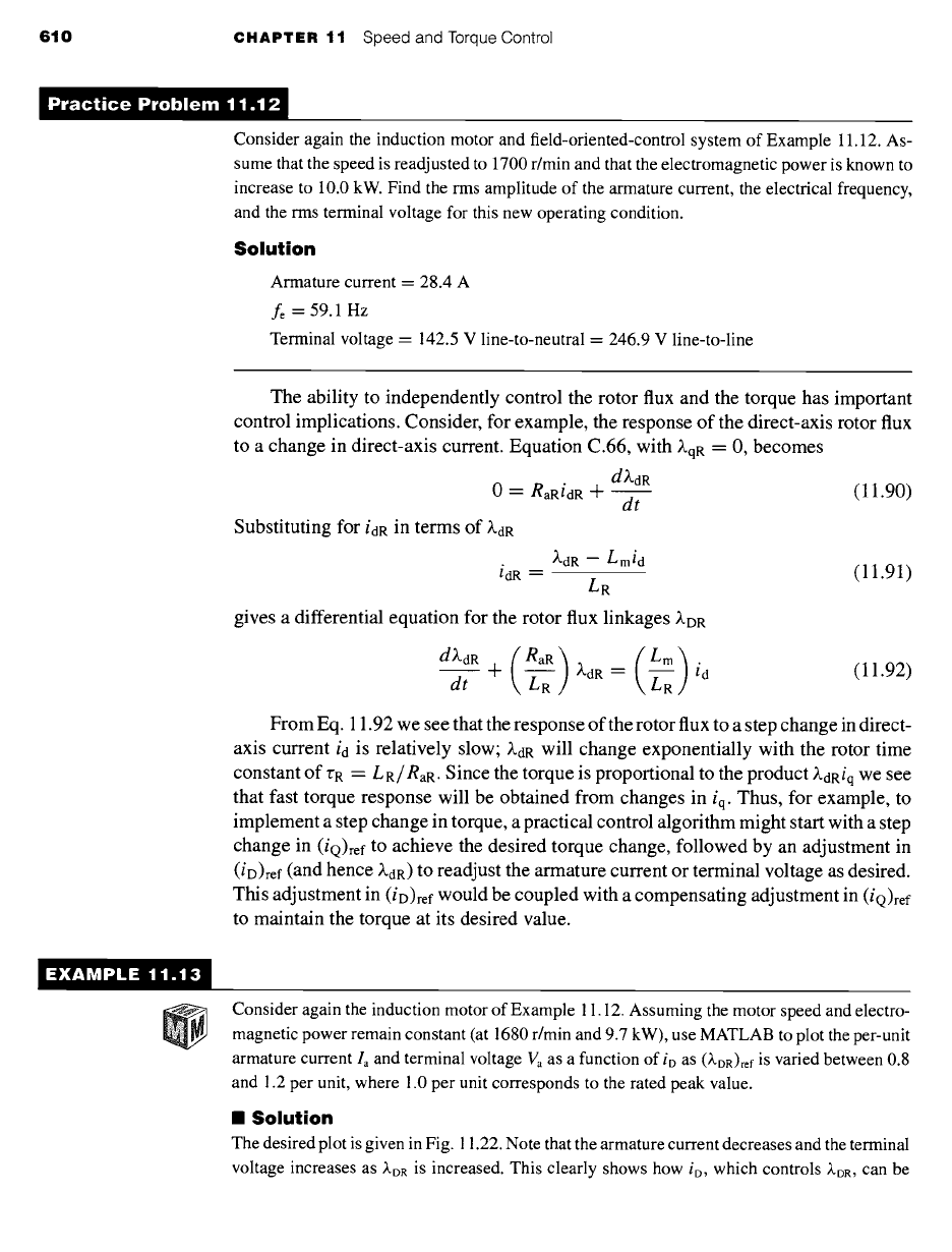
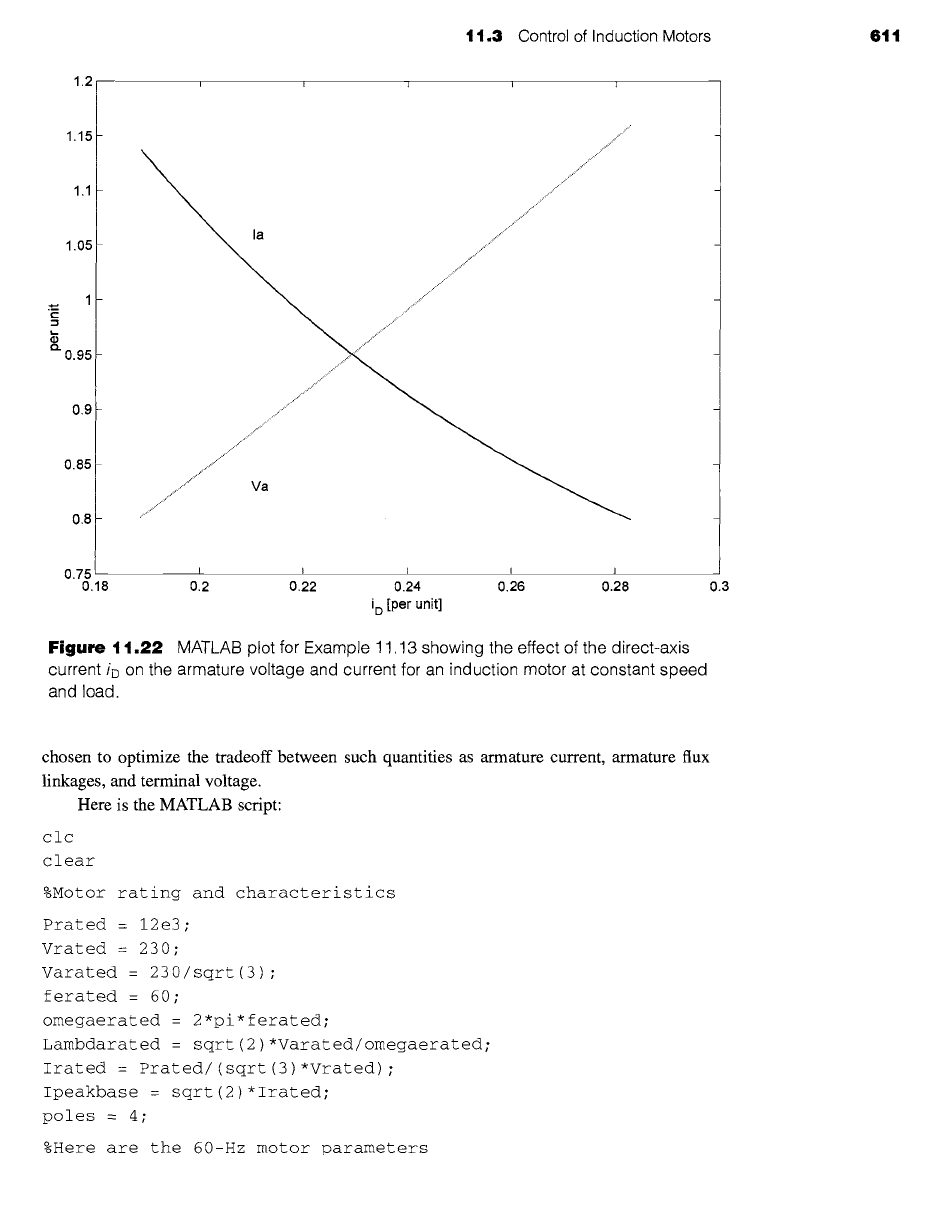
EXAMPLE 11.13
Consider again the induction motor of Example 11.12. Assuming the motor speed and electro-
magnetic power remain constant (at 1680 r/min and 9.7 kW), use MATLAB to plot the per-unit
armature current la and terminal voltage Va as a function of io as (~OR)ref is varied between 0.8
and 1.2 per unit, where 1.0 per unit corresponds to the rated peak value.
II Solution
The desired plot is given in Fig. 11.22. Note that the armature current decreases and the terminal
voltage increases
as ~DR
is increased. This clearly shows how io, which controls kDR, can be
11.3 Control of Induction Motors 611
1.2
1.15
1.1
1.05
0.95 -
0.9-
0.85 -
0.8-
Ha
.............. " ..................................... " ...................................................
0.75 - I I i i i
0.18 0.2 0.22 0.24 0.26 0.28
i D [per unit]
Figure
11.22 MATLAB plot for Example 11.13 showing the effect of the direct-axis
current iD on the armature voltage and current for an induction motor at constant speed
and load.
0.3
chosen to optimize the tradeoff between such quantifies as armature current, armature flux
linkages, and terminal voltage.
Here is the MATLAB script:
clc
clear
%Motor rating and characteristics
Prated = 12e3;
Vrated = 230;
Varated = 230/sqrt(3) ;
ferated = 60;
omegaerated = 2*pi*ferated;
Lambdarated = sqrt(2)*Varated/omegaerated;
Irated = Prated/(sqrt(3)*Vrated) ;
Ipeakbase = sqrt(2)*Irated;
poles : 4 ;
%Here are the 60-Hz motor parameters
612 CHAPTER 11 Speed and Torque Control
VI0 = Vrated/sqrt(3) ;
XI0 = 0.680;
X20 = 0.672;
Xm0 = 18.7;
R1 = 0.095;
R2 = 0.2;
%Calculate required dq0 parameters
Lm = Xm0/omegaerated;
LS = Lm + Xl0/omegaerated;
LR = Lm + X20/omegaerated;
Ra = RI;
RaR = R2 ;
% Operating point
n = 1680 ;
omegam = n*pi/30;
omegame = (poles/2)*omegam;
Pmech = 9.7e3;
Tmech = Pmech/omegam;
% Loop to plot over lambdaDR
for n = 1:41
lambdaDR = (0.8 + (n-1)*0.4/40)*Lambdarated;
lambdaDRpu (n) = lambdaDR/Lambdarated;
iQ = (2/3) * (2/poles) * (LR/Lm) * (Tmech/lambdaDR) ;
iD = (lambdaDR/Lm) ;
iDpu(n) = iD/Ipeakbase;
iQm = - (Lm/LR)*iQ;
Ia : sqrt((iD^2 + iQ^2)/2) ;
Iapu(n) = Ia/Irated;
omegae = omegame - (RaR/LR)*(iQ/iD) ;
fe(n) = omegae/ (2*pi) ;
Varms = sqrt( ((Ra*iD-omegae*(LS-Lm^2/LR)*iQ) ^2 + . ..
(Ra*iQ+ omegae*LS*iD)^2) /2) ;
Vapu(n) = Varms/Varated;
end
%Now plot
plot (iDpu, Iapu)
hold
plot(iDpu,Vapu, ' :')
hold
xlabel('i_D [per unit] ')
ylabel('per unit')
text(.21,1.06, 'Ia')
text (.21, .83, 'Va')
11.4 Control of Variable-Reluctance Motors 613
11.4 CONTROL OF VARIABLE-RELUCTANCE
MOTORS
Unlike dc and ac (synchronous or induction) machines, VRMs cannot be simply
"plugged in" to a dc or ac source and then be expected to run. As is dicussed in
Chapter 8, the phases must be excited with (typically unipolar) currents, and the
timing of these currents must be carefully correlated with the position of the rotor
poles in order to produce a useful, time-averaged torque. The result is that although
the VRM itself is perhaps the simplest of rotating machines, a practical VRM drive
system is relatively complex.
VRM drive systems are competitive only because this complexity can be realized
easily and inexpensively through power and microelectronic circuitry. These drive
systems require a fairly sophisticated level of controllability for even the simplest
modes of VRM operation. Once the capability to implement this control is available,
fairly sophisticated control features can be added (typically in the form of additional
software) at little additional cost, further increasing the competitive position of VRM
drives.
In addition to the VRM itself, the basic VRM drive system consists of the follow-
ing components: a rotor-position sensor, a controller, and an inverter. The function
of the rotor-position sensor is to provide an indication of shaft position which can be
used to control the timing and waveform of the phase excitation. This is directly anal-
ogous to the timing signal used to control the firing of the cylinders in an automobile
engine.
The controller is typically implemented in software in microelectronic (micro-
processor) circuitry. Its function is to determine the sequence and waveforms of the
phase excitation required to achieve the desired motor speed-torque characteristics. In
addition to set points of desired speed and/or torque and shaft position (from the shaft-
position sensor), sophisticated controllers often employ additional inputs including
shaft-speed and phase-current magnitude. Along with the basic control function of
determining the desired torque for a given speed, the more sophisticated controllers
attempt to provide excitations which are in some sense optimized (for maximum
efficiency, stable transient behavior, etc.).
The control circuitry consists typically of low-level electronics which cannot be
used to directly supply the currents required to excite the motor phases. Rather its
output consists of signals which control an inverter which in turn supplies the phase
currents. Control of the VRM is achieved by the application of an appropriate set of
currents to the VRM phase windings.
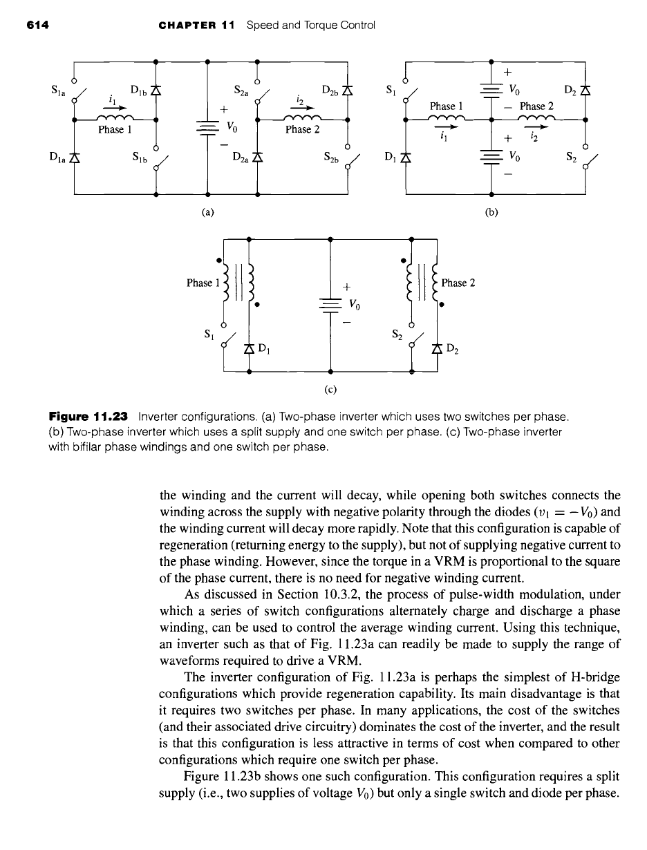
Figures 11.23a to c show three common configurations found in inverter systems
for driving VRMs. Note that these are simply H-bridge inverters of the type discussed
in Section 10.3. Each inverter is shown in a two-phase configuration. As is clear from
the figures, extension of each configuration to drive additional phases can be readily
accomplished.
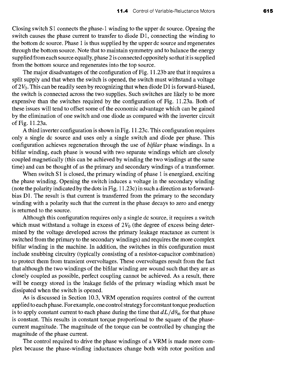
The configuration of Fig. 11.23a is perhaps the simplest. Closing switches Sla
and Slb connects the phase-1 winding across the supply (Vl = V0) and causes the
winding current to increase. Opening just one of the switches forces a short across
614 CHAPTER 11 Speed and Torque Control
A
Sla
I Phase 1
Dla~ Slb ~
S2a ~ i2 D2b i
+
vo
D2a S2b
w v
(a)
A
y ÷
S1 ../ VO D 2
-- Phase 2
F"Y"'V""V~
• ~
D1 , Vo $2
(b)
)
Phase I
)
Sl ( ]~ DI
/
w
m
m
w
(c)
+
Vo
$2
A
w
hase 2
Figure
11.23 Inverter configurations. (a) Two-phase inverter which uses two switches per phase.
(b) Two-phase inverter which uses a split supply and one switch per phase. (c) Two-phase inverter
with bifilar phase windings and one switch per phase.
the winding and the current will decay, while opening both switches connects the
winding across the supply with negative polarity through the diodes (Vl = -V0) and
the winding current will decay more rapidly. Note that this configuration is capable of
regeneration (returning energy to the supply), but not of supplying negative current to
the phase winding. However, since the torque in a VRM is proportional to the square
of the phase current, there is no need for negative winding current.
As discussed in Section 10.3.2, the process of pulse-width modulation, under
which a series of switch configurations alternately charge and discharge a phase
winding, can be used to control the average winding current. Using this technique,
an inverter such as that of Fig. 11.23a can readily be made to supply the range of
waveforms required to drive a VRM.
The inverter configuration of Fig. 11.23a is perhaps the simplest of H-bridge
configurations which provide regeneration capability. Its main disadvantage is that
it requires two switches per phase. In many applications, the cost of the switches
(and their associated drive circuitry) dominates the cost of the inverter, and the result
is that this configuration is less attractive in terms of cost when compared to other
configurations which require one switch per phase.
Figure 11.23b shows one such configuration. This configuration requires a split
supply (i.e., two supplies of voltage V0) but only a single switch and diode per phase.
11,4 Control of Variable-Reluctance Motors 6t5
Closing switch S 1 connects the phase-1 winding to the upper dc source. Opening the
switch causes the phase current to transfer to diode D 1, connecting the winding to
the bottom dc source. Phase 1 is thus supplied by the upper dc source and regenerates
through the bottom source. Note that to maintain symmetry and to balance the energy
supplied from each source equally, phase 2 is connected oppositely so that it is supplied
from the bottom source and regenerates into the top source.
The major disadvantages of the configuration of Fig. 11.23b are that it requires a
split supply and that when the switch is opened, the switch must withstand a voltage
of 2 V0. This can be readily seen by recognizing that when diode D 1 is forward-biased,
the switch is connected across the two supplies. Such switches are likely to be more
expensive than the switches required by the configuration of Fig. 11.23a. Both of
these issues will tend to offset some of the economic advantage which can be gained
by the elimination of one switch and one diode as compared with the inverter circuit
of Fig. 11.23a.
A third inverter configuration is shown in Fig. 11.23c. This configuration requires
only a single dc source and uses only a single switch and diode per phase. This
configuration achieves regeneration through the use of
bifilar
phase windings. In a
bifilar winding, each phase is wound with two separate windings which are closely
coupled magnetically (this can be achieved by winding the two windings at the same
time) and can be thought of as the primary and secondary windings of a transformer.
When switch S 1 is closed, the primary winding of phase 1 is energized, exciting
the phase winding. Opening the switch induces a voltage in the secondary winding
(note the polarity indicated by the dots in Fig. 11.23c) in such a direction as to forward-
bias D 1. The result is that current is transferred from the primary to the secondary
winding with a polarity such that the current in the phase decays to zero and energy
is returned to the source.
Although this configuration requires only a single dc source, it requires a switch
which must withstand a voltage in excess of 2V0 (the degree of excess being deter-
mined by the voltage developed across the primary leakage reactance as current is
switched from the primary to the secondary windings) and requires the more complex
bifilar winding in the machine. In addition, the switches in this configuration must
include snubbing circuitry (typically consisting of a resistor-capacitor combination)
to protect them from transient overvoltages. These overvoltages result from the fact
that although the two windings of the bifilar winding are wound such that they are as
closely coupled as possible, perfect coupling cannot be achieved. As a result, there
will be energy stored in the leakage fields of the primary winding which must be
dissipated when the switch is opened.
As is discussed in Section 10.3, VRM operation requires control of the current
applied to each phase. For example, one control strategy for constant torque production
is to apply constant current to each phase during the time that
dL/dOm
for that phase
is constant. This results in constant torque proportional to the square of the phase-
current magnitude. The magnitude of the torque can be controlled by changing the
magnitude of the phase current.
The control required to drive the phase windings of a VRM is made more com-
plex because the phase-winding inductances change both with rotor position and