Fitzgerald A.E. Electric Machinery
Подождите немного. Документ загружается.

'(e)
O1
(0) S1Jed 'L'V eldLu~xq
Jol
l!noJ!~) II, I.'V ~an§!.-I
r,_0_0 0_~-----,V~
O~'Of + ~0"0
00"£f+0"0I ~,~ 00"gf+0"0l A0~;I 0;l
00"£f
+ 0"01 A 0~;I
o~of + ~oo
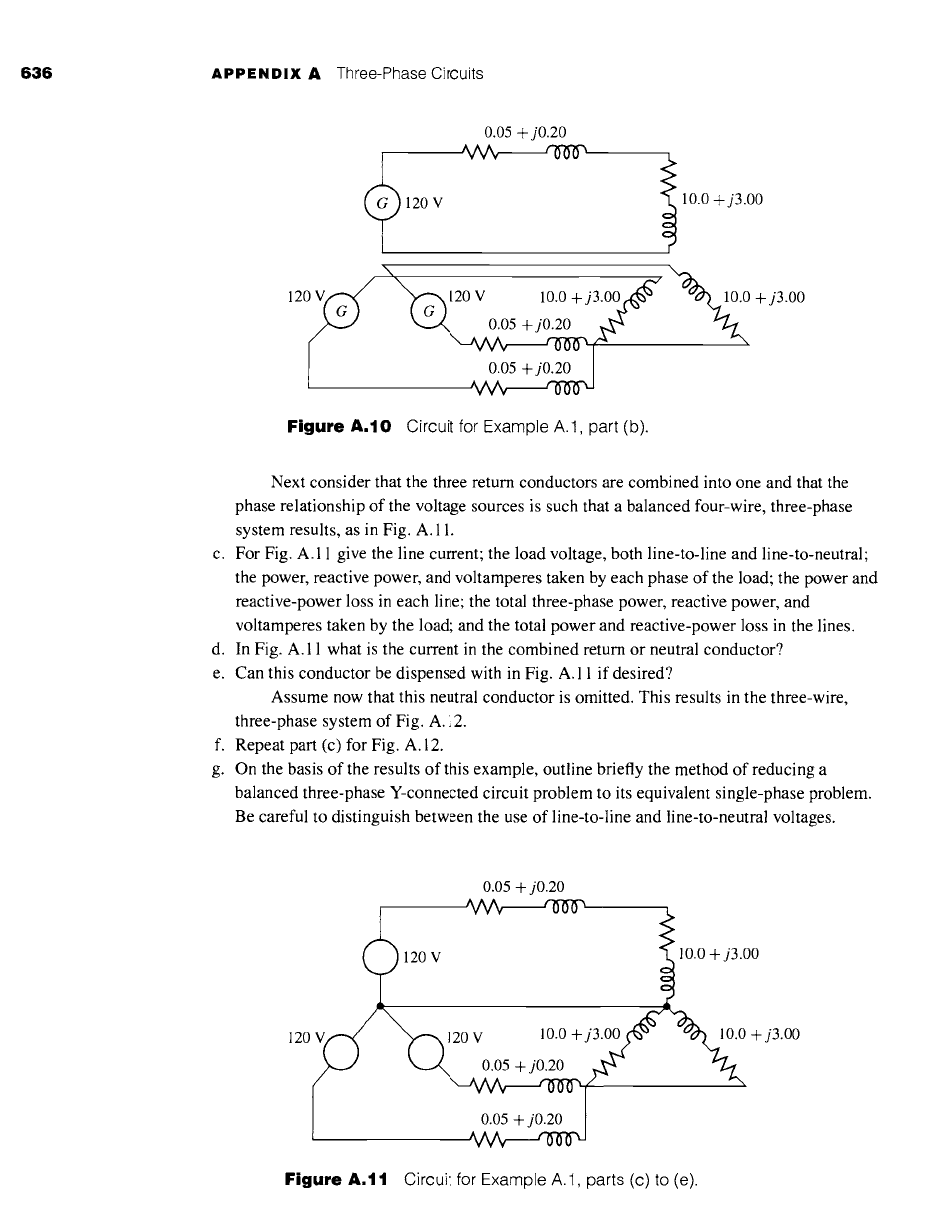
"Sa~I~IIOA l~Jlnau-ol-au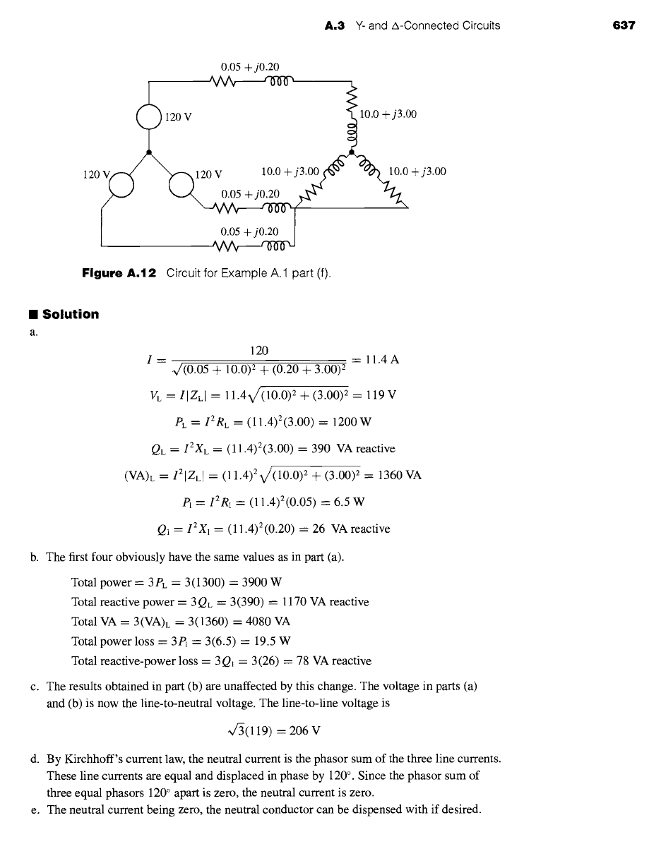
A.3
Y- and A-Connected Circuits
637
0.05 + j0.20
- l OV
I
^ A A _.~J-A-~WX
Figure
A.12 Circuit for Example A.1 part (f).
II Solution
a.
120
I= = ll.4A
~/(0.05 + 10.0) 2 +
(0.20 +
3.00) 2
VL = IIZLI = 11.4V/(10.0) 2 Jr (3.00) 2 = 119 V
PL = IZRL = (11.4)2(3.00) --- 1200 W
QL
= I2XL =
(11.4)2(3.00) = 390 VA reactive
(VA)L = I21ZLI
= (11.4)2v/(10.0) 2 + (3.00) 2 = 1360 VA
P1 = 12 R~ = (11.4) 2 (0.05) = 6.5 W
Q1 = 12X1 = (11.4) 2 (0.20) = 26 VA reactive
b. The first four obviously have the same values as in part (a).
Total power = 3PL = 3(1300) = 3900 W
Total reactive power = 3QL = 3(390) = 1170 VA reactive
Total VA = 3(VA)L = 3(1360) = 4080 VA
Total power loss = 3PI = 3(6.5) = 19.5 W
Total reactive-power loss = 3Q~ = 3(26) = 78 VA reactive
c. The results obtained in part (b) are unaffected by this change. The voltage in parts (a)
and (b) is now the line-to-neutral voltage. The line-to-line voltage is
~/3(119) = 206 V
d. By Kirchhoff's current law, the neutral current is the phasor sum of the three line currents.
These line currents are equal and displaced in phase by 120 °. Since the phasor sum of
three equal phasors 120 ° apart is zero, the neutral current is zero.
e. The neutral current being zero, the neutral conductor can be dispensed with if desired.
638 APPENDIX A Three-Phase Circuits
Since the presence or absence of the neutral conductor does not affect conditions, the
values are the same as in part (c).
A neutral conductor can be assumed, regardless of whether one is physically present.
Since the neutral conductor in a balanced three-phase circuit carries no current and hence
has no voltage drop across it, the neutral conductor should be considered to have zero
impedance. Then one phase of the Y, together with the neutral conductor, can be removed
for study. Since this phase is uprooted at the neutral, line-to-neutral voltages must be
used. This procedure yields the single-phase equivalent circuit, in which all quantities
correspond to those in one phase of the three-phase circuit. Conditions in the other two
phases being the same (except for the 120 ° phase displacements in the currents and
voltages), there is no need for investigating them individually. Line currents in the
three-phase system are the same as in the single-phase circuit, and total three-phase
power, reactive power, and voltamperes are three times the corresponding quantities in the
single-phase circuit. If line-to-line voltages are desired, they must be obtained by
multiplying voltages in the single-phase circuit by 4r3.
"XAMPLE A.'
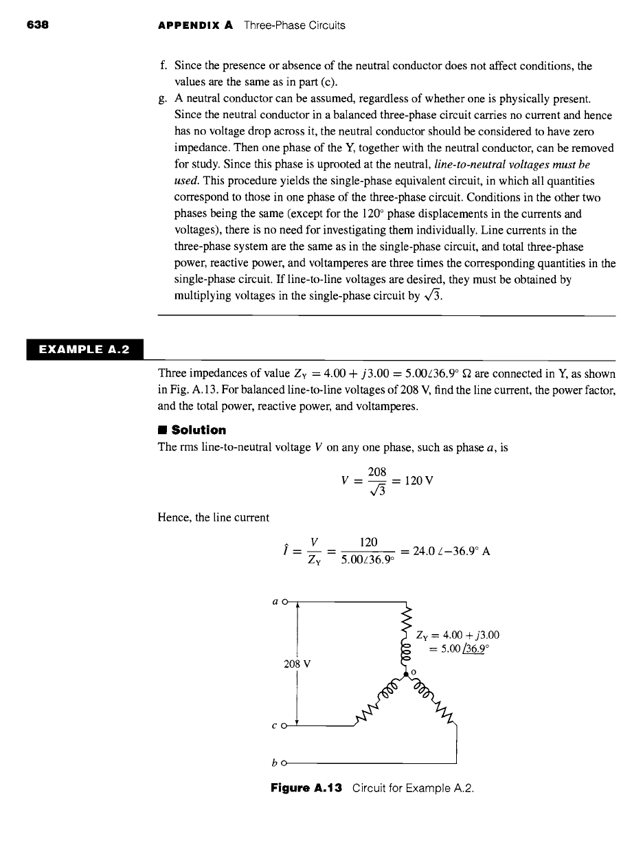
Three impedances of value Zv = 4.00 + j3.00 = 5.00L36.9 ° ~ are connected in Y, as shown
in Fig. A. 13. For balanced line-to-line voltages of 208 V, find the line current, the power factor,
and the total power, reactive power, and voltamperes.
m Solution
The rms line-to-neutral voltage V on any one phase, such as phase a, is
208
V = = 120V
Hence, the line current
y .__
V
Zv
120
= = 24.0 z-36.9 ° A
5.00z36.9 o
ao
208 V
CO
bo
Figure
A.13 Circuit for Example A.2.
A.3 Y- and A-Connected Circuits
639
and the power factor is equal to
Power factor = cos 0 = cos (-36.9 °) = 0.80 lagging
Thus
P = 312Ry = 3(24.0)2(4.00) = 6910 W
Q = 312Xy = 3(24.0)2(3.00) = 5180 VA reactive
VA =
3VI
= 3(120)(24.0) = 8640 VA
Note that phases a and c (Fig. A.13) do not form a simple series circuit. Consequently, the
current cannot be found by dividing 208 V by the sum of the phase-a and -c impedances. To
be sure, an equation can be written for voltage between points a and c by Kirchhoff's voltage
law, but this must be a phasor equation taking account of the 120 ° phase displacement between
the phase-a and phase-c currents. As a result, the method of thought outlined in Example A. 1
leads to the simplest solution.
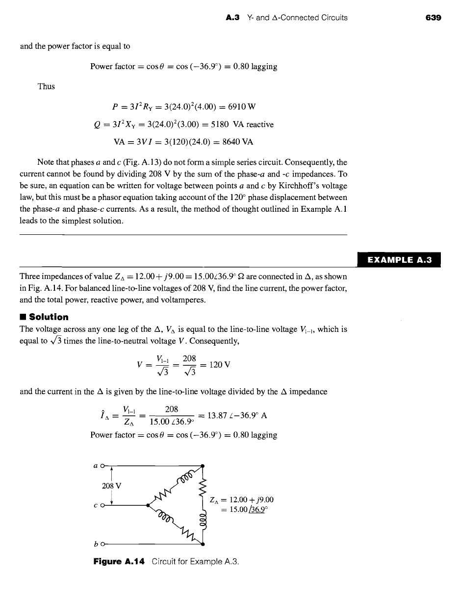
Three impedances of value ZA = 12.00+ j9.00 = 15.00/36.9 ° f2 are connected in A, as shown
in Fig. A.14. For balanced line-to-line voltages of 208 V, find the line current, the power factor,
and the total power, reactive power, and voltamperes.
II
Solution
The voltage across any one leg of the
A, VA
is equal to the line-to-line voltage V~_~, which is
equal to V/3 times the line-to-neutral voltage V. Consequently,
VI-1 208
V= = -- 120V
43
and the current in the A is given by the line-to-line voltage divided by the A impedance
i6 -- VI_I = 208
ZA 15.00/36.9 °
= 13.87/-36.9 ° A
Power factor = cos 0 = cos (-36.9 °) = 0.80 lagging
EXAMPLE: A.3 ~:
ao l
208
V
bo
Z A = 12.00 + j9.00
= 15.00/36.9 °
Figure
A.14 Circuit for Example A.3.
$40
APPENDIX A Three-Phase Circuits
From Eq. A.4 the phase current is equal to
I = ~/3IA = Vc3(13.87) = 24.0 A
Also
P = 3P/, = 3IZRA
= 3(13.87)2(12.00) = 6910 W
Q - 3QA = 3IzXA
= 3(13.87)2(9.00) = 5180VA reactive
and
VA = 3(VA)A = 3Vl-llA = 3(208)(13.87) = 8640 VA
Note that phases
ab
and
bc
do not form a simple series circuit, nor does the path
cba
form
a simple parallel combination with the direct path through the phase
ca.
Consequently, the
line current cannot be found by dividing 208 V by the equivalent impedance of Zca in parallel
with
Zab + Zbc.
Kirchhoff's-law equations involving quantities in more than one phase can
be written, but they must be phasor quantities taking account of the 120 ° phase displacement
between phase currents and phase voltages. As a result, the method outlined above leads to the
simplest solution.
Comparison of the results of Examples A.2 and A.3 leads to a valuable and
interesting conclusion. Note that the line-to-line voltage, line current, power factor,
total power, reactive power, and voltamperes are precisely equal in the two cases; in
other words, conditions viewed from the terminals A, B, and C are identical, and one
cannot distinguish between the two circuits from their terminal quantities. It will also
be seen that the impedance, resistance, and reactance per phase of the Y connection
(Fig. A.13) are exactly one-third of the corresponding values per phase of the A
connection (Fig. A. 14). Consequently, a balanced A connection can be replaced by a
balanced Y connection providing that the circuit constants per phase obey the relation
1
Zv - ~ Zzx (A.25)
Conversely, a Y connection can be replaced by a A connection provided Eq. A.25 is
satisfied. The concept of this Y-A equivalence stems from the general Y-A transfor-
mation and is not the accidental result of a specific numerical case.
Two important corollaries follow from this equivalence: (1) A general computa-
tional scheme for balanced circuits can be based entirely on Y-connected circuits or
entirely on A-connected circuits, whichever one prefers. Since it is frequently more
convenient to handle a Y connection, the former scheme is usually adopted. (2) In
the frequently occurring problems in which the connection is not specified and is not
pertinent to the solution, either a Y or a A connection may be assumed. Again the Y
connection is more commonly selected. In analyzing three-phase motor performance,
for example, the actual winding connections need not be known unless the investi-
gation is to include detailed conditions within the windings themselves. The entire
analysis can then be based on an assumed Y connection.
A.4 Analysis of Balanced Three-Phase Circuits; Single-Line Diagrams 641
A,4
ANALYSIS OF BALANCED THREE-PHASE
CIRCUITS; SINGLE-LINE DIAGRAMS
By combining the principle of A-Y equivalence with the technique revealed by Exam-
ple A. 1, a simple method of reducing a balanced three-phase-circuit problem to its
corresponding single-phase problem can be developed. All the methods of single-
phase-circuit analysis thus become available for its solution. The end results of the
single-phase analysis are then translated back into three-phase terms to give the final
results.
In carrying out this procedure, phasor diagrams need be drawn for only one
phase of the Y connection, the diagrams for the other two phases being unnecessary
repetition. Furthermore, circuit diagrams can be simplified by drawing only one phase.
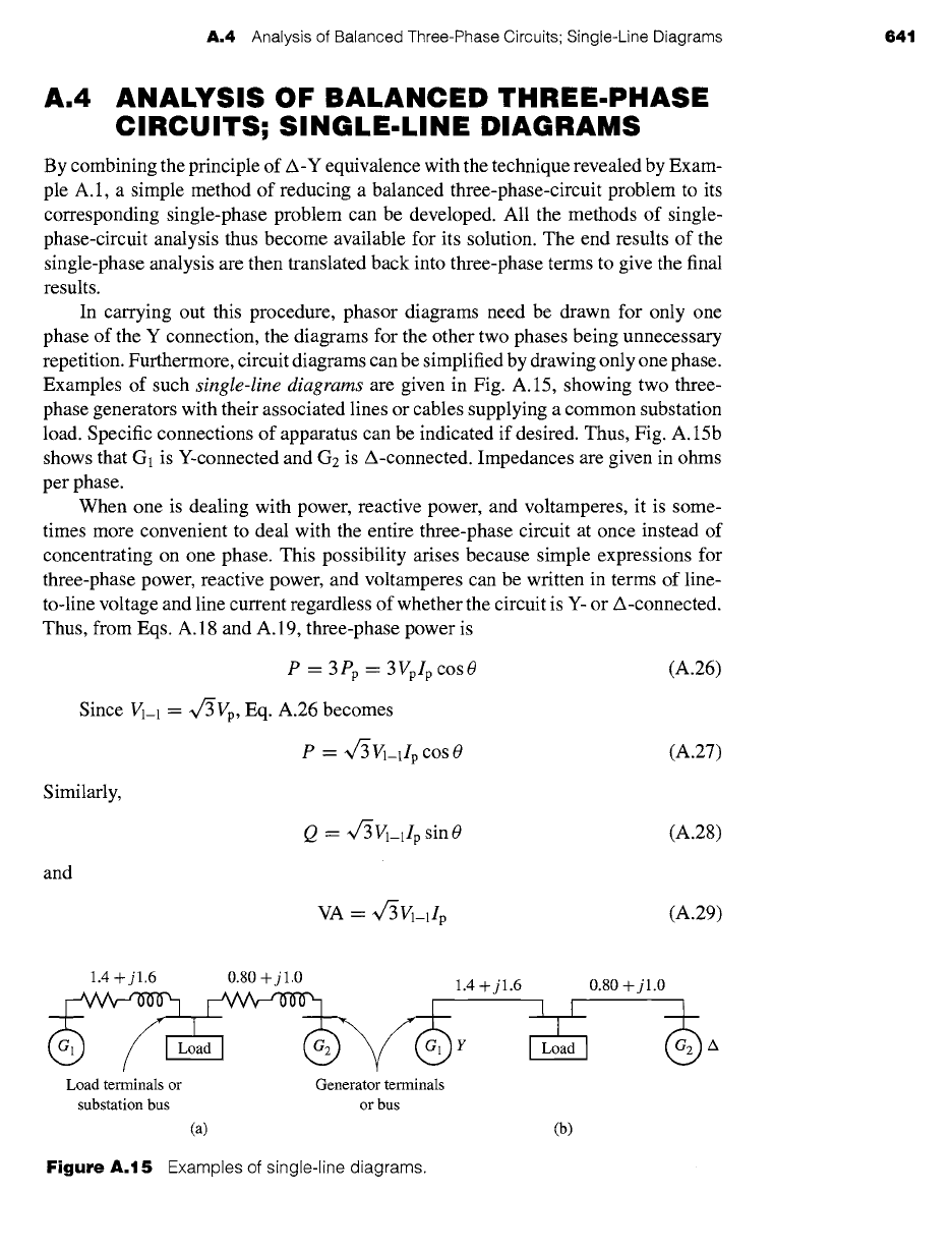
Examples of such
single-line diagrams
are given in Fig. A.15, showing two three-
phase generators with their associated lines or cables supplying a common substation
load. Specific connections of apparatus can be indicated if desired. Thus, Fig. A.15b
shows that G1 is Y-connected and G2 is A-connected. Impedances are given in ohms
per phase.
When one is dealing with power, reactive power, and voltamperes, it is some-
times more convenient to deal with the entire three-phase circuit at once instead of
concentrating on one phase. This possibility arises because simple expressions for
three-phase power, reactive power, and voltamperes can be written in terms of line-
to-line voltage and line current regardless of whether the circuit is Y- or A-connected.
Thus, from Eqs. A. 18 and A. 19, three-phase power is
P = 3Pp = 3VplpcosO
Since ~-1 = ~/3Vp, Eq. A.26 becomes
Similarly,
and
(A.26)
P = ~f3~-llp cos 0 (A.27)
Q = ~/-3Vl-llp sin 0 (A.28)
VA- ~/3Vl-llp (A.29)
1.4 + j 1.6 0.80 + j 1.0
~L2a
Load terminals or Generator terminals
substation bus or bus
(a)
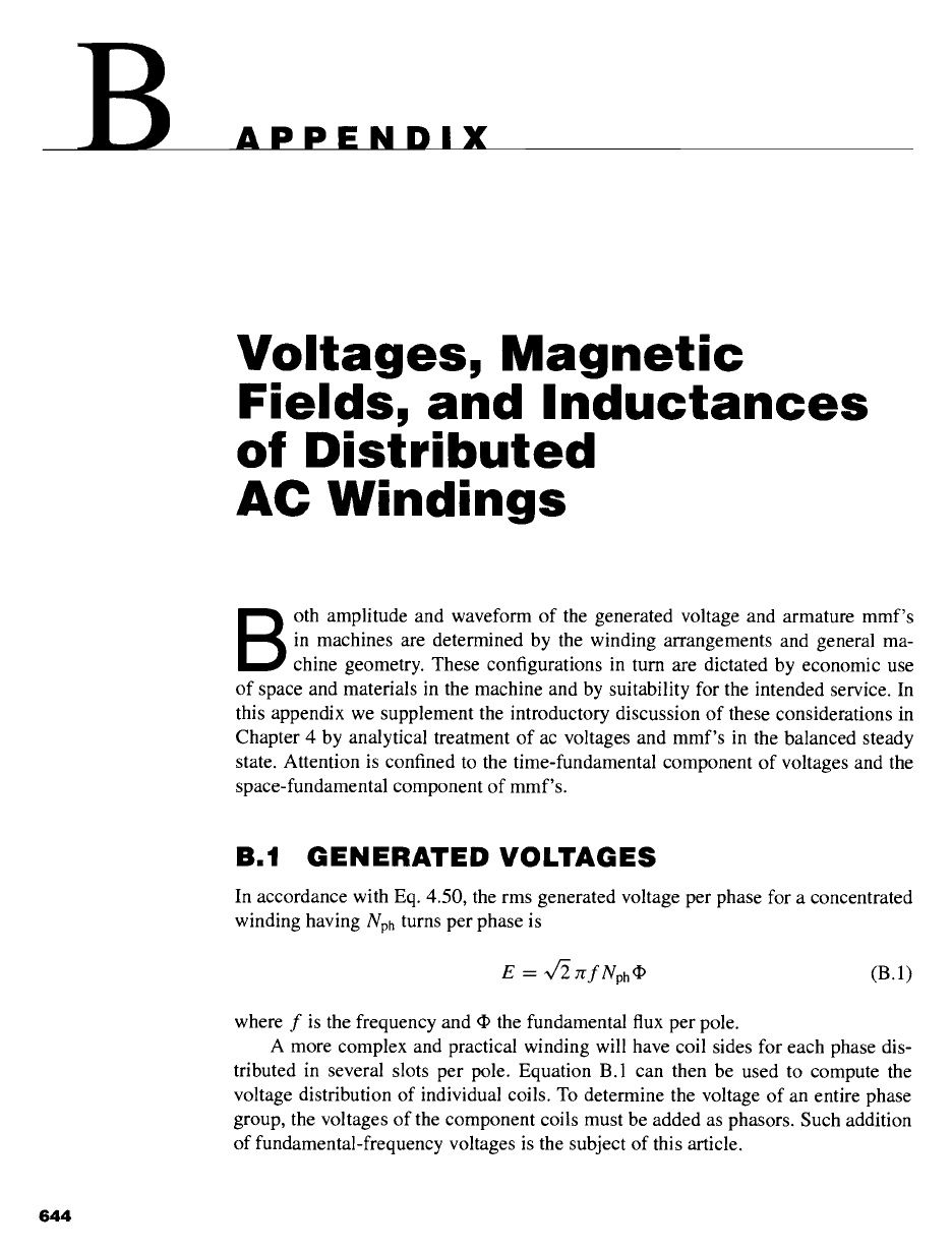
Figure A.15 Examples of
single-line diagrams.
1.4 + j 1.6 0.80 + j 1.0
r ILoad I
(b)
642 APPENDIX A Three-Phase Circuits
It should be borne in mind, however, that the power-factor angle 0, given by Eq. A.24,
is the angle between f'p and ip and not that between ~-1 and ip.
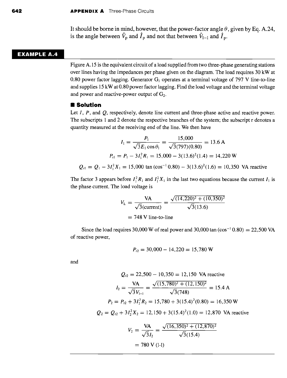
EXAMPLE A.4
Figure A. 15 is the equivalent circuit of a load supplied from two three-phase generating stations
over lines having the impedances per phase given on the diagram. The load requires 30 kW at
0.80 power factor lagging. Generator G1 operates at a terminal voltage of 797 V line-to-line
and supplies 15 kW at 0.80 power factor lagging. Find the load voltage and the terminal voltage
and power and reactive-power output of G2.
II Solution
Let I, P, and Q, respectively, denote line current and three-phase active and reactive power.
The subscripts 1 and 2 denote the respective branches of the system; the subscript r denotes a
quantity measured at the receiving end of the line. We then have
P] 15,000
-- = = 13.6A
11 -- ~/3E~ cos 01 ~/3(797)(0.80)
Pr~ -- P~ -- 31Z~R1
= 15,000- 3(13.6)2(1.4) = 14,220 W
Qrl = Q! - 312X~
= 15,000 tan (cos -~ 0.80) - 3(13.6)2(1.6) = 10,350 VA reactive
The factor 3 appears before I~ R~ and 12X, in the last two equations because the current 11 is
the phase current. The load voltage is
VA ~/(14,220) 2 + (10,350) 2
VL = --
~/C3(current) Vc3(13.6)
= 748 V line-to-line
Since the load requires 30,000 W of real power and 30,000 tan (cos-' 0.80) = 22,500 VA
of reactive power,
Pr2 "~
30,000 - 14,220 = 15,780 W
and
Qr2 =
22,500 - 10,350 -- 12,150 VA reactive
VA ~/(15,780) 2 + (12,150) 2
12 = ~/3VM ~/3(748) = 15.4 A
P2 = Pr2 4-
312R2
= 15,780 4- 3(15.4)2(0.80) = 16,350 W
Q2 = Qr2 4-
31~X2
= 12,150 + 3(15.4)2(1.0) = 12,870 VA reactive
VA ~/(16,350) z 4- (12,870) 2
V2 = =
431~ ,/3(15.4)
= 780 V (1-1)
A.5 Other Polyphase Systems 643
A.5 OTHER POLYPHASE SYSTEMS
Although three-phase systems are by far the most common of all polyphase systems,
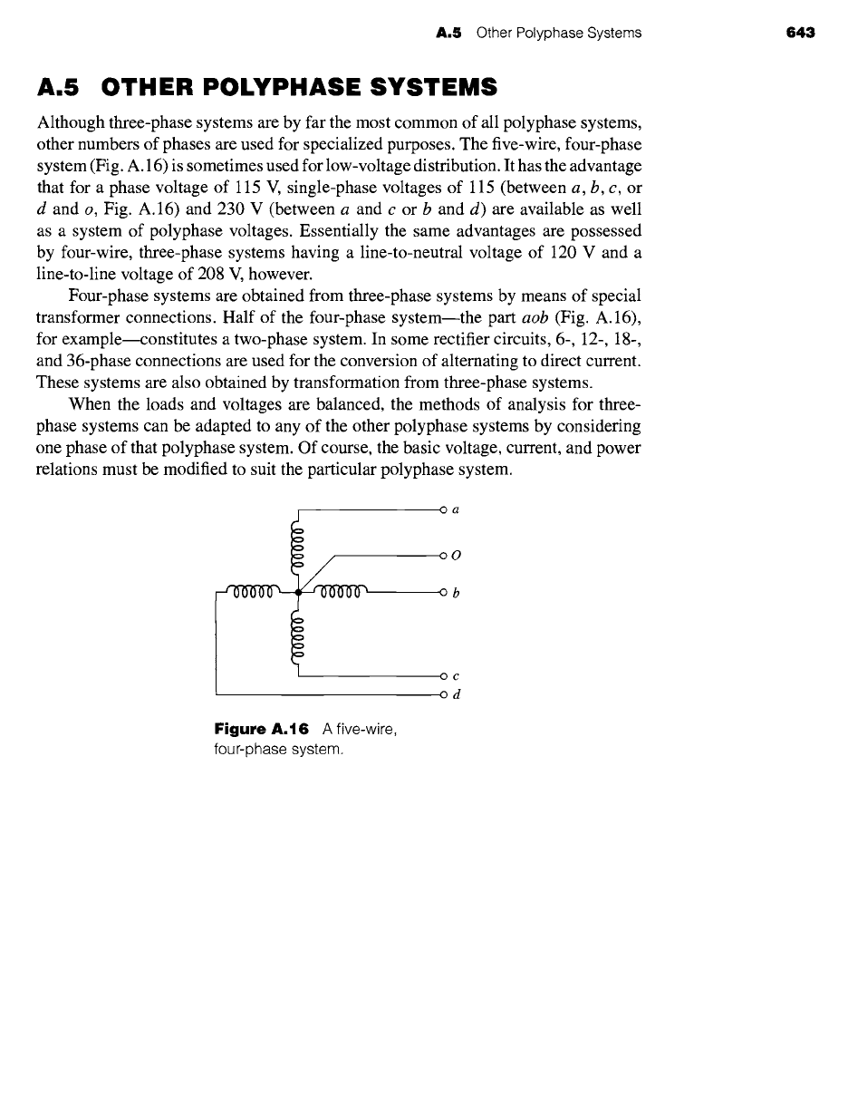
other numbers of phases are used for specialized purposes. The five-wire, four-phase
system (Fig. A. 16) is sometimes used for low-voltage distribution. It has the advantage
that for a phase voltage of 115 V, single-phase voltages of 115 (between a, b, c, or
d and o, Fig. A.16) and 230 V (between a and c or b and d) are available as well
as a system of polyphase voltages. Essentially the same advantages are possessed
by four-wire, three-phase systems having a line-to-neutral voltage of 120 V and a
line-to-line voltage of 208 V, however.
Four-phase systems are obtained from three-phase systems by means of special
transformer connections. Half of the four-phase system--the part aob (Fig. A.16),
for examplemconstitutes a two-phase system. In some rectifier circuits, 6-, 12-, 18-,
and 36-phase connections are used for the conversion of alternating to direct current.
These systems are also obtained by transformation from three-phase systems.
When the loads and voltages are balanced, the methods of analysis for three-
phase systems can be adapted to any of the other polyphase systems by considering
one phase of that polyphase system. Of course, the basic voltage, current, and power
relations must be modified to suit the particular polyphase system.
Oa
oO
ob
0¢
od
Figure A.16 A five-wire,
four-phase system.
Voltages, Magnetic
Fields, and Inductances
of Distributed
AC Windings
B
oth amplitude and waveform of the generated voltage and armature mmf's
in machines are determined by the winding arrangements and general ma-
chine geometry. These configurations in turn are dictated by economic use
of space and materials in the machine and by suitability for the intended service. In
this appendix we supplement the introductory discussion of these considerations in
Chapter 4 by analytical treatment of ac voltages and mmf's in the balanced steady
state. Attention is confined to the time-fundamental component of voltages and the
space-fundamental component of mmf's.
B.1 GENERATED VOLTAGES
In accordance with Eq. 4.50, the rms generated voltage per phase for a concentrated
winding having Nph turns per phase is
E = ~/2 ~fNph~
(B.1)
where f is the frequency and • the fundamental flux per pole.
A more complex and practical winding will have coil sides for each phase dis-
tributed in several slots per pole. Equation B.1 can then be used to compute the
voltage distribution of individual coils. To determine the voltage of an entire phase
group, the voltages of the component coils must be added as phasors. Such addition
of fundamental-frequency voltages is the subject of this article.
644
B.1 Generated Voltages 645
B.1.1 Distributed Fractional-Pitch Windings
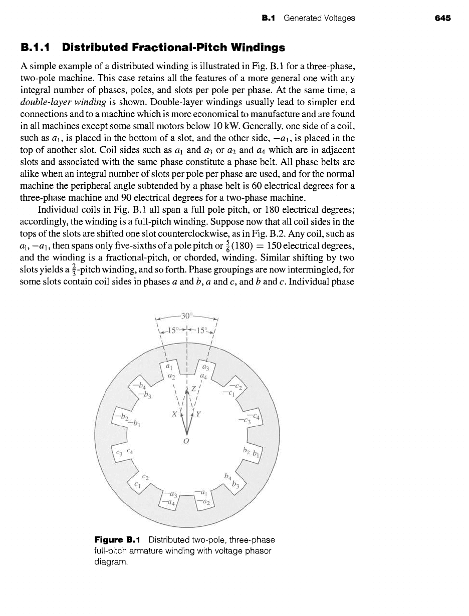
A simple example of a distributed winding is illustrated in Fig. B. 1 for a three-phase,
two-pole machine. This case retains all the features of a more general one with any
integral number of phases, poles, and slots per pole per phase. At the same time, a
double-layer winding
is shown. Double-layer windings usually lead to simpler end
connections and to a machine which is more economical to manufacture and are found
in all machines except some small motors below 10 kW. Generally, one side of a coil,
such as a l, is placed in the bottom of a slot, and the other side, -a], is placed in the
top of another slot. Coil sides such as al and a3 or
a2
and
a4
which are in adjacent
slots and associated with the same phase constitute a phase belt. All phase belts are
alike when an integral number of slots per pole per phase are used, and for the normal
machine the peripheral angle subtended by a phase belt is 60 electrical degrees for a
three-phase machine and 90 electrical degrees for a two-phase machine.
Individual coils in Fig. B.1 all span a full pole pitch, or 180 electrical degrees;
accordingly, the winding is a full-pitch winding. Suppose now that all coil sides in the
tops of the slots are shifted one slot counterclockwise, as in Fig. B.2. Any coil, such as
al, -a 1, then spans only five-sixths of a pole pitch or ~ (180) - 150 electrical degrees,
and the winding is a fractional-pitch, or chorded, winding. Similar shifting by two
2
slots yields a 5-pitch winding, and so forth. Phase groupings are now intermingled, for
some slots contain coil sides in phases a and b, a and c, and b and c. Individual phase
~...._--- 3 0o---_......~
~--15° i-~ 15°~/
\ I /
' /
[iiiiiiiiiiii!iliiiiiiiii!i!i~ .....
iiiiJ!JiiJ!ii!i!Ji!i!i!!!!iiiiiiiiiiiiiiiiiiii!iiiiiii!i ...........
li!iiiiii!iiiii!iiii!iiii~i~iiiiiiiiiiiii~iiiiiiiiiii!i!iiiii!!iiiiiiiii!i~ ....
iiiiiiiiiiiii!iiiiiiiii~ ~ ......................... iiiiiiiiiiiiii!ilili!i!iii!!ii!iii!~ .....
ii!i!i!i!i!iiiiiiii!i ~'~ `~iiiiii~i~ii~iii~i~!~i~i~ii!i!~!~i~!i!~!ii!!~ii!i!ii!!!~!!!i!!!i~iiii!ii!iii!i!i!~ ........
:~:~:~:~:~:::~: ;~iiii~i!i~i~i~i~i~i~!!~i~i~i!~i!~i~i~i~iiiii!iii!~i~iiiii~i~iii~ii~ii~ii~iiiii~iii~i~ii~ ....
I , :'~iiiiiiiiiiiiiiiiiiiiiiiiii!iliiii~ .................. ~iiiiiiiiiiiiiiiiiiii!iii!iiiiiiiiii!iiiiiiii;;~ ......
/ ,~iiii!iiiili!i!i!iii!i!iiiii!iiii!iiiiiii!iiii
/ ::~iiiiiiiiiii:iiiiiiiiii!!!iiiiiiiiii!iiiiiiiiiii!iiiiiiiiiiiiiiiii ..............................
)
" ,i,i,i,i,i,i,i,i,i,i,i,iiiiiiii! i ,, c c4
~~C2 be
..... '~!ii!iii!iiiiiiiiiiiiili!i .... c~ b3 .iiiiii)iiiiili!iiii~'~::
...... i:iiiiii i iiiii!iiil ............................................................... --a 3 --al ............................................................ iiiii!ii?!ii i iiiiiiiiiiiiii ......
........ ~i!iiiiii iiii!iiiiiii!iiiiiiiiiiiiiii~:-a4 -a2 "~i iiiiiii!iiiiiiiii!il iiiiii!iiiiii~ ........
Figure
B.1 Distributed two-pole, three-phase
full-pitch armature winding with voltage phasor
diagram.