Fitzgerald A.E. Electric Machinery
Подождите немного. Документ загружается.

646 APPENDIX B Voltages, Magnetic Fields, and Inductances of Distributed AC Windings
C 4 b4
......................................... C2 --a 1
~!~iii ~:i~iiiii~iii~iiiiiiii!iiiiiii~iiiiiiii~ii::
,~ :!:i ¸ ~:~!i~iii~ii~iii~i~i~ii~ii~i!iii~iii~iiiiii!i~i~iiii~i~iiiiiiiii~i~i~i!i!i!ii~
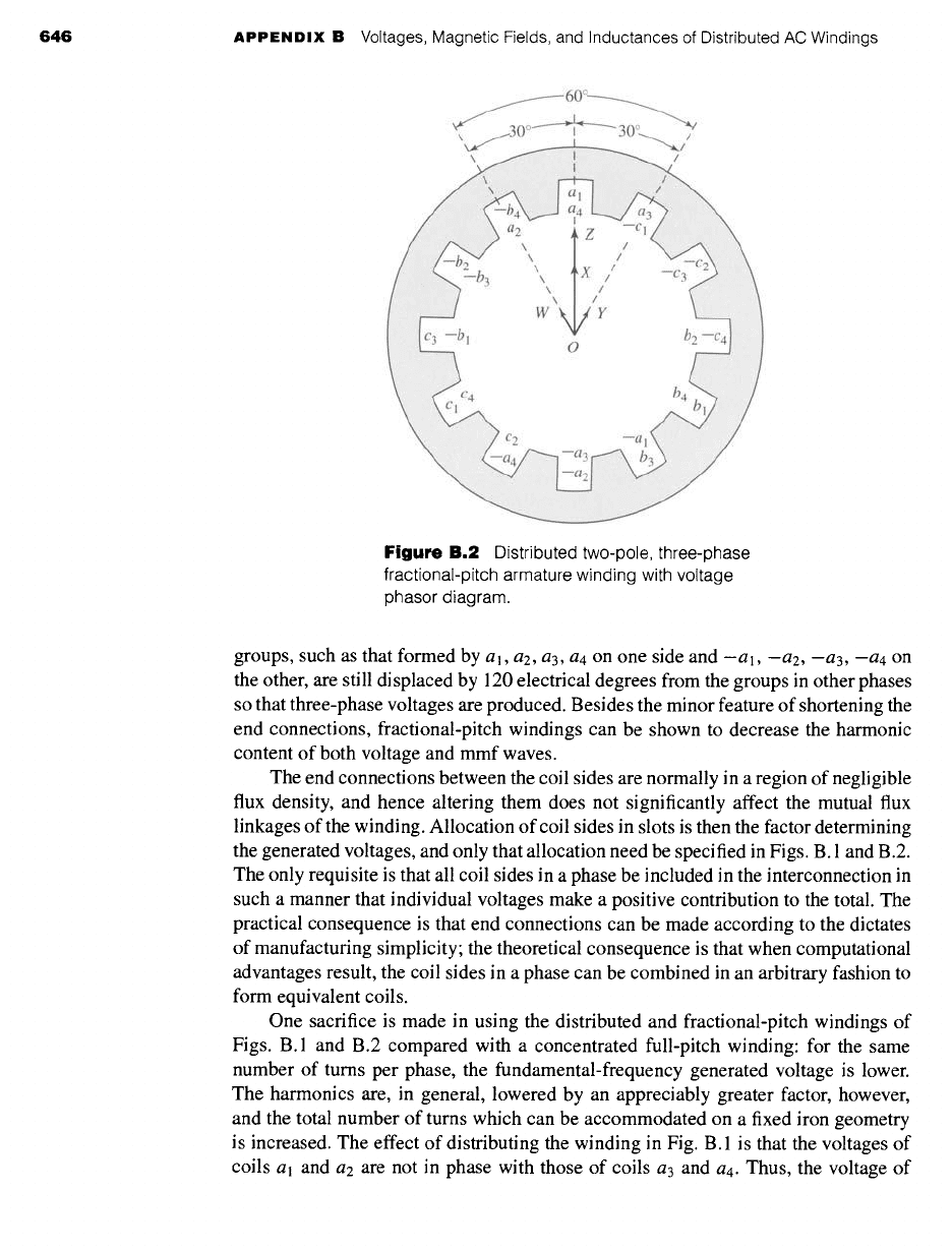
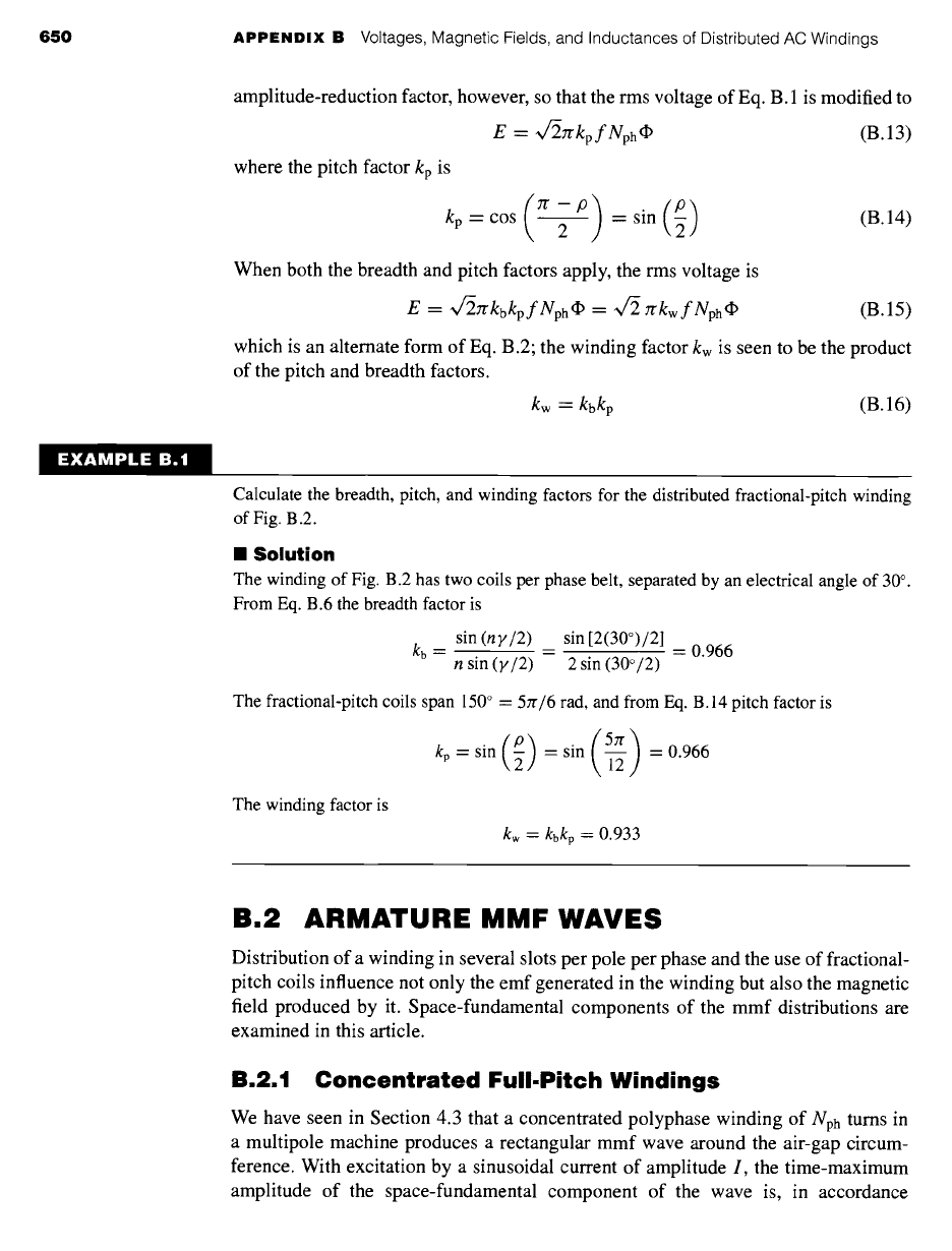
Figure B.2
Distributed two-pole, three-phase
fractional-pitch armature winding with voltage
phasor diagram.
groups, such as that formed by a l, a2, a3, a4 on one side and -a l, -ae, -a3, -a4 on
the other, are still displaced by 120 electrical degrees from the groups in other phases
so that three-phase voltages are produced. Besides the minor feature of shortening the
end connections, fractional-pitch windings can be shown to decrease the harmonic
content of both voltage and mmf waves.
The end connections between the coil sides are normally in a region of negligible
flux density, and hence altering them does not significantly affect the mutual flux
linkages of the winding. Allocation of coil sides in slots is then the factor determining
the generated voltages, and only that allocation need be specified in Figs. B. 1 and B.2.
The only requisite is that all coil sides in a phase be included in the interconnection in
such a manner that individual voltages make a positive contribution to the total. The
practical consequence is that end connections can be made according to the dictates
of manufacturing simplicity; the theoretical consequence is that when computational
advantages result, the coil sides in a phase can be combined in an arbitrary fashion to
form equivalent coils.
One sacrifice is made in using the distributed and fractional-pitch windings of
Figs. B.1 and B.2 compared with a concentrated full-pitch winding: for the same
number of turns per phase, the fundamental-frequency generated voltage is lower.
The harmonics are, in general, lowered by an appreciably greater factor, however,
and the total number of turns which can be accommodated on a fixed iron geometry
is increased. The effect of distributing the winding in Fig. B. 1 is that the voltages of
coils al and a2 are not in phase with those of coils a3 and a4. Thus, the voltage of
B.1 Generated Voltages 647
coils
al
and
a2
can be represented by phasor O X in Fig. B. 1, and that of coils
a3
and
a4 by the phasor O Y. The time-phase displacement between these two voltages is the
same as the electrical angle between adjacent slots, so that O X and O Y coincide with
the centerlines of adjacent slots. The resultant phasor O Z for phase a is obviously
smaller than the arithmetic sum of O X and O Y.
In addition, the effect of fractional pitch in Fig. B.2 is that a coil links a smaller
portion of the total pole flux than if it were a full-pitch coil. The effect can be super-
imposed on that of distributing the winding by regarding coil sides a2 and -al as an
equivalent coil with the phasor voltage O W (Fig. B.2), coil sides al, a4, -a2, and
-a3 as two equivalent coils with the phasor voltage O X (twice the length of O W),
and coil sides a3 and -a4 as an equivalent coil with phasor voltage O Y. The resultant
phasor O Z for phase a is obviously smaller than the arithmetic sum of O W, O X,
and O Y and is also smaller than O Z in Fig. B. 1.
The combination of these two effects can be included in a winding factor kw to
be used as a reduction factor in Eq. B. 1. Thus, the generated voltage per phase is
E -- v/2yr kw f Nph ¢P (B.2)
where
Nph
is the total turns in series per phase and kw accounts for the departure
from the concentrated full-pitch case. For a three-phase machine, Eq. B.2 yields the
line-to-line voltage for a A-connected winding and the line-to-neutral voltage for a
Y-connected winding. As in any balanced Y connection, the line-to-line voltage of
the latter winding is ~/3 times the line-to-neutral voltage.
B.1.2 Breadth and Pitch Factors
By separately considering the effects of distributing and of chording the winding,
reduction factors can be obtained in generalized form convenient for quantitative
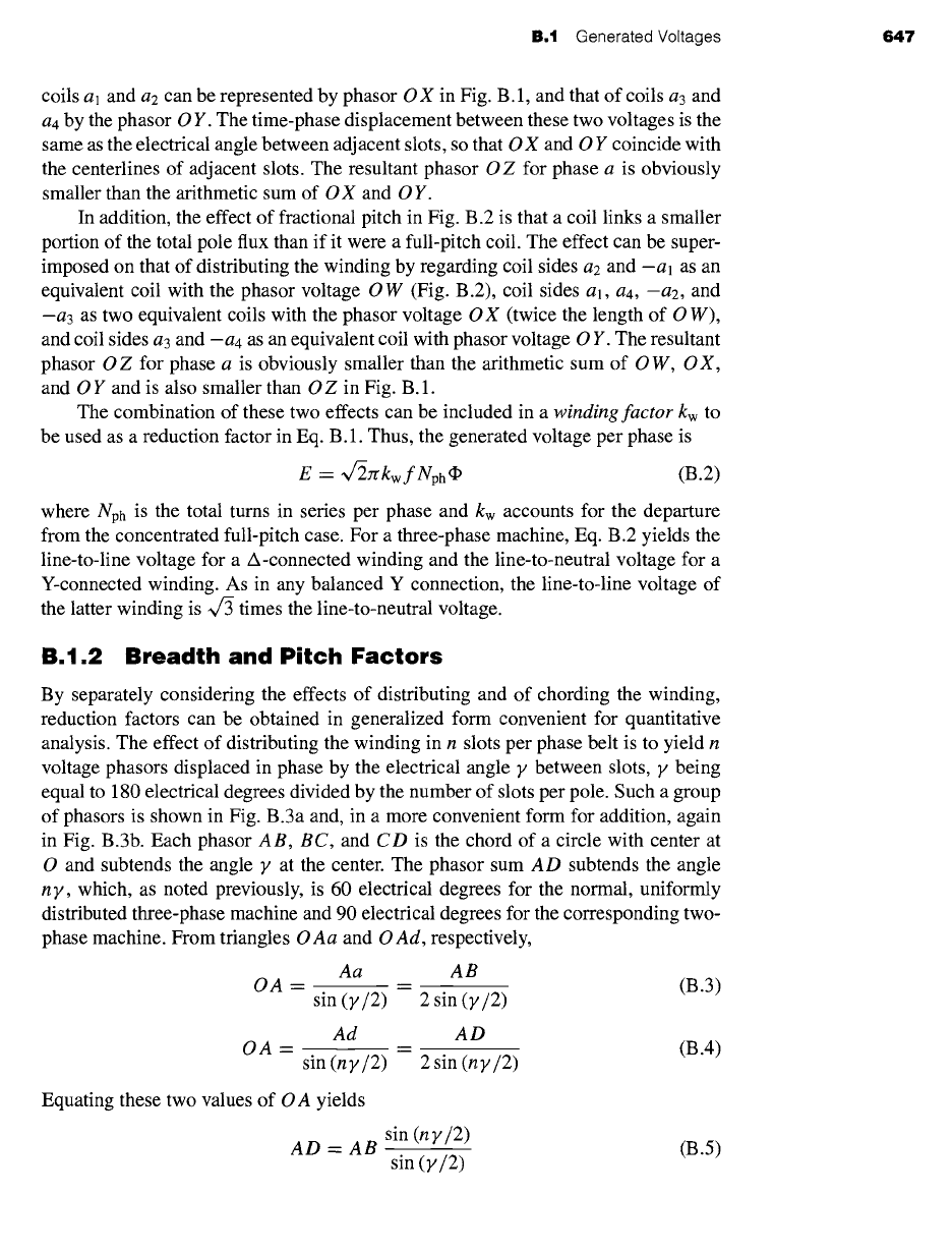
analysis. The effect of distributing the winding in n slots per phase belt is to yield n
voltage phasors displaced in phase by the electrical angle y between slots, 9/being
equal to 180 electrical degrees divided by the number of slots per pole. Such a group
of phasors is shown in Fig. B.3a and, in a more convenient form for addition, again
in Fig. B.3b. Each phasor AB, BC, and CD is the chord of a circle with center at
O and subtends the angle y at the center. The phasor sum AD subtends the angle
n y, which, as noted previously, is 60 electrical degrees for the normal, uniformly
distributed three-phase machine and 90 electrical degrees for the corresponding two-
phase machine. From triangles O Aa and O Ad, respectively,
Aa AB
oa = = (B.3)
sin (y/2) 2 sin (y/2)
Ad AD
OA -- = (B.4)
sin (ny/2) 2sin (ny/2)
Equating these two values of O A yields
AD = AB
sin (ny/2)
sin (y/2)
(B.5)
648 APPENDIX B Voltages, Magnetic Fields, and Inductances of Distributed AC Windings
/
/
B 11tt/~ y
J,f " ......
,' Iy
A (J ~' ", d l/l/ ~'~,, D
", '\ '~ I / ,~
\\
\, ~ i /
//
x\ \~
I
I
//
\\\ I /
(a) (b) \~l///
0
Figure
B.3 (a) Coil voltage phasors and (b) phasor sum.
But the arithmetic sum of the phasors is n(AB). Consequently, the reduction factor
arising from distributing the winding is
AD sin (ny/2)
kb -- = (B.6)
nAB n sin (y/2)
The factor kb is called the breadth factor of the winding.
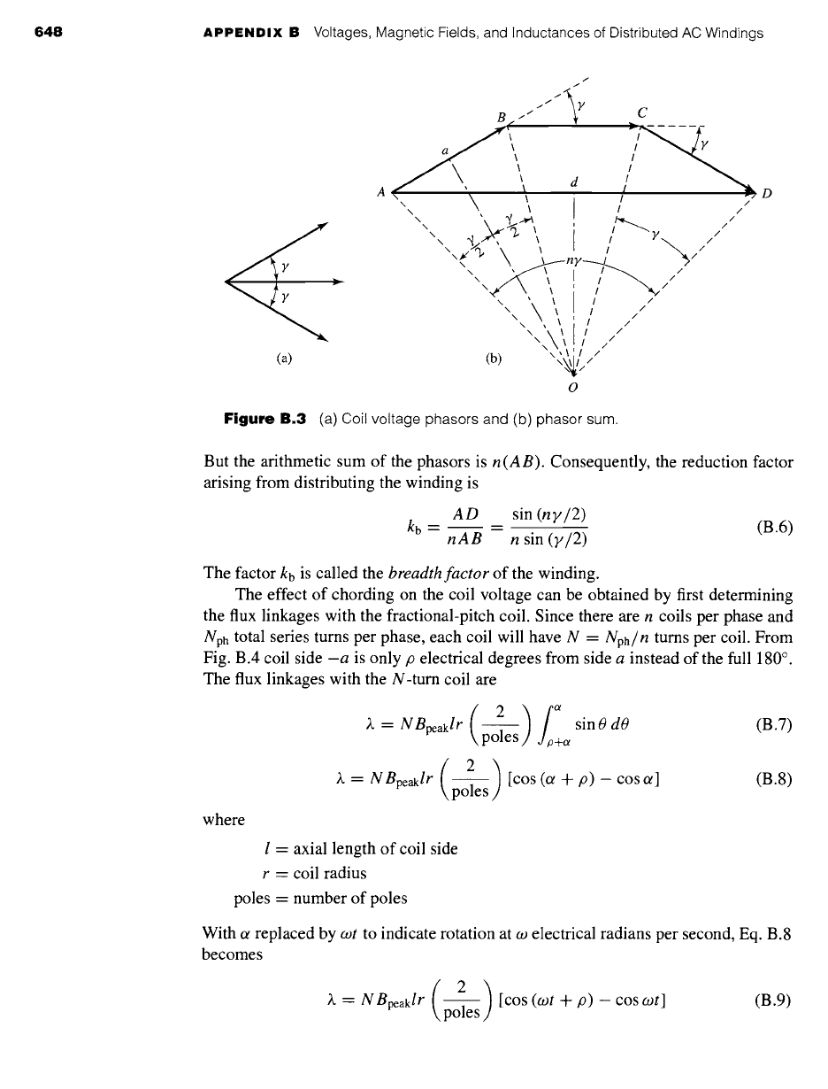
The effect of chording on the coil voltage can be obtained by first determining
the flux linkages with the fractional-pitch coil. Since there are n coils per phase and
Nph
total series turns per phase, each coil will have N
=
Nph/n turns per coil. From
Fig. B.4 coil side -a is only p electrical degrees from side a instead of the full 180 °.
The flux linkages with the N-turn coil are
)~ = N Bpeaklr sin 0 dO (B.7)
poles +~
)~ -- N
Bpeaklr
[COS (Or + p) -- COS Ct] (B.8)
poles
where
l = axial length of coil side
r = coil radius
poles - number of poles
With ot replaced by cot to indicate rotation at co electrical radians per second, Eq. B.8
becomes
2 ) [cos (cot +/9) - cos cot]
~ = NBpeaklr poles
(B.9)
B.1 Generated Voltages 649
0
Space distribution
I of flux density
B
=
Bpeak sin 0
a / N-turn coil
I I ,,~\1 24
/
/
]- p+et
~1
Figure B.4
Fractional-pitch coil
in
sinusoidal field.
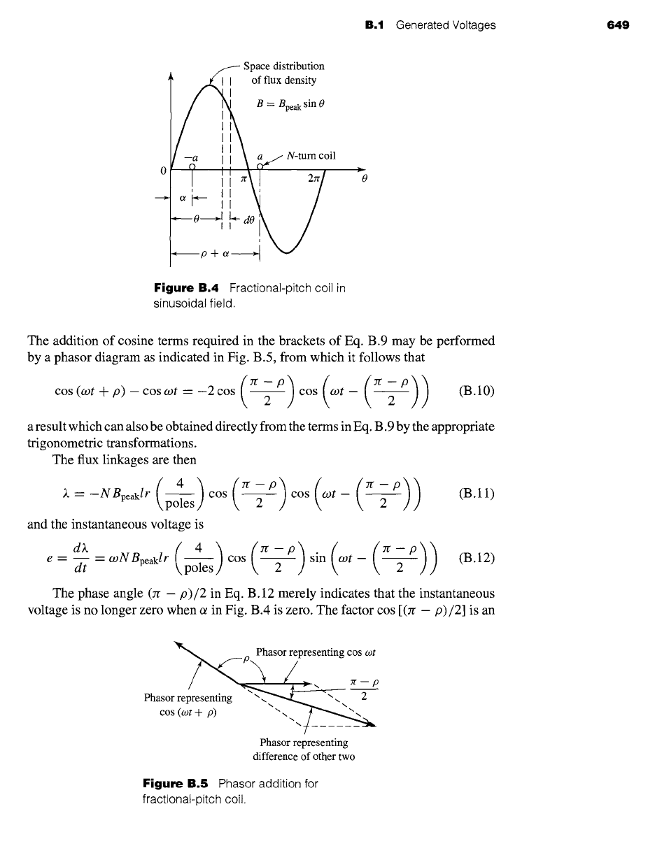
The addition of cosine terms required in the brackets of Eq. B.9 may be performed
by a phasor diagram as indicated in Fig. B.5, from which it follows that
cos (cot + p) - cos cot - -2 cos 2 cos cot - 2
a result which can also be obtained directly from the terms in Eq. B.9 by the appropriate
trigonometric transformations.
The flux linkages are then
( 4 ) (n-p) ((n-p)) (B.11)
k---NBpeaklr
poles cos 2 cos cot- 2
and the instantaneous voltage is
dX ( 4 ) (n-p) ((n-p))
e = dt - coNBpeaklr
cos sin cot - (B.12)
poles 2 2
The phase angle (n -
p)/2
in Eq. B.12 merely indicates that the instantaneous
voltage is no longer zero when ot in Fig. B.4 is zero. The factor cos [(n - p)/2] is an
~p Phasor representing cos cot
\/_
Phasor re;resenting ~. --~
cos +
...
/
Phasor representing
difference of other two
Figure
B.5 Phasor addition for
fractional-pitch coil.
650
APPENDIX B Voltages, Magnetic Fields, and Inductances of Distributed AC Windings
EXAMPLE B.1
amplitude-reduction factor, however, so that the rms voltage of Eq. B. 1 is modified to
E = v/27rkpfNph~
(B.13)
where the pitch factor kp is
(re-p) =sin(P ) (B.14)
kp = cos 2
When both the breadth and pitch factors apply, the rms voltage is
E = ~/27rkbkpfNph~ = ~/-2rrkwfNph~
(B.15)
which is an alternate form of Eq. B.2; the winding factor kw is seen to be the product
of the pitch and breadth factors.
kw -- kbkp
(B. 16)
Calculate the breadth, pitch, and winding factors for the distributed fractional-pitch winding
of Fig. B.2.
I
Solution
The winding of Fig. B.2 has two coils per phase belt, separated by an electrical angle of 30 °.
From Eq. B.6 the breadth factor is
sin
(ny/2)
sin [2(30°)/2]
kb = = = 0.966
n sin (y/2) 2 sin (30°/2)
The fractional-pitch coils span 150 ° = 5zr/6 rad, and from Eq. B.14 pitch factor is
kp=sin ~ =sin ~ =0.966
The winding factor is
kw = kbkp
= 0.933
B.2 ARMATURE MMF WAVES
Distribution of a winding in several slots per pole per phase and the use of fractional-
pitch coils influence not only the emf generated in the winding but also the magnetic
field produced by it. Space-fundamental components of the mmf distributions are
examined in this article.
B.2.1 Concentrated Full-Pitch Windings
We have seen in Section 4.3 that a concentrated polyphase winding of Nph turns in
a multipole machine produces a rectangular mmf wave around the air-gap circum-
ference. With excitation by a sinusoidal current of amplitude I, the time-maximum
amplitude of the space-fundamental component of the wave is, in accordance
B.2
Armature MMF Waves 651
with Eq. 4.6,
4 Nph
(Fagl)peak =
(~/2I) A. turns/pole (B.17)
rr poles
where the winding factor kw of Eq. 4.6 has been set equal to unity since in this case
we are discussing the mmf wave of a concentrated winding.
Each phase of a polyphase concentrated winding creates such a time-varying
standing mmf wave in space. This situation forms the basis of the analysis leading to
Eq. 4.39. For concentrated windings, Eq. 4.39 can be rewritten as
3 4 (Nph)(~/2I)cos (0ae- cot)= 6 (Nph)(~/2I)COS
(0ae-cot)
5r(0ae, t) = ~ ~- poles ~- poles
(B.18)
The amplitude of the resultant mmf wave in a three-phase machine in ampere-
turns per pole is then
6 ( Nph )
FA
= --
(~/2I) A. turns/pole (B.19)
Jr \poles
Similarly, for a nph-phase machine, the amplitude is
FA -- 2nph ( Nph ) (~/~l) A"
poles
(B.20)
In Eqs. B.19 and B.20, I is the rms current per phase. The equations include
only the fundamental component of the actual distribution and apply to concentrated
full-pitch windings with balanced excitation.
B.2.2 Distributed Fractional-Pitch Winding
When the coils in each phase of a winding are distributed among several slots per
pole, the resultant space-fundamental mmf can be obtained by superposition from the
preceding simpler considerations for a concentrated winding. The effect of distribution
can be seen from Fig. B.6, which is a reproduction of the two-pole, three-phase, full-
pitch winding with two slots per pole per phase given in Fig. B.1. Coils al and a2, bl
and b2, and cl and c2 by themselves constitute the equivalent of a three-phase, two-
pole concentrated winding because they form three sets of coils excited by polyphase
currents and mechanically displaced 120 ° from each other. They therefore produce
a rotating space-fundamental mmf; the amplitude of this contribution is given by
Eq. B.19 when Nph is taken as the sum of the series turns in coils al and a2 only.
Similarly, coils a3 and a4, b3 and b4, and c3 and
Ca
produce another identical mmf
wave, but one which is phase-displaced in space by the slot angle 9/from the former
wave. The resultant space-fundamental mmf wave for the winding can be obtained
by adding these two sinusoidal contributions.
The mmf contribution from the
ala2bl b2clc2
coils can be represented by the pha-
sor O X in Fig. B.6. Such phasor representation is appropriate because the waveforms
concerned are sinusoidal, and phasor diagrams are simply convenient means for
652 APPENDIX B Voltages, Magnetic Fields, and Inductances of Distributed AC Windings
c 3 c4
mc 1
C2 b 4
.... _a4 .... --a 2
--C
30 °
/
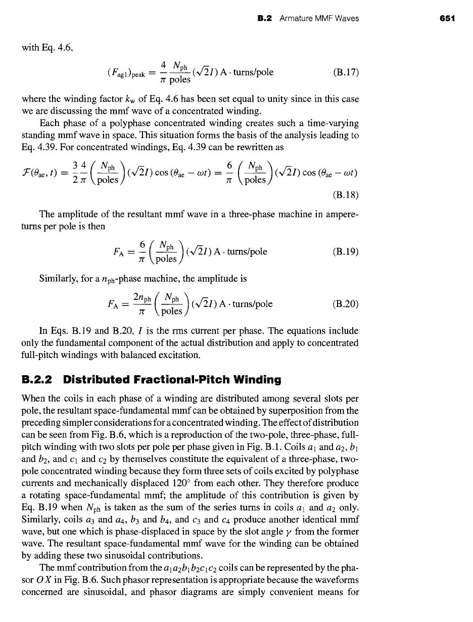
Figure B.6
Distributed two-pole, three-phase, full-pitch
armature winding with mmf phasor diagram.
adding sine waves. These are space sinusoids, however, not time sinusoids. Pha-
sor O X is drawn in the space position of the mmf peak for an instant of time when the
current in phase a is a maximum. The length of O X is proportional to the number of
turns in the associated coils. Similarly, the mmf contribution from the
a3a4b3b4c3c4
coils may be represented by the phasor O Y. Accordingly, the phasor O Z represents
the resultant mmf wave. Just as in the corresponding voltage diagram, the resultant
mmf is seen to be smaller than if the same number of turns per phase were concentrated
in one slot per pole.
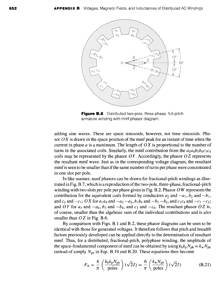
In like manner, mmf phasors can be drawn for fractional-pitch windings as illus-
trated in Fig. B.7, which is a reproduction of the two-pole, three-phase, fractional-pitch
winding with two slots per pole per phase given in Fig. B.2. Phasor O W represents the
contribution for the equivalent coils formed by conductors a2 and -al, b2 and -bl,
and
C2
and -cl;
OX
for
ala4
and -a3 -a2,
b]b4
and -b3 -b2, and
¢1C4
and -c3 -c2;
and O Y for a3 and
--a4,
b3 and
-b4,
and c3 and -c4. The resultant phasor OZ is,
of course, smaller than the algebraic sum of the individual contributions and is also
smaller than O Z in Fig. B.6.
By comparison with Figs. B. 1 and B.2, these phasor diagrams can be seen to be
identical with those for generated voltages. It therefore follows that pitch and breadth
factors previously developed can be applied directly to the determination of resultant
mmf. Thus, for a distributed, fractional-pitch, polyphase winding, the amplitude of
the space-fundamental component of mmf can be obtained by using
kbkpNph
= kw Nph
instead of simply Nph in Eqs. B. 19 and B.20. These equations then become
6 (kbkpNph)
FA -- -- (~/21)
Jr poles
- 6__ ( kwNph ) (~f21)
Jr poles
(B.21)
B.3 Air-Gap Inductances of Distributed Windings 653
c 3 --b 1
a2
// , 60 °
W // b:~
Y ---" b4 bl :ii~iiill
--a 1
--a3~
Figure B.7 Distributed two-pole, three-phase,
fractional-pitch armature winding with mmf
phasor diagram.
for a three-phase machine and
FA- 2nphzr
(kbkpNph)poles
(~/2I).__ 2nphg (kwNph)poles (~//2I)
for a nph-phase machine, where FA is in ampere-turns per pole.
(B.22)
B.3 AIR-GAP INDUCTANCES
OF DISTRIBUTED WINDINGS
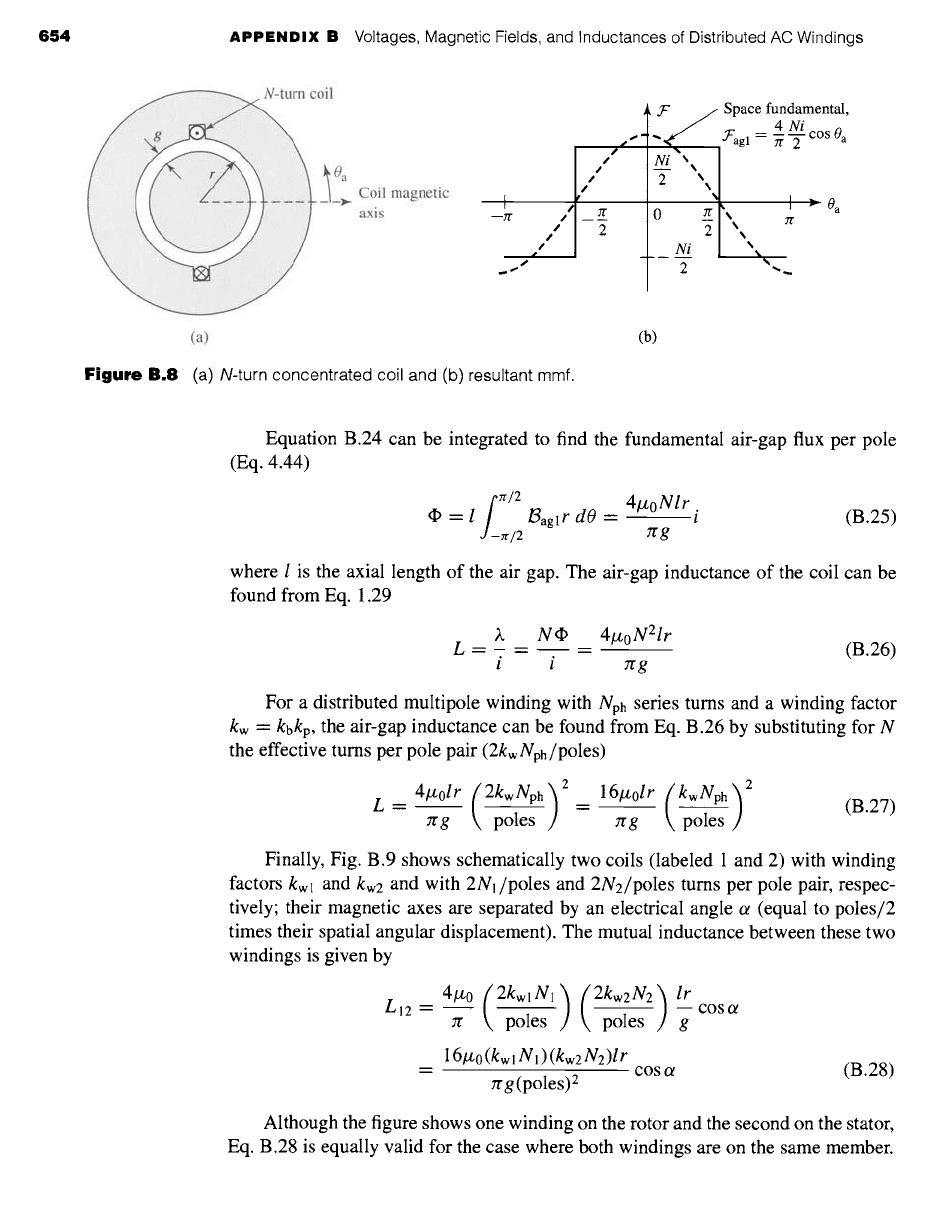
Figure B.8a shows an N-turn, full-pitch, concentrated armature winding in a two-pole
magnetic structure with a concentric cylindrical rotor. The mmf of this configuration
is shown in Fig. B.8b. Since the air-gap length g is much smaller than the average
air-gap radius r, the air-gap radial magnetic field can be considered uniform and
equal to the mmf divided by g. From Eq. 4.3 the space-fundamental mmf is given
by
4 Ni
• ~"agl -" -- ~ COS 0a
(B.23)
7r 2
and the corresponding air-gap flux density is
~agl
J~agl -- /L0
g
21zoN i
rcg
COS 0a
(B.24)
654
APPENDIX B Voltages, Magnetic Fields, and Inductances of Distributed AC Windings
oil
l a Coil magnetic
-~
I
axis --zr
I
.T" / Space fundamental,
4Ni
Sf ~
"~'agl =
7r 2
cos 0 a
/ °
¢ %
"
S %
(a)
Figure
B.8 (a) N-turn concentrated coil and (b) resultant mmf.
(b)
Equation B.24 can be integrated to find the fundamental air-gap flux per pole
(Eq. 4.44)
rr/2
= l
~aglr
dO =
J -rr/2
41zoNlr .
~t (B.25)
7rg
where I is the axial length of the air gap. The air-gap inductance of the coil can be
found from Eq. 1.29
)~ N ~ 4lzoN2lr
L = - = = (B.26)
i i rrg
For a distributed multipole winding with Nph series turns and a winding factor
kw -- kbkp,
the air-gap inductance can be found from Eq. B.26 by substituting for N
the effective turns per pole pair (2kw Nph/poles)
L=
41zolr
(2kwNph) 2 _
16#0/r (kwNph) 2
rrg poles -- rrg poles (B.27)
Finally, Fig. B.9 shows schematically two coils (labeled 1 and 2) with winding
factors kwl and kw2 and with 2N1/poles and 2N2/poles turns per pole pair, respec-
tively; their magnetic axes are separated by an electrical angle ot (equal to poles/2
times their spatial angular displacement). The mutual inductance between these two
windings is given by
,o.es c°s°
16/z0 (kw I N! )(kw2
N2)lr
= cosct (B.28)
:rrg (poles) 2
Although the figure shows one winding on the rotor and the second on the stator,
Eq. B.28 is equally valid for the case where both windings are on the same member.
B.3
Air-Gap Inductances of Distributed Windings 655
Figure B.9
Two distributed windings
separated by electrical angle o~.
The two-pole stator-winding distribution of Fig. B.2 is found on an induction motor with an
air-gap length of 0.381 mm, an average rotor radius of 6.35 cm, and an axial length of 20.3 cm.
Each stator coil has 15 turns, and the coil phase connections are as shown in Fig. B. 10. Calculate
the phase-a air-gap inductance
Laa0
and the phase-a to phase-b mutual inductance Lab.
II
Solution
Note that the placement of the coils around the stator is such that the flux linkages of each of
the two parallel paths are equal. In addition, the air-gap flux distribution is unchanged if, rather
than dividing equally between the two legs, as actually occurs, one path were disconnected and
all the current were to flow in the remaining path. Thus, the phase inductances can be found
by calculating the inductances associated with only one of the parallel paths.
This result may appear to be somewhat puzzling because the two paths are connected in
parallel, and thus it would appear that the parallel inductance should be one-half that of the
single-path inductance. However, the inductances share a common magnetic circuit, and their
T T T
al a2 bl b2 cl c2
~a 1 ~a 2 ~b 1 ~b 2 ~c 1 ~c 2
a3 a4 b 3 b4 c3 c4
~a 3 ~b 3
a4 b4 ~c 3 c 4
Phase a Phase b Phase c
Figure
B.10 Coil phase connections of Fig. B.2 for Example B.2.
EXAMPLE B.2