Canale L.C.F., Mesquita R.A., Totten G.E. Failure Analysis of Heat Treated Steel Components
Подождите немного. Документ загружается.


Steel Heat Treatment Failures due to
Quenching
L.C.F. Canale, Universidade de Sa˜o Paulo
G.E. Totten, Associac¸a˜o Instituto Internacional de Cieˆncia and
Portland State University
QUENCHING is one of the more important
heat treating processes, because it is so closely
related to dimensional control requirements and
control of residual stresses. Quenching is often
attributed to many distortion and cracking pro-
blems, whether the quenching process is the
actual root cause or not. Approximately 20% of
the problems in heat treating relate to heating
processes, while as much as 80% of the pro-
blems relate to cooling processes. This chapter
provides an overview of the fundamental
material- and process-related parameters of
quenching on residual stress, distortion control,
and cracking. This overview is followed by
various selected case histories of failures
attributed to the quenching process.
Phase Transformations During Heating
and Quenching
Properties such as hardness, strength, duc-
tility, and toughness are dependent on the
microstructural products that are present in steel.
Typically, the first step in the transformation
process is to heat the steel to its austenitizing
temperature. The austenitized steel is then
cooled rapidly to avoid the formation of pearlite,
which is a relatively soft transformation product,
and to maximize formation of martensite, a
relatively hard transformation product, and to
achieve the desired as-quenched hardness.
The most common transformation products
that may be formed in quench-hardenable steels
from austenite are, in order of formation with
decreasing cooling rate, martensite, bainite,
pearlite, ferrite, and cementite. The formation of
these products and the proportions of each are
dependent on the time and temperature cooling
history of the particular alloy and the elemental
composition of that alloy. The transformation
products formed are typically illustrated with the
use of transformation diagrams that show the
temperature-time dependence of the micro-
structure formation process for the alloy being
studied. Two of the most commonly used trans-
formation diagrams are the time-temperature
transformation and continuous cooling trans-
formation diagrams.
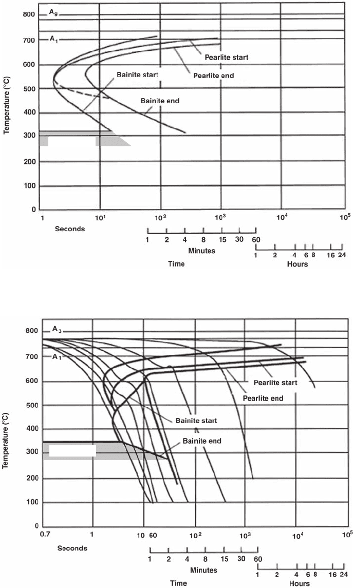
Time-temperature transformation (TTT)
diagrams, also called isothermal transforma-
tion diagrams, are developed by heating small
samples of steel to the austenite transformation
temperature, followed by rapid cooling to a tem-
perature intermediate between the austenitizing
and the martensite start (M
s
) temperature, and
then holding for a fixed period of time until the
transformation is complete, at which point the
transformation products are determined. This is
done repeatedly until a TTT diagram is con-
structed, such as that shown for an unalloyed
steel (AISI 1045) in Fig. 1 (Ref 1). The TTT
diagrams can only be read along the isotherms.
Continuous Cooling Transformation Dia-
grams. Alternatively, a given steel may be
continuously cooled from the austenitizing tem-
perature at different specified rates. The pro-
portion of transformation products formed after
cooling to various temperatures intermediate
between the austenitizing temperature and the
M
s
temperature is used to construct a continuous
cooling transformation (CCT) diagram, such as
the one shown for an unalloyed carbon steel
(AISI 1045) in Fig. 2 (Ref 1). The CCT curves
provide data on the temperatures for each phase
transformation, the amount of transformation
product obtained for a given cooling rate with
time, and the cooling rate necessary to obtain
martensite. The critical cooling rate is dictated
by the time required to avoid formation of
Name ///sr-nova/Dclabs_wip/Failure_Analysis/5113_255-284.pdf/Chap_08/ 18/8/2008 3:28PM Plate # 0 pg 255
Failure Analysis of Heat Treated Steel Components
L.C.F. Canale, R.A. Mesquita, and G.E. Totten, editors, p 255-284
DOI: 10.1361/faht2008p255
Copyright © 2008 ASM International®
All rights reserved.
www.asminternational.org
Martensite
Fig. 1
Time-temperature transformation diagram of an unalloyed steel containing 0.45% C. Austenitizing temperature: 880
C.
Source: Ref 1
Martensite
Fig. 2
Continuous cooling transformation diagram of an unalloyed steel containing 0.45% C. Austenitizing temperature: 880
C.
Source: Ref 1
256 / Failure Analysis of Heat Treated Steel Components
Name ///sr-nova/Dclabs_wip/Failure_Analysis/5113_255-284.pdf/Chap_08/ 18/8/2008 3:28PM Plate # 0 pg 256
pearlite for the particular steel being quenched.
As a general rule, a quenchant must produce a
cooling rate equivalent to or faster than that
indicated by the nose of the pearlite transfor-
mation curve to maximize the martensite trans-
formation product (Ref 1). The CCT diagrams
can only be read along the curves of different
cooling rates, and a continuous cooling curve
can only be superimposed on a CCT but not on a
TTT diagram.
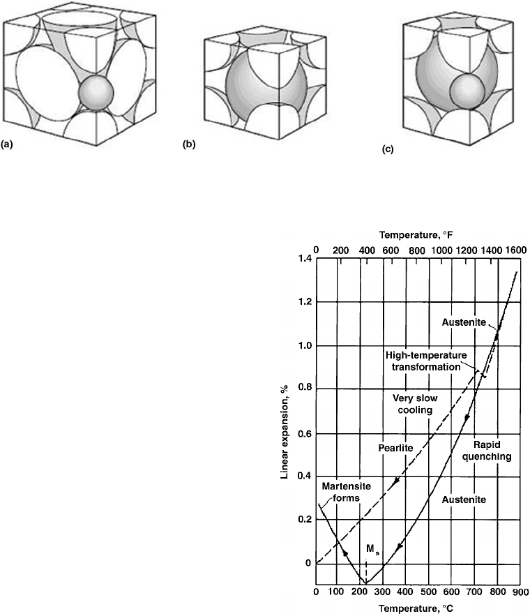
Metallurgical Crystal Structure. When
steel is slowly cooled, it undergoes a crystal
structure (size) change as it transforms from a
less densely packed (face-centered cubic) aus-
tenite to a more densely packed body-centered
cubic structure of ferrite. At faster cooling rates,
the formation of ferrite is suppressed, and mar-
tensite, which is an even less densely packed
body-centered tetragonal structure than auste-
nite, is formed. Illustrations of these crystal
structures are provided in Fig. 3 (Ref 1). This re-
sults in a volumetric expansion at the M
s
tem-
perature as shown in Fig. 4 (Ref 1).
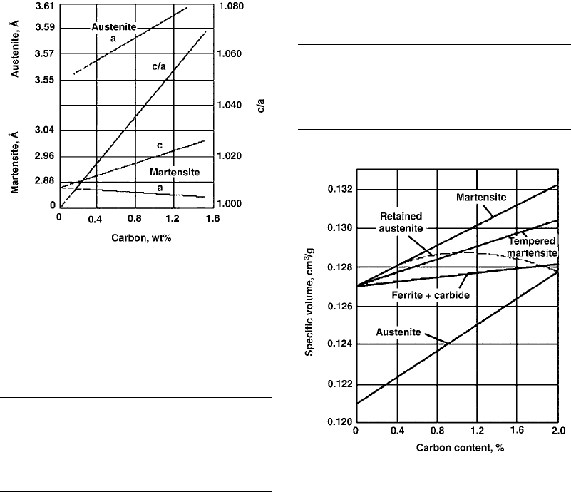
Figure 5 shows that the crystal lattice of aus-
tenite expands with increasing carbon content
(Ref 2). It has been reported that typically when
a carbide-ferrite mixture is converted to mar-
tensite, the resulting expansion due to increasing
carbon content is approximately 0.05 mm/mm
(0.002 in./in.) at 0.25% C and 0.18 mm/mm
(0.007 in./in.) at 1.2% C (Ref 2). The fractional
increase in size when austenite is converted
to martensite is approximately 0.36 mm/mm
(0.014 in./in.) for eutectoid compositions. This
illustrates the effect of carbon structure and steel
transformation on residual stresses and distor-
tion leading to dimensional changes.
Estimation of Volumetric Change due to
Steel Transformation upon Quenching.
Various microstructures are possible upon
quenching of steel, and the potential micro-
structural transformations that are possible for a
given steel are illustrated by their CCT or TTT
diagrams. Furthermore, dimensional changes de-
pend on carbon content and the microstructural
transformation product formed. Table 1 sum-
marizes the atomic volumes of various micro-
structural components as a function of carbon
content (Ref 3). Table 2 provides an estimate of
volumetric changes as a function of carbon
Fig. 3
Crystal structures. (a) Austenite, face-centered cubic. (b) Ferrite, body-centered cubic. (c) Martensite, body-centered tetra-
gonal. Source: Ref 1
Fig. 4
Steel expansion and contraction upon heating and
cooling. Source: Ref 1
Steel Heat Treatment Failures due to Quenching / 257
Name ///sr-nova/Dclabs_wip/Failure_Analysis/5113_255-284.pdf/Chap_08/ 18/8/2008 3:28PM Plate # 0 pg 257
content for various metallurgical transforma-
tions (Ref 4, 5).
Thelning reported that volumetric expansion
occurring as a result of quenching could be
estimated from (Ref 6):
DV=V · 100=(100 V
c
V
a
) · 1:68C
+V
a
( 4:64+2:21C)
(Eq 1)
where (DV/V) · 100 equals the percentage
change in volume, V
c
equals the percentage by
volume of undissolved cementite, (100V
c
V
a
) equals the percentage by volume of mar-
tensite, V
a
equals the percentage by volume of
austenite, and C equals the percentage by weight
of carbon dissolved in austenite and martensite.
Berns reported that if the value of (DV/V)is
known or can be computed, internal stresses
that are developed in a part due to tempera-
ture differences (DT) arising from either
one-dimensional heating or cooling could be
estimated from (Ref 7):
s=E e=E
1
/
3
(DV=V)=E a DT (Eq 2)
where E (modulus of elasticity) = 2 · 10
5
N/mm
2
and a (coefficient of thermal expan-
sion) = 1.2 · 10
5
. Relative volume changes
due to phase transformation are illustrated in
Fig. 6 (Ref 7).
Kunitake and Susigawa (Ref 8) reported that
the tendency for cracking decreases as the start
of the martensite transformation temperature
(M
s
) increases. The M
s
temperature was ap-
proximated from:
M
s
(
C)=521 353C 225Si 24:3Mn
27:4Ni 17:7Cr 25: 8Mo
(Eq 3)
The correlation between the occurrence of
quench cracks and M
s
temperature is shown
in Fig. 7. A similar study produced a poor
Fig. 5
Carbon content versus lattice parameters of (retained)
austenite and martensite at room temperature. “a”at
the top of the graph is the lattice parameter of face-centered cubic
austenite. a and c in the lower half of the graph are the two lattice
parameters of tetragonal martensite. The ratio of c/a for martensite
as a function of carbon content is also given. Source: Ref 2
Table 1 Atomic volume of various
microstructural constituents of ferrous alloys
Phase Apparent atomic volume, A
˚
3
Ferrite 11.789
Cementite 12.769
Ferrite+carbides 11.786+0.163 C(a)
Pearlite 11.916
Austenite 11.401+0.329 C(a)
Martensite 11.789+0.370 C(a)
(a) Percent carbon. Source: Ref 3
Table 2 Volumetric changes with various steel
transformations
Steel transformation Volumetric change
Pearlite?austenite 4.64+2.21 C(a)
Austenite?martensite 4.640.53 C(a)
Austenite?acicular lower bainite 4.641.43 C(a)
Austenite?feathered upper bainite 4.642.21 C(a)
(a) Percent carbon. Source: Ref 4, 5
Fig. 6
Specific volume (DV/V) of carbon steels relative to
room temperature. Source: Ref 7
258 / Failure Analysis of Heat Treated Steel Components
Name ///sr-nova/Dclabs_wip/Failure_Analysis/5113_255-284.pdf/Chap_08/ 18/8/2008 3:28PM Plate # 0 pg 258
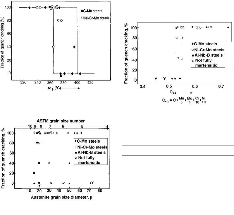
correlation between grain size and quench
cracking, as shown in Fig. 8 (Ref 8).
Kunitake and Sisigawa (Ref 8) developed a
relationship to interrelate the combined effect
of both carbon content and elemental composi-
tion on cracking propensity. This was designated
as the carbon equivalent (C
eq
), and it is calcu-
lated by:
C
eq
=C+Mn=5+Mo=5+Cr=10+Ni=10 (Eq 4)
Figure 9 shows a good correlation between
the carbon equivalent and steel cracking. In
general, steels are classified as crack sensitive
if the C
eq
value is greater than 0.52 to 0.55%
(Ref 8).
Another measure of cracking tendency is the
difference in the start and finish temperatures
of martensite formation (M
s
M
f
) (Ref 9).
A summary of the M
s
and M
f
values for some
common steels is provided in Table 3.
The correlation between cracking sensitivity
and the transformation temperature range is due
in part to the low M
f
caused by high-carbon steels
(which expand more) and to the fact that wide
transformation ranges may result in cracking of
the brittle untempered martensite formed at
higher temperatures in the transformation range.
Fujio et al. (Ref 10) showed that the vol-
umetric expansion caused by martensite for-
mation can be estimated from the maximum
cooling rate in a particular type of steel, as
shown in Fig. 10. Similar correlations were
evaluated for both cooling time and cooling rate
at the M
s
temperature. However, these correla-
tions were dependent on the cross-sectional
size and thus could not be used for gears or
other parts with complex shapes. Volumetric
expansion can be estimated for various cross-
sectional sizes by a correlation between the
volume fraction of martensite versus the cooling
Fig. 7
Relationship between quench cracking frequency and
martensite start (M
s
) temperature. Source: Ref 8
Fig. 8
Relationship between quench cracking frequency and
austenitic grain size. Source: Ref 8
Fig. 9
Relationship between carbon equivalent (C
eq
) and
quench cracking frequency. Source: Ref 8
Table 3 Martensite start (M
s
) and martensite
finish (M
f
) values for selected steels
AISI No.
Austenitizing
temperature, °CM
s
, °CM
f
, °C
1065 815 275 150
1090 885 215 80
1335 845 340 230
3140 845 330 225
4130 870 375 290
4140 845 340 220
4340 845 290 165
4640 845 340 255
5140 845 330 240
8630 870 365 280
8695 845 135 ...
9442 860 325 15
Steel Heat Treatment Failures due to Quenching / 259
Name ///sr-nova/Dclabs_wip/Failure_Analysis/5113_255-284.pdf/Chap_08/ 18/8/2008 3:28PM Plate # 0 pg 259
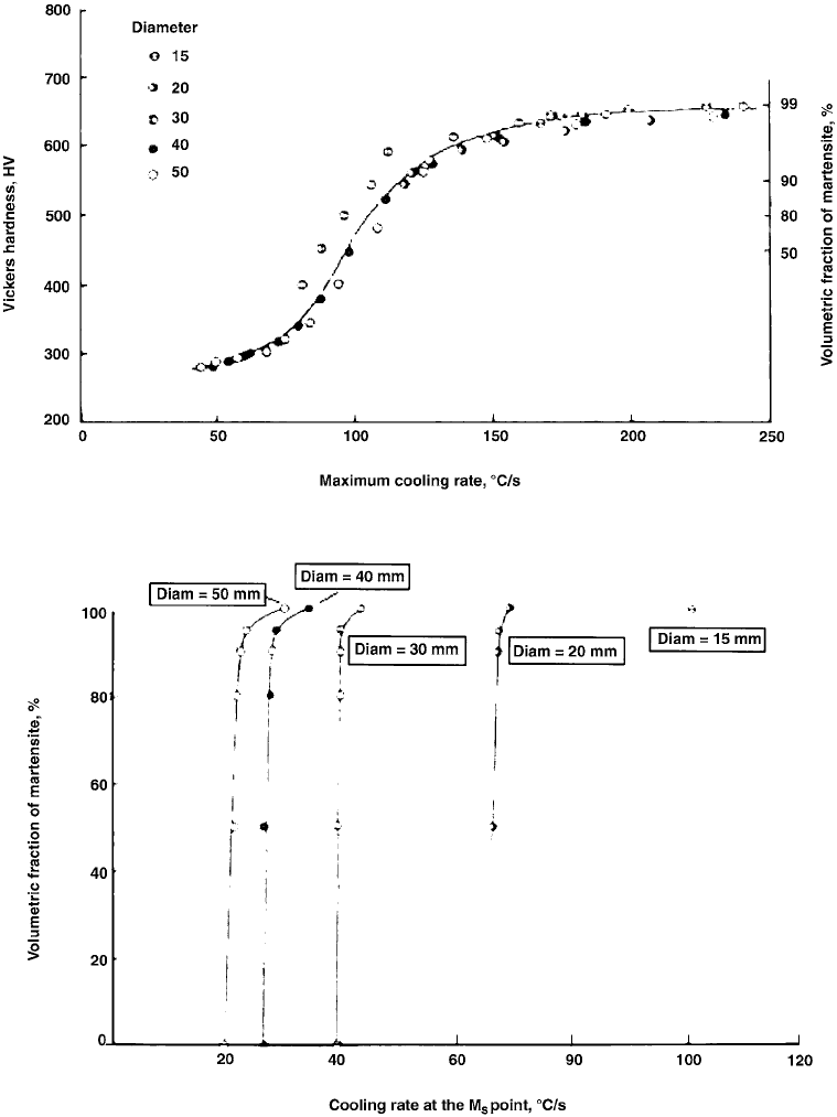
rate at the M
s
temperature for the steel (Fig. 11).
It is well known that retained austenite
can substantially affect distortion. Geller and
Brimene (Ref 11) published a nomogram that can
be used to predict dimensional changes caused
by the total carbon concentration in the marten-
sitic transformation product and the amount of
retained austenite. Steel chemical compositions
Fig. 10 Relationship between maximum cooling rate and volumetric fraction of martensite. Source: Ref 10
Fig. 11
Relationship between maximum cooling rate and the martensite start (M
s
) temperature and volumetric fraction of martensite.
Points in the same curve are related to different positions in the bar and therefore with the degree of martensitic transfor-
mation. Source: Ref 10
260 / Failure Analysis of Heat Treated Steel Components
Name ///sr-nova/Dclabs_wip/Failure_Analysis/5113_255-284.pdf/Chap_08/ 18/8/2008 3:28PM Plate # 0 pg 260

are found in Table 4. The following comments
will assist in interpreting the nomogram shown in
Fig. 12:
The shaded line represents zero distortion.
Steels with martensitic carbon contents and
retained austenite levels falling on the line
will exhibit essentially no distortion.
Martensitic steels with carbon contents and
retained austenite levels that fall bellow the
shaded line will exhibit shrinkage upon
quenching.
Martensitic steels with carbon contents and
retained austenite levels that fall above the
shaded line will exhibit expansion.
This nomogram was developed for various
construction and tool steels. Therefore, it should
be used with caution for other steel grades (e.g.,
high-speed tool steels).
Basic Distortion Mechanism. Shape and
volume changes occurring during heating and
cooling can be attributed to three fundamental
causes (Ref 12):
Residual stresses will cause shape change
when they exceed the yield strength of the
material.
Stresses caused by differential expansion
due to thermal gradients will increase with
the thermal gradient and cause plastic
deformation as the yield strength is ex-
ceeded.
Volume changes due to transformational
phase changes will be contained as residual-
stress systems until the yield strength is
exceeded.
When parts are heated during heat treatment,
a thermal gradient exists across the cross section
of the component. If a section is heated so that a
portion of the component becomes hotter than
the surrounding material, the hotter material
expands and occupies a greater volume than the
adjacent material and will thus be exposed to
applied stresses that will cause a shape change
when they exceed material strength. These
movements can be related to heating rate and
section thickness of the component.
Volume Changes During Phase Transfor-
mations. When a steel part is heated, it trans-
forms to austenite with an accompanying
reduction in volume. When it is quenched, the
structure transforms from austenite to marten-
site, and its volume increases. If these volume
changes cause stresses to be set up that are con-
strained within the strength of the material, a
residual-stress system is created. If the stresses
cannot be contained, material movement will
occur, which will cause cracking under extreme
conditions. The expansion is related to the com-
position of the steel. Figure 13 shows the relative
volume increase of two steels as a function of
austenitizing temperature and specimen dimen-
sions (Ref 13).
Table 4 Steel chemical compositions listed in Fig. 12
Russian
steel
desig-
nation(a)
Composition, wt%
C Si Mn Cr Ni Mo V Ti W Co Cu S P
U8 0.75–0.84 0.17–0.33 0.17–0.33 0.15 max ... ... ... ... ... ... ... 0.03
max
0.03
max
KhVG 0.90–1.05 0.10–0.40 0.8–1.10 0.90–1.20 ... ... ... ... 1.20–1.60 ... 0.30
max
0.03
max
0.03
max
ShKh15 0.95–1.05 0.17–0.37 0.20–0.40 1.30–1.65 0.30
max
... ... ... ... ... 0.25
max
0.02
max
0.03
max
7KhG2VM 0.68–0.76 0.20–0.40 1.80–2.30 1.50–1.80 ... 0.50–0.80 0.10–0.25 ... 0.5–0.9 ... 0.30
max
0.03
max
0.03
max
7KhG3V 0.68–0.76 0.20–0.40 3.0–3.5 1.50–1.80 ... ... 0.10–0.25 ... 0.5–0.9 ... ... ... ...
Kh12M 1.45–1.65 1.10–1.40 0.15–0.45 11.0–12.5 ... 0.40–0.60 0.15–0.30 ... ... ... ... 0.03
max
0.03
max
4Kh5V2FS 0.35–0.45 0.80–1.20 0.15–0.40 4.50–5.50 ... ... 0.60–0.90 ... 1.60–2.20 ... 0.30
max
0.03
max
0.03
max
3Kh2V8F 0.30–0.40 0.15–0.40 0.15–0.40 2.20–2.70 ... ... ... ... 7.50–8.50 ... 0.30
max
0.03
max
0.03
max
4Ch5W2FS 0.35–0.40 0.80–1.20 0.15–0.40 4.50–5.50 0.35
max
0.30 max 0.60–0.90 0.03
max
1.60–2.20 ... 0.30
max
0.03
max
0.03
max
3Ch2W8F 0.30–0.40 0.15–0.40 0.15–0.40 2.20–2.70 0.35
max
0.50 max 0.20–0.50 0.03
max
7.80–8.50 ... 0.03
max
0.03
max
0.03
max
R14M7K25 1.0 ... ... ... ... 7.0 ... ... 14.0 25.0 ... ... ...
N18K9M5 1.0 ... ... ... ... 5.0 ... ... ... 9.0 ... ... ...
(a) These compositional data were provided by Dr. Dmitry Wainstein, Surface Phenomena Research Group, Physical Metallurgy Institute, CNIICHERMET, Moscow,
Russia.
Steel Heat Treatment Failures due to Quenching / 261
Name ///sr-nova/Dclabs_wip/Failure_Analysis/5113_255-284.pdf/Chap_08/ 18/8/2008 3:29PM Plate # 0 pg 261
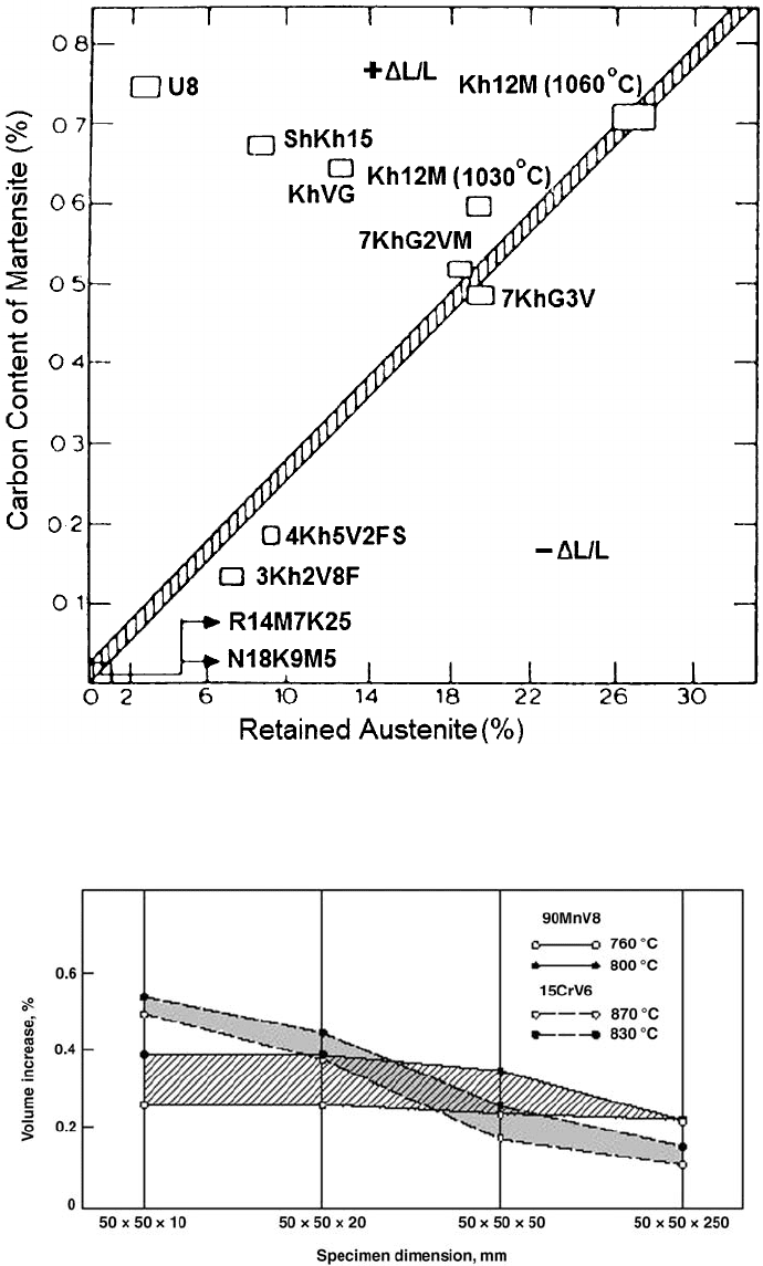
Fig. 12
Changes in linear dimensions during quenching relative to carbon concentrations in martensite and retained austenite.
Source: Ref 11
Fig. 13
Volume increase of 90MnV8 and 15CrV6 steels as a function of austenitizing temperature and specimen dimensions. Source:
Ref 13
262 / Failure Analysis of Heat Treated Steel Components
Name ///sr-nova/Dclabs_wip/Failure_Analysis/5113_255-284.pdf/Chap_08/ 18/8/2008 3:29PM Plate # 0 pg 262
While each of these phenomena is a well-
known physical change, the situation is made
more complex when all three events occur
simultaneously. In addition, other events, such as
heating rate, quenching, and inconsistent mate-
rial composition, further complicate the process.
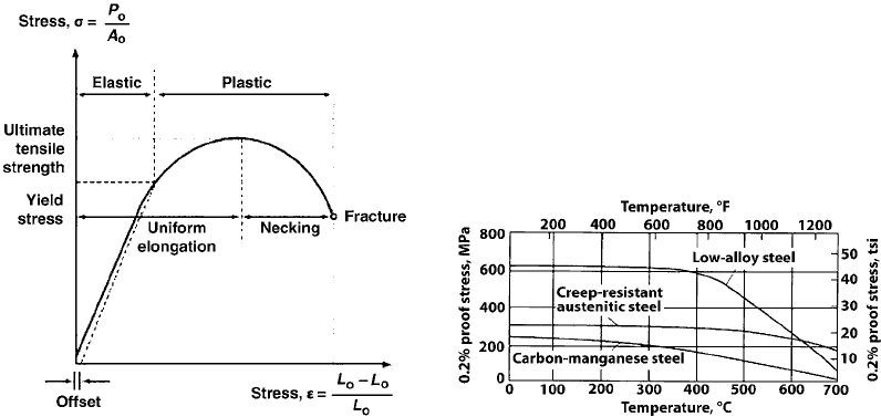
Relief of Residual Stresses. If a part has
locked-in residual stresses, these stresses can be
relieved by heating the part until the locked-
in stresses exceed the strength of the material.
A typical stress-strain curve obtained from a
tension test is shown in Fig. 14 (Ref 12). Initial
changes in shape are elastic, but under increased
stress, they occur in the plastic zone and are
permanent. Upon heating, the stresses are gra-
dually relieved by changes in the shape of the
part due to plastic flow. This is a continuous
process, and as the temperature of the part is
increased, the material yield stress decreases, as
shown in Fig. 15 (Ref 14). It is a function not
only of temperature but also of time, since the
material will creep under lower applied stresses.
It is apparent that the stresses can never be
reduced to zero, because the material will always
possess some level of yield strength below which
residual stresses cannot be reduced.
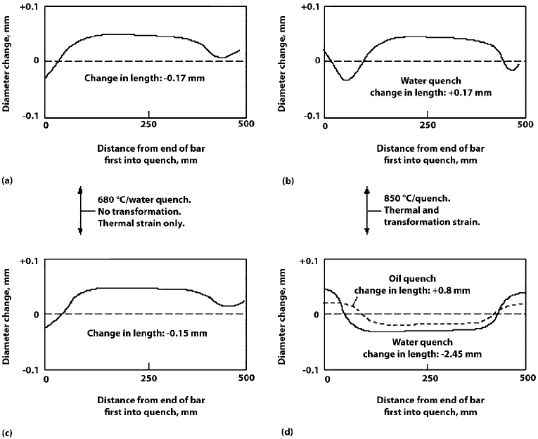
Effect of Materials and Quench Process
Design on Distortion
Quenchant selection and quenching condi-
tions are critically important parameters in
quench system design. For example, one study
compared the distortion obtained with quench-
ing of a 0.4% medium-carbon plain steel bar of
200 mm diameter by 500 mm long in water or
oil from 680
C (Ref 15, 16). The results, shown
in Fig. 16(a and c), show essentially equivalent
variation in diameter and length with both
cooling processes, which was due to thermal
strains within the steel. Interestingly, the well-
known diameter variations at the end of the bar,
known as the end effect, were observed, which
is attributable to heat extraction from both the
sides and ends of the bar (Ref 1).
If the same steel bars of the same dimensions
are heated to 850
C to austenitize the steel and
then are quenched in water or oil, the results
shown in Fig. 16(b and d), respectively, are
obtained (Ref 15, 16). Considerably greater
dimensional variation and lengthening of the bar
(for the oil quench) was obtained due to both
thermal and transformational strains within the
steel.
Thuvander and Melander modeled the
dimensional changes of a 70 mm steel (0.15%
C, 1% Mn, 0.75% Cr, 0.85% Ni) cube after
austenitizing and then quenching in water and
oil (Ref 15, 17). The results of this work are
shown in Fig. 17. They show that the edges and
faces shrink (becoming concave) and the effect
is greater when quenched in water than when
quenched in oil (Ref 1).
Various factors may affect distortion and
growth of steel during heat treating. These
include component design, steel grade and
condition, machining, component support
and loading, surface condition, heating and
atmosphere control, retained austenite, and the
quenching process (Ref 18).
Component Design
One of the overwhelming causes of steel
cracking and unacceptable distortion control is
Fig. 14
Various features of a typical stress-strain curve
obtained from a tension test. Source: Ref 12
Fig. 15
Variation of yield strength with temperature for three
generic classes of steel. Source: Ref 14
Steel Heat Treatment Failures due to Quenching / 263
Name ///sr-nova/Dclabs_wip/Failure_Analysis/5113_255-284.pdf/Chap_08/ 18/8/2008 3:29PM Plate # 0 pg 263
component design. Poor component design
promotes distortion and cracking by accentuat-
ing nonuniform and nonsymmetrical heat
transfer during quenching. Component design
characteristics that are common to distortion and
cracking problems include (Ref 19, 20):
Parts that are long (L) with thin (d) cross
sections. Long and thin parts are defined as
greater than L = 5d for water quenching,
L = 8d for oil quenching, and L = 10d for
austempering, where L is the length of the
parts, and d is the thickness or diameter.
Parts that possess large cross-sectional areas
(A) and are thin (t), which are defined as
A = 50t
Parts that exceed these dimensions must often
be straightened or press quenched to maintain
dimensional stability (Ref 20). If possible,
materials with sufficient hardenability should be
oil or salt quenched.
Design symmetry is also an important vari-
able to minimize distortion. For example, the
unsymmetrical gear design shown in Fig. 18(a)
may typically undergo distortion, as shown in
Fig. 18(b) (Ref 19). (The load on a gear tooth
increases by the 4.3 power of the taper, Ref 19).
The solution to the gear design problem shown
in Fig. 18 is to provide greater symmetry, as
shown in Fig. 19. If this is not possible, press
quenching or tooth-by-tooth induction hard-
ening may be the only solutions (Ref 19, 20).
Another common design problem is parts with
holes, deep keyways, and grooves. One illus-
tration of this problem is hardening of a shaft
with a lubrication cross hole, as illustrated in
Fig. 20 (Ref 19). Preferred alternative designs
are also shown in Fig. 20. If a radial cross hole is
Fig. 16
Dimensional variation of a medium-carbon (0.4%) steel bar (200 mm diam by 500 mm) after the indicated heat treatments.
These bars were quenched vertically with one end down (marked 0 in the figure). (a) and (c) show no transformation, only
thermal strain after water quenching from 680
C. (b) and (d) show thermal and transformation strains after quenching from 850
C.
Source: Ref 1
264 / Failure Analysis of Heat Treated Steel Components
Name ///sr-nova/Dclabs_wip/Failure_Analysis/5113_255-284.pdf/Chap_08/ 18/8/2008 3:29PM Plate # 0 pg 264