Canale L.C.F., Mesquita R.A., Totten G.E. Failure Analysis of Heat Treated Steel Components
Подождите немного. Документ загружается.

carbon-rich carburizing atmosphere. As the
temperature increases further to Ac
3
, additional
ferrite will transform to austenite by combining
with carbon from the furnace atmosphere, pre-
ferentially over carbon transfer from the spher-
oidal carbides already present until the austenitic
transformation is complete, at which point there
will be an equilibrium between the austenite and
carbides (Ref 112).
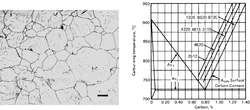
Those steels containing alloying elements
such as chromium and manganese that will
reduce the eutectoid carbon content and Ac
1
temperature are more likely to develop globular
carbides. These elements will increase the
solubility limit of carbon (A
cm
), thus shifting the
equilibrium diagram to the left, as shown in
Fig. 64 (Ref 112).
It should be noted that although the terms
spheroidal carbides and globular carbides are
often used interchangeably, these carbides may,
in fact, possess a round, angular, or even nee-
dlelike appearance. Also, although the structures
are typically designated as M
3
C, their actual
ratio of the element/carbon composing the car-
bide being observed is not only dependent on the
time and temperature of heat treatment but pri-
marily on the elemental availability in the steel
during formation.
There is a three-step process of high-density
carburizing that is conducted to increase case
hardness by aggressive precipitation of cemen-
tite (Fe
3
C) to improve surface fatigue strength
(Ref 113). Generally, grain-boundary carbide
precipitation will form network carbide struc-
tures that are susceptible to quench cracking and
result in reduced fatigue strength. Interestingly,
it is possible to obtain desirable surface fatigue
strength by vacuum or plasma carburizing a
chromium-containing steel such as SCr420H
or a chromium-molybdenum steel such as
SCM420H (Ref 114). This process involves the
formation of a M
23
C
6
-type globular carbide that
is approximately 1 mm in diameter. These
microstructures are reported to exhibit excellent
surface fatigue strength and rolling fatigue
strength under high bearing loads (43 GPa) at
relatively high temperature (100 to 300
C),
which are unachievable in the presence of larger
(i3 mm) M
3
C carbides.
Reheating a carburized steel to a temperature
below A
cm
causes spheroidized carbide particles
to form. (Both austenite and cementite are stable
at this temperature.) Since these carbides bind
some of the carbon in the case, there will be an
increase in the M
s
temperature. In addition,
grain-boundary migration is reduced (Ref 115).
Carbides are typically very hard. For exam-
ple, the microhardness of globular carbides in a
carburized case of a plain carbon steel has been
measured to be 41000 HV, and carbides in a 2%
Ni-Cr steel have been measured to be approxi-
mately 800 HV (Ref 112). Therefore, the pre-
sence of free globular carbides is often assumed
to improve component wear, abrasion, and
scuffing resistance. However, in a study reported
by Parrish on the effect of globular carbides on
contact fatigue with carburized 2% Cr-Mn steel,
it was shown that the presence of massive
Fig. 63
Bad globular carbide formation in the case of a car-
burized 9310 steel. Etchant: boil in alkaline sodium
picrate solution (45 s). Scale = 10 mm. Courtesy of G. Vander
Voort, Buehler Ltd., Lake Bluff, IL
Fig. 64
The saturation surface carbon content (A
cm
) of var-
ious carburizing steels as a function of carburizing
temperature as related to the iron-carbon equilibrium diagram
224 / Failure Analysis of Heat Treated Steel Components
Name ///sr-nova/Dclabs_wip/Failure_Analysis/5113_177-240.pdf/Chap_06/ 18/8/2008 3:21PM Plate # 0 pg 224
carbides was detrimental, while a beneficial
effect was obtained if the carbides were finer and
better distributed, as shown in Fig. 65 (Ref 112).
The presence of globular carbides may also
lead to grinding cracks, which are also related to
surface residual stresses.
Network Carbides. Globular carbides are
most typically formed when the carbon content
is less than the A
cm
. However, under some
conditions, it is possible for globular carbides to
still be formed when the carbon content is
greater than the solubility limit (in excess of the
eutectoid composition) and austenite is super-
saturated with respect to carbon. Most typically,
these are conditions where carbon will pre-
cipitate in the grain boundaries as cementite
(Fe
3
C) during slow cooling from the carburizing
temperature, leading to the formation of network
carbides. Figure 66 illustrates network carbide
structure observed in a broken carburized AISI
P5 steel tool.
The equilibrium diagram shown in Fig. 67
illustrates the conditions for the formation of
network carbides when excess carbon is pre-
cipitated from austenite as Fe
3
C (Ref 112).
When the carbon steel supersaturated with car-
bon content of C
1
is cooled from t
0
to t
1
,Fe
3
C
will begin to precipitate. As cooling continues
to t
2
, additional carbon will have precipitated
as Fe
3
C until the carbon content is C
2
. At the
eutectoid temperature t
3
, carbon precipitation as
Fe
3
C will have stopped, and the austenite carbon
content C
3
will transform to a pearlitic eutectoid
microstructure. The relative proportion of Fe
3
C
to austenite can be determined from Fig. 67
using the lever rule (C
x
C
1
/C
1
B).
Although austenite is supersaturated with
respect to carbon during the carburizing process,
and carbide precipitation at austenitic grain
boundaries will occur during cooling, if the steel
is quenched from the carburizing temperature,
the excess carbon can be retained by the result-
ing as-quenched martensitic/retained-austenite
microstructure. Typically, during carburizing,
the load is cooled in the furnace from the car-
burizing temperature to the temperature from
which the steel will be hardened. Since the Fe
3
C
migrates to the grain boundaries during slow
cooling, faster cooling by quenching will allow
retention of the carbon in the martensitic/auste-
nitic structure. Thus, cooling rate can be used to
control the amount of network carbide forma-
tion. Alternatively, carburized steel can be
cooled to ambient temperature and reheated to
820 to 860
C and quenched. However, it has
been shown that traces of the network carbides
remained in the microstructure even after heat-
ing to 900
C (Ref 112). Parrish also has
reported that if steel containing excess carbon is
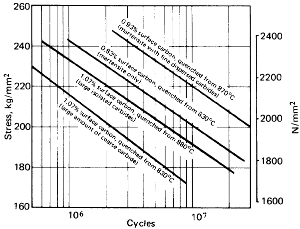
subcritically annealed prior to quenching, a fine
Fig. 65 Contact fatigue strength of carburized 25Kh2GHTA steel (tempered at 180 to 200
C)
Sources of Failures in Carburized and Carbonitrided Components / 225
Name ///sr-nova/Dclabs_wip/Failure_Analysis/5113_177-240.pdf/Chap_06/ 18/8/2008 3:21PM Plate # 0 pg 225
dispersion of relatively unharmful spheroidized
carbides will be obtained instead of network
carbides (Ref 112).
Karpov studied the effect of cooling from the
carburizing temperature on the nature of net-
work carbides formed when quenching gas-
carburized 11 by 11 by 56 mm 07Kh16N6 steel
test specimens. The test specimens were car-
burized, cooled, then reheated to austenitize to
1020
C, and then cooled to the quenching
temperature at 0.036
C/s, which is less than the
critical quenching rate that leads to network
carbide segregation. Quenching was conducted
in water at room temperature. From Table 11, it
is evident that network carbide formation begins
at 900 to 850
C for this alloy and is completed
at 600
C. From the phase diagram for this alloy,
the A
cm
temperature is 860
C (Ref 116). Dur-
ing the course of this work, Karpov found that a
nondestructive electromagnetic flaw detector
could be used to rank the network carbide size
(Ref 116).
Network carbides have been reported to
reduce surface fatigue (pitting) resistance of
carburized steel used for bearing applications
(Ref 114). Like globular carbides, complex
carburized networks in an overcarburized case
will reduce the potential for carbide redissolu-
tion during reheating, which will lead to in-
creased brittleness and grinding cracks (Ref 1).
The presence of network carbides in a Kaplan
turbine blade constructed from improperly car-
burized 17CrNiMo6 steel was reported to be a
major contributor to failure by an intergranular
microcracking mechanism (Ref 117). The
cracks seemed to follow the path of the network
carbide structure. Parrish has summarized var-
ious studies and concluded that continuous net-
work carbides do reduce fatigue properties,
leading to premature cracking failures by a
stiffening mechanism (Fig. 68) However, other
studies with partial nertwork carbides showed
no deleterious effects (Ref 112). The presence of
network carbides also is not expected to produce
an adverse effect with respect to wear under
heavily loaded conditions or scuffing (Ref 112).
The three most common failure modes of
carburized steels are ductile fracture, cleavage,
and intergranular fracture (Ref 23). Ductile
fracture is caused by nucleation growth and
coalescence of voids that are initiated at inclu-
sion sites and second-phase particles. Cleavage
fracture occurs by separation at crystallographic
planes by a transgranular pathway. Intergranular
fracture, such as that involving cementite
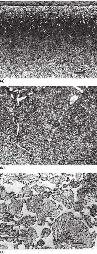
Fig. 66
Micrographs of a broken carburized P5 tool steel die.
Note the layer of cementite along the surface and the
heavy grain-boundary network in (a). The case was 59.5 HRC,
and the core was 22 GRC. (a) The case is shown at an original
magnification of 100· (100 mm bar). (b) The case at an original
magnification of 1000· (10 mm bar). (c) The core at an origi-
nal magnification of 400· (25 mm bar) in Nomarski differential
interference contrast (note the “old” and “new” ferrite, as in dual-
phase steel). The austenitizing temperature for the case is
approximately 1475
F, which is in the two-phase field for the
core. New ferrite formed due to limited hardenability in the
quench. Courtesy of G. Vander Voort, Buehler Ltd., Lake Bluff, IL
226 / Failure Analysis of Heat Treated Steel Components
Name ///sr-nova/Dclabs_wip/Failure_Analysis/5113_177-240.pdf/Chap_06/ 18/8/2008 3:21PM Plate # 0 pg 226
deposition at grain boundaries, involves crack-
ing on grain boundaries and is due to (Ref 23):
Precipitation of a brittle phase (such as net-
work carbides) on the grain boundary
Hydrogen embrittlement
Environmental-assisted cracking
Intergranular corrosion
Grain-boundary cavitation and high-
temperature cracking
Film or Flake Carbides. Surface-film or
flake carbides are composed of a continuous or
discontinuous carbide film with typically little or
no penetration into the case structure, which is
caused by cooling of the carburized steel in the
furnace with high carbon potential. Parrish
summarized various previously published re-
ports that stated such carbide films contain
approximately 19% Fe
3
C, 16% austenite, with
the balance being martensite. These films cover
a nonmartensitic layer of approximately 30 mm
thickness, with carbides penetrating into the
grain boundaries (Ref 112). Koistinen showed
that such films have high tensile surface
(0.025 mm depth) residual stress, as shown in
Fig. 69 (Ref 44). Until now, no further infor-
mation relating to the presence of these carbide
types on carburized steel properties has been
reported.
Fig. 67 The use of the iron-carbon equilibrium diagram to illustrate network carbide formation
Table 11 Effect of initial cool-down period on
network carbide formation of carburized
07Kh16N6 steel
Cool-down temperature(a), °C
Network carbide
severity rating(b)
1020 (initial temperature) 1
950 1
900 1–2
850 1–3
800 1–3
700 3–4
600 5–5
(a) The cooldown occurs from 1020 to the temperature shown at a rate of
0.036
C/s. (b) 1, very fine carbide network; 3–4, failure rating; 5, largest
Sources of Failures in Carburized and Carbonitrided Components / 227
Name ///sr-nova/Dclabs_wip/Failure_Analysis/5113_177-240.pdf/Chap_06/ 18/8/2008 3:21PM Plate # 0 pg 227
Noncarbide Inclusions
Two of the primary causes of fatigue failure
are inclusions and surface defects. Inclusions
may be metallic impurities or metallic oxides
(Ref 118). Metallic element inclusions (impu-
rities), although typically in trace quantities,
may be traced to the scrap used in the steel-
making process. These elements cause inter-
granular segregation, which may lead to crack
Fig. 68 Comparison of bending fatigue of carburized 12Khn3 gears showing adverse effect of network carbides
Fig. 69
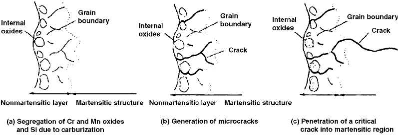
Residual-stress distribution of carburized SAE 1018 steel with a film-carbide layer formed due to a high carburizing potential.
The surface layer consisted of 16% Fe
3
C, 16% retained austenite, and the balance was as-quenched martensite.
228 / Failure Analysis of Heat Treated Steel Components
Name ///sr-nova/Dclabs_wip/Failure_Analysis/5113_177-240.pdf/Chap_06/ 18/8/2008 3:21PM Plate # 0 pg 228
formation, detrimental precipitate formation,
and are often observed as “slivers” in the final
product.
Metallic oxide inclusions vary in morphology
and composition. Some sources of these oxides
include:
Deoxidation products, such as alumina
inclusions, that are formed by the reaction of
dissolved oxygen and the added deoxidant,
such as aluminum. Alumina inclusions are
dendritic when formed in the presence of
high oxygen concentration.
Reoxidation products are generated when
the aluminum remaining in the liquid steel is
oxidized by FeO, MnO, or SiO
2
and other
oxides in the slag or refractory materials or
by exposure to the atmosphere.
Slag entrapment occurs in metallurgical
fluxes entrained in the steel. This occurs
during transfer between steelmaking vessels.
These inclusions are typically spherical.
Exogenous inclusions from other sources
include dirt, broken refractory brickwork,
and ceramic lining materials. They act as
sites for heterogeneous nucleation of alu-
mina and may include a central particle.
Chemical reactions may produce oxides
from inclusion modification when calcium
treatment is imperfectly performed. Inclu-
sions containing CaO may also originate
from entrained slag.
All steels contain various noncarbide in-
clusions. It is well known that inclusions, in
addition to surface defects and inhomogenities
such as retained austenite, nonmetallic inclu-
sions, and inhomogeneities, can reduce fatigue
strength and negatively influence ductility and
toughness (Ref 119). Although harder inclusions
such as metallic inclusions are more harmful
than softer inclusions, nonmetallic inclusions
are still generally harmful. In addition, the de-
leterious effects of inclusions increase with size.
In one study conducted by Bomas and
Schleicher on the effect of inclusions on the
fatigue strength of carburized 16MnCrS5 (SAE
5115) steel, it was found that subsurface fatigue
crack initiation was initiated by nonmetallic
inclusions up to depths of 1.4 mm (Ref 120).
Similar results were obtained for a study of
MnS-induced bending fatigue failure of car-
burized EN39B steel (Ref 121).
Even in clean steels, oxide and sulfide inclu-
sions exist. From a study of the effect of defects
such as inclusions on the fatigue bending
strength of carburized SCM20 steel, a model of
fatigue crack initiation during fatigue bending,
such as would occur in a gear tooth, was devel-
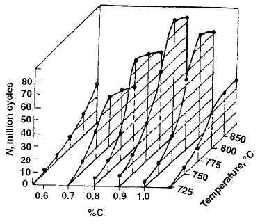
oped (Ref 122). This model is illustrated sche-
matically in Fig. 70. Figure 70(a) illustrates the
chromium and manganese oxides and grain-
boundary segregation of silicon oxides present
in a decarburized surface layer. When the sur-
face is loaded, the grain boundary or oxides act
as a stress raiser for microcrack formation, as
shown in Fig. 70(b). Although most of the cracks
remain in the decarburized layer, the most cri-
tical crack penetrates deeper into the steel, as
shown in Fig. 70(c). The crack that initiates fati-
gue failure was thought to be due to a combi-
nation of the microcracks shown in Fig. 70(b). In
this case, the decarburized layer in combination
with the presence of inclusions was projected to
be the source of fatigue failure (Ref 122).
Fig. 70
Model of fatigue crack initiation due to the presence of inclusions in a nonmartensitic (decarburized) steel layer. Source:
Ref 122
Sources of Failures in Carburized and Carbonitrided Components / 229
Name ///sr-nova/Dclabs_wip/Failure_Analysis/5113_177-240.pdf/Chap_06/ 18/8/2008 3:21PM Plate # 0 pg 229

Micropitting
Micropitting fatigue usually occurs on heav-
ily-loaded surface-hardened components and
is characterized by a frosted or gray-stained
appearance under thin-film lubrication condi-
tions (Ref 87, 123). Numerous small cracks in
the surface may exceed the depth of the micro-
pits (Ref 124). Under magnification, small pits
approximately 10 mm deep will be observed.
The surface will appear etched with a pattern
that sometimes follows the slightly higher ridges
left by cutter marks or other surface irregula-
rities on the finished component. Micropitting is
influenced by high surface loads, frictional heat
generation due to poor lubrication caused by
insufficient film thicknesses in the partial elas-
tohydrodynamic lubrication regime, excessive
retained austenite, tangential speed, and lubri-
cant additives and oxidation (Ref 123).
Micropitting is strongly influenced by the
relative lubricating oil film thickness and can
be quantitatively related to both the surface
condition (roughness) and the thickness of
the lubricating film by the lambda (L) value
(Ref 124, 125):
L=h=s=
h
ffiffiffiffiffiffiffiffiffiffiffiffiffiffiffiffiffiffi
(s
2
1
+s
2
2
)
q
where s
1
and s
2
are the root mean square surface
roughness of the two opposing wear surfaces,
and h is the lubricating oil film thickness. When
Li3, there is full film lubrication with no
asperity contact. When 0.85L53, there is
partial elastohydrodynamic lubrication. When
L50.8, there is a boundary lubrication condi-
tion. When L51, micropitting will occur, and
once micropitting occurs, pitting fatigue (mac-
ropitting) will be accelerated (Ref 124). How-
ever, if macropitting does occur, it is often
characterized by an arrowhead or fan shape (Ref
123). There have been reports of substantial
improvements in fatigue lives, such as with
carburized 9310 steel, with corresponding reduc-
tions in surface roughness (Ref 125).
For gears, there is a critical temperature where
pitting fatigue and scuffing are likely to occur.
This is called the critical scuffing temperature
(T
c
), which is calculated from:
T
c
=T
b
+T
f
where T
b
is the equilibrium temperature of
the gears before meshing, and T
f
is the flash
temperature, which is the instantaneous tem-
perature rise due to localized friction heat at the
point where the gear teeth mesh. The value of T
b
is controlled by gear geometry design, and the
value of T
f
is controlled by the lubricant visc-
osity and surface roughness.
To minimize micropitting:
Use higher operational speeds and smooth
material surfaces.
Use the recommended amount of clean, dry
lubricant with the highest viscosity permis-
sible.
Reduce the lubricating oil temperature and
surface loading.
Use the optimal amount of case carbon
content in carburized gear materials.
Contact Fatigue Pitting (Macropitting)
Pitting failures occur when fatigue cracks are
initiated on the tooth surface or just below the
surface. Usually, fatigue pits are the result of
surface cracks caused by metal-to-metal contact
of asperities or defects due to insufficient lubri-
cant film thickness. They are dependent on the
Hertzian contact surface stress and the number
of stress cycles (Ref 124). Surface asperities of
the harder material of a wear contact will lead to
damage of the softer surface, sometimes by a
work-hardening mechanism, leading to the
creation of microcracks that then become fatigue
pits as the wear process continues (Ref 124).
Pitting damage is commonly encountered with
rolling element bearings, gears, and machine
components subject to cyclic rolling-sliding
motion under a load. Initially, fatigue pits may
occur in localized areas and may range in size
from 0.38 to 0.76 mm (0.015 to 0.030 in.) in
diameter (Ref 85).
Vinokur et al. examined the effect of case
carbon content of carburized 18KhGNMFL steel
(1.3% Mn, 1.3% Cr, 0.8% Ni, 0.25% Mo, 0.1%
V) on the contact endurance of fatigue tests
conducted with a wear test with an applied stress
of 3500 MPa using a lubricating oil. Contact
fatigue was the average of 10 tests to determine
the number of cycles until pitting was observed.
The case depth was approximately 1.8 mm. The
carburized steel was hardened from the inter-
critical range and tempered at 170
C. The
results of this study are summarized in Fig. 71
(Ref 126). The contact endurance increases with
carbon content up to approximately 0.9% C and
230 / Failure Analysis of Heat Treated Steel Components
Name ///sr-nova/Dclabs_wip/Failure_Analysis/5113_177-240.pdf/Chap_06/ 18/8/2008 3:22PM Plate # 0 pg 230
then decreases. The optimal hardening tem-
perature was at approximately 850
C, which is
in the intercritical temperature range, just below
the upper critical temperature for the steel.
Although fatigue pits are usually initiated at
the surface, subsurface initiation is relatively
common in case-hardened rolling element
bearings with serious inclusion problems. In
these situations, failures usually do not follow
the case-core interface (Ref 125, 127). The
potential for micropitting, pitting, and spalling
phenomena may be assessed from the lambda
(L) value (see the section “Micropitting” in this
chapter); however, even relatively smooth sur-
faces and lubricating film thickness, such as
those used for high-speed gears, may exhibit
pitting failures due to the presence of subsurface
cracks. The subsurface cracks may be caused by
the presence of inclusions that act as stress
concentrators, causing the crack to propagate
parallel to the surface and subsequently break
through the surface.
Spalling failure occurs when the wear process
causes several pits to join together. These larger
craters are usually caused by more severe over-
loading conditions. As the number of stress
cycles increases, the pitting process will con-
tinue in an effort to relieve stresses. The rule is
that spalling cracks initiate where the ratio of
shear stress to Vicker’s hardness is maximum
(Ref 124). However, this relationship is not
correct when there are excessive amounts of
retained austenite. Generally, it is assumed that
spalling will occur when L41.
To prevent pitting fatigue, either the surface
loading must be decreased to a level below the
endurance limit of the material or the hardness
must be increased to increase the endurance
limit (Ref 28). Pitting may also be reduced by
instituting a break-in period at reduced loads and
speeds to improve gear tooth contact (Ref 85,
124].
Other potential causes of fatigue pitting
include hydrogen embrittlement due to water
contamination of the lubricant and particle
contamination of the lubricant, which act as
surface stress-concentration points that lead to
pitting failure.
Case Crushing
If the case depth is too deep, case-core
separation may occur due to the tips of the gear
teeth becoming too brittle and possibly break-
ing, if the case depth is too thin, the strength
of the gear teeth will be reduced, causing pre-
mature pitting, or it may lead to a condition
called case crushing (Ref 131). Case crushing
occurs in heavily loaded case-hardened com-
ponents such as gears. Case crushing occurs by a
subsurface fatigue process where the high-cycle
contact stress exceeds the endurance limit. This
will occur when subsurface stresses exceed the
strength of the core. Case crushing failures may
have a similar appearance to pitting, although it
often occurs as longitudinal cracks on the sur-
face of only one or two gear teeth, where sec-
tions of the tooth surface may subsequently
break away. However, the case material may
appear to have chipped away from the core in
large flakes (Ref 85). The observed cracks will
move toward the case-to-core boundary and then
to the gear surface (Ref 129).
Adequate case support is provided by proper
core structure to not only prevent case crushing
but also to transmit torque, support bending
loads, and provide adequate toughness to prevent
brittle fracture. The presence of any ferrite will
contribute to reducing the toughness of the core.
Case crushing may be prevented by increasing
the case depth and possibly the core hardness.
For general applications where core hardnesses
of 30 to 45 HRC are specified, the required case
depth can be estimated from (Ref 128):
Case depth to 50 HRC=½1:2 · 10
7
(W)=F
where W is the force in pounds pressing the
surfaces together, and F is the length of the line
Fig. 71
Effect of case carbon content and hardening tem-
perature on the contact endurance limit of carbur-
ized 18KhGNMFL steel (1.3% Mn, 1.3% Cr, 0.8% Ni, 0.25% Mo,
0.1% V). Source: Ref 126
Sources of Failures in Carburized and Carbonitrided Components / 231
Name ///sr-nova/Dclabs_wip/Failure_Analysis/5113_177-240.pdf/Chap_06/ 18/8/2008 3:22PM Plate # 0 pg 231
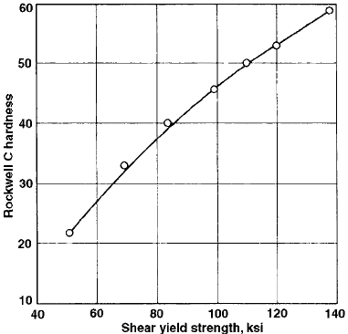
contact in inches. The strength of the core can be
determined from hardness. Since case crushing is
promoted by shear, the shear strength of the core
must be determined and can be estimated from
Fig. 72 (Ref 128). Generally, the subsurface
stress/strength ratio should not be greater than
0.55.
Eryu et al. have studied case-crushing fracture
mechanisms of carburized 20CrMnTi by
scanning electron microscopy (Ref 130). They
showed that the surface features of the primary
cracks exhibited scaly features and that there
were two features of the fracture surfaces of the
branching cracks. The fatigue steps and dimples
were analogous to materials of higher strength,
and the fragmentation pattern was analogous to
brittle material. In addition, spherical particles
were observed that were composed of a-iron,
which were proposed to be caused by the
movement of the faces of the primary crack due
to shearing and compressive stresses.
Pitting Corrosion
Pitting corrosion is a localized penetrating
corrosion attack of typically corrosion-resistant
steel resulting in a mass loss of the steel (Ref
131). Pitting corrosion is related to localized
discontinuities of a passive layer caused by
mechanical imperfections, inclusions, surface-
localized chemical attack of the passive layer by
salts such as chlorides, or by overaggressive
lubricant additives. After the corrosion pit is
created, the localized chemical surrounding is
much more aggressive than the surrounding area
of the uncorroded material.
Initiation of the pitting process is dependent on
temperature and on the steel surface, including
the presence of sediment. In some applications
where pitting corrosion is more prevalent, such
as steel in concrete structures, the pitting corro-
sion process is characterized by the temperature
or narrow range of temperatures above which
pitting will nucleate. The creation of corrosion
sediments will lead to a temperature decrease.
Pitting corrosion will only occur above this cri-
tical temperature. Therefore, to increase the
lifetime of steel used in reinforced concrete by
reducing the rate of pitting corrosion, frequent
sediment removal (cleaning) is recommended.
Most often, pitting corrosion is initiated by the
presence of chloride salts, and the rate of cor-
rosive attack is steel alloy dependent. The cri-
tical concentration of chlorides for different
steel alloys cannot be defined, because corro-
sivity is dependent on other chemicals that may
be present, which will affect the rate of corrosion
attack. However, since pitting corrosion is
typically relatively fast, it should be prevented.
Resistance of steel to pitting corrosion is
dependent on the alloy composition (chromium,
molybdenum, tungsten, nitrogen). Relative cor-
rosion resistance of steel alloys may be empiri-
cally quantified by:
Relative corrosion resistance=%Cr
+3:3 ½%Mo+0:5 (%W)+16 (%N)
Chromium and molybdenum are also useful
alloy additions to minimize the potential for
stress-corrosion cracking.
Corrosion pitting may also be caused by
chemical attack of the steel surface by lubricant
additives such as extreme-pressure additives,
particularly in the presence of acid, water, or
contaminants. Also, during use, the oil itself will
oxidatively degrade, producing acidic by-pro-
ducts that may lead to corrosion pitting. In
addition to pitting, corrosive attack may occur at
the grain boundaries of the carburized case. It is
particularly important that components exposed
to saltwater, liquid chemicals, or other foreign
materials during use should be sealed from their
operating environment (Ref 85).
Pitting corrosion may also occur during heat
treatment, particularly those processes involving
salt baths (Ref 132). Heating of steel with scale
on a surface not only accelerates decarburizing,
Fig. 72
Shear strength of carburizing steels as a function of
hardness
232 / Failure Analysis of Heat Treated Steel Components
Name ///sr-nova/Dclabs_wip/Failure_Analysis/5113_177-240.pdf/Chap_06/ 18/8/2008 3:22PM Plate # 0 pg 232
but pitting corrosion is also accelerated. The
corrosive attack is increased with temperature
and holding time. If the scale is not uniform, then
pitting corrosion is localized to those areas
where scale is present. If residual salt from the
bath crystallizes on the surface of the steel,
violent boiling may occur during subsequent
quenching in oil, which may result in blister
formation on the surface. After cleaning, loca-
lized pitting corrosion will then occur. To avoid
pitting corrosion during furnace heating, parts
should be thoroughly cleaned.
In some cases, stainless steel machine parts
are carburized to reduce wear. However, car-
burizing a stainless steel (1Kh16N2AM) reduces
corrosion resistance where machine parts are
used in humid environments (Ref 133). The
potential for pitting corrosion increases as the
amount of d-ferrite increases. Corrosion resis-
tance is reduced as the quenching temperature
prior to carburizing is increased. Although
increasing the quenching temperature after car-
burizing to 950 to 1100
C does not affect cor-
rosion resistance, decreasing the quenching
temperature to 800 to 850
C reduces corrosion
resistance. Increasing the tempering tempera-
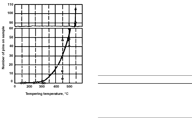
ture decreases corrosion resistance, as shown in
Fig. 73 (Ref 133). The corrosion resistance of
carburized steel is greatest after stress relieving
at 250
C.
Partial Melting
Partial melting occurs when there is nonuni-
form heating of the surface of the steel, such that
some areas are heated to the liquation tempera-
ture (the partial melting temperature of an alloy)
(Ref 77, 131). Corners and edges are particularly
susceptible to partial melting. Microscopically,
the presence of partial melting is typically
observed as black spots containing retained
austenite in a large cluster of carbides. Macro-
scopically, partial melting is accompanied by
the formation of tiny surface cracks.
Partial melting occurs when the carburized
steel is heated to an excessively high tempera-
ture, resulting in incomplete or selective car-
burizing of the surface. For example, partial
melting may occur during stray current flow into
the load from electrodes used to heat salt pot
furnaces or if a load is placed too close to the
furnace hearth, so that some areas of the load are
heated to an abnormally high temperature. To
avoid this defect, heating in salt baths with
appropriate composition and at appropriate aus-
tenitizing temperature should be conducted by
keeping the load at a recommended distance
from the heating electrodes. Similarly, when
heating in a conventional furnace, the load
should be properly placed to facilitate uniform
heating.
It is also important to be aware of the liquation
temperature (beginning of melting) of the alloy
being heated. Some typical examples of the
approximate liquation temperatures for different
steels are provided in Table 12, where the
soaking temperature is 2 to 3 min. Precise defi-
nition of the partial melting temperature range is
typically a difficult task, because of the rela-
tively large data scatter due to potential com-
positional variation within the alloy, variation of
carbon content, and, in some cases, relatively
large carbide segregation. These structural var-
iations favor the potential for partial melting to
Fig. 73
Effect of tempering temperature on corrosion resis-
tance of carburized stainless steel 1Kh16N2AM. The
corrosion test was conducted in a humidity cabinet. Source:
Ref 133
Table 12 Approximate liquation temperature
for various steel alloys
Steel alloy
Approximate liquation
temperature, °C
SW14 1320
SW18 1330
SW7Mo 1280
SK5 1350
SKC 1280
SK5V 1270
SW12C 1260
SK10V 1250
Sources of Failures in Carburized and Carbonitrided Components / 233
Name ///sr-nova/Dclabs_wip/Failure_Analysis/5113_177-240.pdf/Chap_06/ 18/8/2008 3:22PM Plate # 0 pg 233