Canale L.C.F., Mesquita R.A., Totten G.E. Failure Analysis of Heat Treated Steel Components
Подождите немного. Документ загружается.

the core consisted of pearlite and ferrite. Upon
rapid cooling, the carburized case had a small
amount of martensite with a correspondingly
lower amount of pearlite, and in the core, a lower
amount of ferrite with the remainder being pear-
lite was obtained. However, for the 12KhN3A
alloy, air cooling produced predominantly mar-
tensite and retained austenite in the case and
correspondingly less pearlite. The core con-
tained bainite (Ref 76).
In practice, it was shown that gears manu-
factured from 20KhGB steel exhibited an aver-
age reduction in diameter (0.7 to 1.4 mm) from
463+0.3 after carburizing. This was attributed
to reduced stability of austenite in the pearlite
region. Conversely, for the 12KhN3A steel, the
gears increased in size (0.2 to 0.5 mm) after
carburizing because austenite was more stable in
the pearlite region. These data suggest that dis-
tortion can be controlled by alloy and cooling
rate selection, or improper selection of cooling
rate or alloy can result in unacceptable compo-
nent distortion (Ref 76).
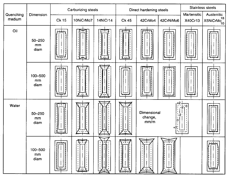
The effect of phase transformation behavior
in the case and the core due to thermal gradients
such as those occurring during heating and
cooling will affect shape and size distortion of
small parts, as illustrated by Fig. 32 (Ref 19). If
the thermal and transformational stresses exceed
the yield strength of the steel, corresponding
distortion will occur.
Quenching and Grinding Cracks (Ref 77)
Quenching cracks occur when tensile
stresses of the first kind are greater than the
material strength. Quenching cracks typically
occur during, or in some cases after, quenching at
temperatures less than the M
s
temperature. Sus-
ceptibility to cracking increases with the carbon
content of the steel, increasing austenitizing
temperature, and cooling rate, especially in the
M
s
M
f
transformation temperature range.
The probability of cracking during quenching
increases with the presence of stress raisers
Fig. 32 Resulting distortion after heat treatment of different steels after quenching in oil and water
204 / Failure Analysis of Heat Treated Steel Components
Name ///sr-nova/Dclabs_wip/Failure_Analysis/5113_177-240.pdf/Chap_06/ 18/8/2008 3:19PM Plate # 0 pg 204
such as notches, abrupt changes in section size,
keyways, and holes. Quenching cracks are irre-
versible but can be minimized by appropriate
design modifications, reduction in hardening
temperature, and use of lower quench severity.
The reasons for the occurrence of quenching
defects include:
Poor surface cleanliness, such as residual
forging and metalworking lubricants, and so
on, which leads to nonuniform quenching,
increased thermal gradients, and soft spots
Incorrect loading and arrangement of parts
in the furnace, which leads to nonuniform
heating and related distortion
Excessive heating rates, which may lead to
warping and cracking
Lack of a protective atmosphere to eliminate
oxidation and decarburization of the steel
surface, which will lead to reduction in
mechanical properties after hardening and
a decrease of hardness of the superficial
layer
Excessive cooling rates and incorrect im-
mersion into the quenching bath, causing
cracking, warping, and twisting
Insufficient cooling rates or undersized
quench tanks, which will inhibit the desired
martensitic transformation
Quenching cracks, which are characterized by
relatively large depth and short length, rarely
occur in the case of carburized or carbonitrided
components. This can be explained by more
beneficial compressive surface stresses than
those typically formed in higher-carbon-
containing through-hardened parts. However,
internal cracks may form in the core below the
carburized surface or in the transition zone, that
is, in the places with the largest tensile stresses in
carburized parts. Cracks may also form on the
surfaces and corners of carburized parts, which
is related to triaxial tensile stresses in these
locations. Therefore, to prevent cracking, the
case must be sufficiently deep so that stresses
developed at any point below the surface are less
than the fatigue limit of the material at that point
(Ref 1).
When steel contains greater than 0.5% C in a
martensite matrix, such as in the carburized case,
intergranular fracture along prior-austenite grain
boundaries may occur. In this situation, the
intergranular fracture is due to the presence of
both phosphorus and cementite formation on the
austenite grain boundaries during austenitizing
or cooling from austenitizing temperatures.
Krauss has referred to this fracture mechanism
as quench embrittlement and has suggested
that the mechanism for this to occur is analogous
to quench cracking in through-hardened steels,
which is due to the formation of tensile sur-
face stresses during quenching, as described
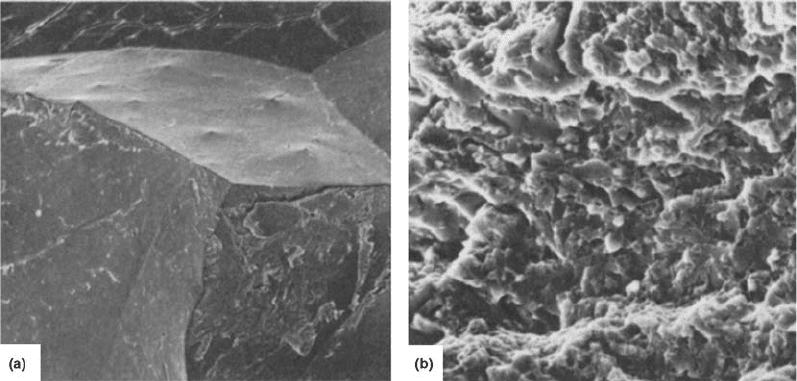
previously (Fig. 33) (Ref 78). However, since
relatively high surface compressive stresses are
present in properly carburized steels, quench
cracking should not exist if conditions for po-
tential intergranular cracking are present.
Fig. 33
Scanning electron micrographs of overload case fracture surfaces in carburized SAE 8620 steel. (a) Quenched directly after
carburizing at 927
C (1700
F). (b) Reheated to 788
C (1450
F). Both specimens were tempered at 145
C (300
F).
Sources of Failures in Carburized and Carbonitrided Components / 205
Name ///sr-nova/Dclabs_wip/Failure_Analysis/5113_177-240.pdf/Chap_06/ 18/8/2008 3:19PM Plate # 0 pg 205
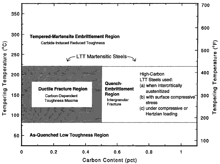
Krauss has reported that carburized steels will
fail by intergranular cracking if sufficent bend-
ing or tensile stresses are applied to offset the
compressive stresses in carburized cases. The
fracture map shown in Fig. 34 illustrates three
conditions where susceptibility to intergranular
cracking can be minimized: carburizing, inter-
critical austenitizing, and applications where
loading is Hertzian or compressive (Ref 79).
In some cases, microcracking can occur with
higher-carbon lath martensite matrices, which
are present in the hardened carburized case.
Microcracking is due to contact of martensitic
plates with each other or with the austenitic grain
boundaries. The potential for microcracking
increases with the austenization temperature.
Prior-austenite grain size also affects micro-
crack density, which decreases with decreasing
prior-austenite grain size. However, microcrack
density is not affected by quench severity
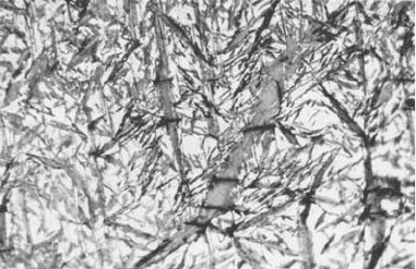
(Ref 78, 80). Figure 35 illustrates examples of
microcrack formation in the carburized case of
SAE 8620 steel (Ref 78).
The presence of microcracks can further lead
to a surface defect called flaking, which refers to
flakelike fracture and subsequent peeloff. (Note:
Flaking is initiated at microcracks that may also
be caused by surface damage due to lubricant
contamination by chips, shavings, burrs, or
abrasive powder ingression into the lubricating
system.)
Krauss reported that fatigue resistance
decreased with increasing microcrack forma-
tion. Crack initiation occurred at the site of the
microcrack that acts as a stress concentrator (Ref
78). Although microcracks can be removed by
surface grinding and polishing, fatigue failure
may still be initiated at prior-austenite grain
boundaries, intergranular surface oxides, or
surface defects such as scratches, machining
marks, and surface asperities due to roughness.
Aksenova et al. showed that contributing
factors to cracking of case-hardened gear wheels
included residual tensile stresses in the case-core
interface, grain growth and overheating, super-
saturation of the case with carbon, excessively
high cooling rates during quenching, too low
a quenching temperature, and insufficient resi-
dence time in the quench tank after immersion
(Ref 81).
Fig. 34
Krauss fracture map illustrating conditions where susceptibility to intergranular cracking can be minimized: carburizing,
intercritical austenitizing, and Hertzian or compressive contact loading
206 / Failure Analysis of Heat Treated Steel Components
Name ///sr-nova/Dclabs_wip/Failure_Analysis/5113_177-240.pdf/Chap_06/ 18/8/2008 3:19PM Plate # 0 pg 206
McEvily et al., reported the use of fracto-
graphic analysis to explain cracking of a
carburized AISI 9310 gear at the case-core
transition zone. One of the factors was the dif-
ferential in the Poisson ratio (n) between the case
and the core that develops during a monotonic
bending test when the core deforms plastically
while the case deforms elastically. McEvily
used as an example to illustrate this point a
9 mm diameter round bar with a 1 mm case.
When the bar is first loaded initially and the
deformation is elastic, the Poisson ratio for the
case and the core is equal. Upon further bending,
the core will deform plastically while the case is
deforming elastically. However, because of the
difference in the Poisson ratio between the case
(n = 0.3) and the core (n = 0.5) at this point,
radial tensile stresses will develop. For a tensile
strain of 1%, the radial strain in the case (relative
to the centerline) would be 0.003, and the radial
strain in the core would be 0.005. To remain
compatible, the difference in the strain and
corresponding displacements must be accom-
modated by the formation of a tensile stress.
However, this radial stress will result in a state of
triaxial stress that will promote brittle behavior
by inhibiting plastic deformation. The total
tensile stress may then be developed sufficient
to result in rupture at the case-core interface
(Ref 82).
Grinding Cracks. Grinding may be used for
postprocessing of components to remove growth
and distortion that may have resulted from car-
burizing and carbonitriding. Grinding is also
performed to remove such metallurgical features
as carbide films, internal oxidation, and high-
temperature transformation products that may
impart deleterious performance properties. In
addition, grinding processes are commonly used
to create the desired surface finish to improve
bending and contact fatigue and lubrication
properties.
Surface cracks in the carburized case may
occur during the grinding process, which can be
attributed to microstructural transformations
and thermal stresses producing tensile forces. If
the tensile forces in the case exceed the material
strength, then surface cracks will result. This is
due to the difference in the specific volume of
the transformational phases present in the case
structure, primarily martensite and austenite.
Structural defects, such as those caused by
inclusions, will also influence the susceptibility
of the steel to cracking.
Generally, crack creation during grinding is
influenced by thermoelastic tensile stresses that
are created in the surface cooling zone during
grinding. They are dependent on thermal and
mechanical properties of the material, maximum
contact temperature, grinding feed depth, and
cooling rate.
One study conducted on the generation of
grinding cracks showed that microstructural
heterogeneity, such as the presence of carbide
inclusions (particularly those with a mean dia-
meter of 6 to 10 mm), which were shown to be
associated with large internal residual stresses,
were a predominant cause of grinding cracks
(Ref 83).
Grinding burns arise when excessive heat is
generated during the grinding process, and this is
characterized by surface discoloration. The term
grinding burn refers to localized surface tem-
perature increases at least sufficient to cause
tempering of the martensitic surface, resulting in
localized soft spots. Furthermore, since carbide
precipitation volume contraction accompanies
tempering, the burnt areas are in tension and, if
the resulting tensile stresses are sufficient, sub-
ject to tranverse cracking. However, in other
cases, the increase may be in excess of the Ac
3
temperature, producing an austenitic surface
that, upon rapid cooling, may produce a hard,
light-etching, martensitic thin layer at the sur-
face. This induced defect is known as a rehar-
dening burn, which is characteristically
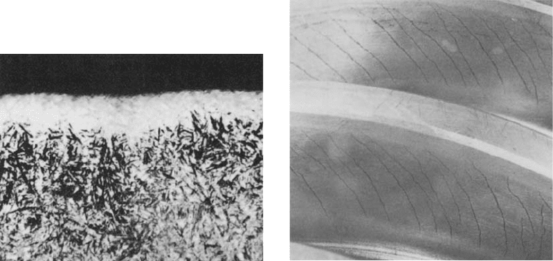
surrounded by a layer of tempered steel (Fig. 36)
(Ref 84). In this case, the rehardened zone is in
compression due to the martensitic volume
expansion, and the surrounding areas of tem-
pered martensite are in relative tension. Crack-
ing may occur in the area surrounding the
rehardened material or in the interface between
the two (Ref 84).
Fig. 35
Microcracks in the martensitic case of a coarse-
grained SAE 8620 steel
Sources of Failures in Carburized and Carbonitrided Components / 207
Name ///sr-nova/Dclabs_wip/Failure_Analysis/5113_177-240.pdf/Chap_06/ 18/8/2008 3:19PM Plate # 0 pg 207
There are two possibilities to prevent the
occurrence of thermal defects in the surface
resulting from the grinding process:
Reduction of heating due to the rotation of a
grinding wheel by reducing the speed of the
grinding wheel will reduce heating and
friction. Conversely, increasing the speed of
the grinding wheel will increase heat pro-
duction and the potential for the formation of
grinding burns due to overheating.
Increasing heat abstraction due to the
grinding process and reducing the contact
time between the grinding wheel and part
will reduce the tendency for grinding burns.
Grinding cracks may exhibit characteristic
short, parallel cracks (Fig. 37), or they may
exhibit a “chicken-wire” pattern and are typi-
cally between 0.076 and 0.13 mm (0.003 and
0.005 in.) deep. The parallel cracks are typically
deeper than the chicken-wire pattern. Grinding
cracks form perpendicular to the grinding
direction. As indicated previously, the potential
for grinding cracks is affected by improper heat
treatment or a metallurgical structure that is
prone to cracking. For example, if the surface
temperature exceeds the Ac
3
temperature, the
steel in this region may transform to austenite,
then upon rapid cooling, a hard martensite layer
may form. This effect is called a rehardening
burn. Grinding cracks may be detected by a
magnetic particle test.
Some carburizing steels such as chromium
and chromium-manganese steels, which include
SAE 5120 and 20MnCr5, may undergo over-
carburizing with subsequent cracking of the case
upon cooling, which then renders the part more
susceptible to the formation of grinding cracks
(Ref 1). Overcarburizing leads to the formation
of a complex carbide network that is excessively
brittle, which causes greater susceptibility to
grinding cracks.
Severe grinding may lead to the development
of residual tensile stress, which can be the
initiation point for crack formation. Since cracks
will not propagate into layers of compressed
stress, it therefore may be advantageous to shot
peen the part prior to grinding to prevent the
formation of grinding cracks (Ref 86).
Parrish reported that the potential for forma-
tion of grinding cracks may be minimized by
(Ref 84):
The thermal conductivity of the steel is an
important design variable, and free carbides
and retained austenite have an adverse effect
on thermal conductivity.
The surface carbon concentration should be
between 0.7 and 0.9%.
Parts should be tempered immediately after
quenching.
The tempering temperature should be as
high as possible while still achieving the
necessary surface hardness.
Improper Case Depth (Ref 77). In a recent
study conducted by Bahnsen et al. on carburized
SAE 5120 test specimens to rate the relative
influence of surface carbon content, case depth,
and carburizing temperature on distortion, it was
Fig. 37
Example of grinding cracks on the flank of a worm
gear. Source: Ref 85
Fig. 36
Microstructure of a section through a rehardening
burn. Original magnification: 500·
208 / Failure Analysis of Heat Treated Steel Components
Name ///sr-nova/Dclabs_wip/Failure_Analysis/5113_177-240.pdf/Chap_06/ 18/8/2008 3:19PM Plate # 0 pg 208
reported that of these variables, the most domi-
nant effect was observed for case depth (Ref 87).
Case depth of carburized steel is determined by
the carburizing time and the available carbon
potential at the surface. One of the most com-
mon defects of carburized and carbonitrided
materials is an insufficient or excessive case
depth. For example, when prolonged carburiz-
ing times are used to produce a deep case depth,
a high carbon potential will produce a high
carbon content on the surface and the possible
corresponding formation of excessive retained
austenite or free carbides, which may lead to an
improper residual-stress distribution in the case-
hardened part. Therefore, a high carbon poten-
tial may be suitable for short carburizing times
and shallow case depths but not for prolonged
carburizing times and deep case depths. Fur-
thermore, the fatigue limit of carburized SAE
8620 steel was related to case depth and also
microstructure, distribution of retained auste-
nite, depth of internal oxidation, and near-
surface compressive residual stresses (Ref 10,
21). Bending-fatigue strength decreased with
the increasing case depths due to the presence of
increasing internal oxidation and nonmartensitic
transformation products at the surface. Wear
behavior of carburized 8620 steel is also related
to case depth (Ref 88).
To assure optimal quality during the produc-
tion of case-carburized parts, the following are
essential:
The processing temperature should be
accurately controlled.
Maintain temperature uniformity throughout
the load.
Rack the parts to assure uniform gas flow
throughout the load.
Use uniform circulation of atmosphere
throughout the load in the furnace
To properly control case depth, either use
shim stock or sample the parts periodically
during the carburizing cycle.
Conduct the process at the lowest acceptable
temperature and time.
The components constituting a load should
possess uniform size and surface area with
respect to each other, using empirically
established carburizing conditions.
Avoid carburizing and carbonitriding in the
same furnace. Use a separate furnace for
each process, if possible.
The optimal case depth for a specific com-
ponent and steel alloy is based on the design and
service conditions of the component. Typically,
the case depth is designed to provide the
necessary residual-stress distribution for the
wear requirements for the part (Ref 89). Typi-
cally, the greater the case depth, the greater the
fatigue strength (Ref 23). For carburized steel
gears used in the automotive industry, for
example, SAE 8620, hardened case depths are
generally 0.8 to 1.4 mm. Improper case depth
may be caused by establishing an unnecessarily
restrictive case thickness specification that is not
appropriate for the process or the particular
furnace in use, which leads to decreased and
nonuniform hardness and unacceptable material
properties.
Insufficient Case Hardness and
Improper Core Hardness (Ref 77)
One reason for insufficient case hardness is
the presence of incorrect microstructure, such as
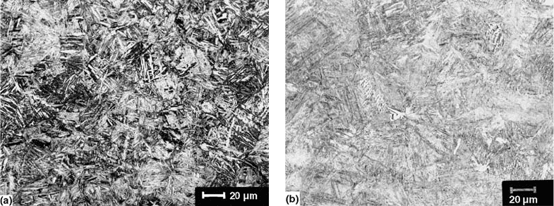
bainite. The appearance of bainite in a carbur-
ized case in even small amounts will sig-
nificantly decrease fatigue strength, especially
contact fatigue strength. It is an important
microstructural defect to be avoided. The pre-
sence of bainite in the carburized case is
particularly problematic because it cannot be
detected by hardness measurements and by the
severity of the quenchant used to harden the steel
after carburizing. Figure 38(a) illustrates a bai-
nitic case microstructure of carburized SAE
8620. Figure 38(b) shows the core structure. In
the case of carbonitrided components, this is less
important because nitrogen increases harden-
ability of steel more than carbon.
Insufficient as-quenched case hardness is
caused by:
Insufficient carbon content in the entire case
or in the superficial zones
Increased retained austenite content
Insufficient case hardenability
Insufficient case depth
On the other hand, core hardness is dependent
on carbon content, steel alloy hardenability, and
section size.
Case carbon content less than 0.4 to 0.5% C is
easily detected by conducting a spark test.
Insufficient case carbon content resulting from
the gas carburizing process occurs when the
process is conducted with a low carbon poten-
tial, inadequate furnace pressure, or cooling the
Sources of Failures in Carburized and Carbonitrided Components / 209
Name ///sr-nova/Dclabs_wip/Failure_Analysis/5113_177-240.pdf/Chap_06/ 18/8/2008 3:19PM Plate # 0 pg 209
load from the diffusion temperature to the
quenching temperature without a protective
atmosphere or improper atmosphere composi-
tion. These problems may be rectified by addi-
tional soaking in a carburizing atmosphere with
the proper carbon potential.
Hardness reduction due to an increase in
retained austenite content may occur with a
direct quenching after the carburizing process.
This is even more critical with steels containing
increased chromium or nickel, which may pro-
duce retained austenite levels as high as 80 to
100% in the surface after quenching. As the case
thickness increases, the zone containing retained
austenite may be sufficient to cause a significant
reduction in hardness. To reduce the retained
austenite content from a direct quenching pro-
cess, it is important to select the proper steel
alloy for carburizing and to use the appropriate
quenchant and quenchant conditions, including
the use of a subzero treatment, if necessary.
Reduced hardenability usually does not occur
throughout the entire case but only in the 0.001
to 0.01 mm depth from the surface. Common
problems leading to reduced hardenability in-
clude internal oxidation and overcarburization
of surface zones. To improve case hardenability,
internal oxidation and overcarburizing should be
prevented.
When the case depth is too shallow, the
observed hardness is dependent on the load
applied. For example, for thicknesses of 0.3
to 0.4 mm, if the surface hardness is deter-
mined using a 60 kg load, the value will be
approximately 12 HRC units higher than if the
hardness is determined using a 150 kg load. In
practice, it is possible for the hardness to differ
by 1 to 2 HRC units from published values for
the material. Hardnesses that are i2 HRC units
less than published values may be due to the use
of an incorrect steel grade or an insufficient
austenitizing temperature for the steel harden-
ability and section size in use. Hardness values
iHRC units higher than published values may
be due to the use of an incorrect steel grade,
excessive case depths, or puncturing a copper
layer or paste on surfaces that are protected from
carburization.
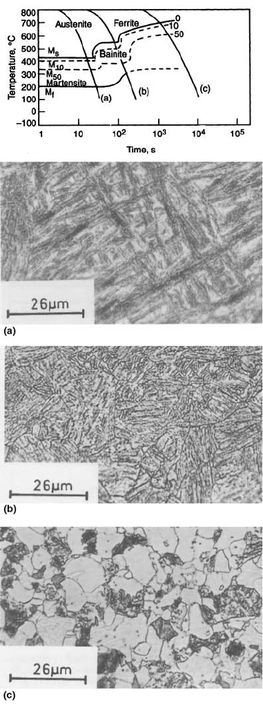
Core Microstructure. The design material
properties of case-hardened steels are not only
dependent on a martensitic case but also on the
microstructural composition of the core. An
important design criterion is the ultimate tensile
strength, which is dependent on the micro-
structure of the core. For example, soft cores
(5770 N/mm
2
, or 50 ton/in.
2
) are suggestive
of a core with high ferrite content, as shown in
Fig. 39(c) (Ref 19), and a hard core (41240 N/
mm
2
, or 80 ton/in.
2
) would be expected for a
predominantly martensitic structure, as shown in
Fig. 39(a) (Ref 19). Intermediate structures
would be bainitic structures, such as those illu-
strated in Fig. 39(b) (Ref 19). The effect of core
microstructure on ultimate tensile strength is
illustrated by Fig. 40 (Ref 90). The approximate
relationship between the core microstructure
and hardness for a Ni-Cr-Mo steel is illustrated
in Fig. 41 (Ref 19).
Fig. 38
The case and core microstructure of carburized SAE 8620 test specimens (0.95% C potential); carburized at 955
C
(1750
F), quenched into a 50:50 mixture of sodium nitrate and potassium nitrate at 250
C (480
F), held 120 min, then air
cooled and tempered at 250
C (480
F) for 240 min. The case is lower bainite (56 HRC), and the core (42 HRC) is lath martensite. These
images were made by etching with 10% Na
2
S
2
O
5
(sodium metabisulfite). The magnification bar is 20 mm. Courtesy of G. Vander Voort,
Buehler Ltd., Lake Bluff, IL
210 / Failure Analysis of Heat Treated Steel Components
Name ///sr-nova/Dclabs_wip/Failure_Analysis/5113_177-240.pdf/Chap_06/ 18/8/2008 3:19PM Plate # 0 pg 210
Influence of the Transition Zone. There
is a transition zone between the case and the
core, and the thickness of a transition zone is
dependent on carburizing time (transition zone
thickness increases with carburizing time),
carburizing medium, and carburizing tempera-
ture (excessive carburizing temperature will
lead to increased pearlite content in the core).
After subsequent hardening, if there is too great
a transition between the case and the core, there
is increased potential for peeling and chipping,
resulting from the presence of a martensitic
carburized case and an uncarburized core con-
taining sorbite.
Fatigue cracks occur most often in the tran-
sition zone, which subsequently propagate into
the core and into the carburized case. When the
gradient between the case and the core changes
too rapidly, operations such as grinding or
when a component is subjected to bending due
to heavy loadings, could lead to peeling and
chipping failures. For example, deep grinding
could not be performed. Increasing the depth
of the transition zone will increase the strength
of adhesion of the case to the core. Then, if the
transition zone is sufficiently large, deep grind-
ing operations may be performed.
Figure 42 provides the microstructure of
two transition zones. Figure 42(a) illustrates a
gradual transition between the case-core
microstructure. A more rapid transition between
the case-core microstructure is illustrated
in Fig. 42(b). Typically, a transition zone
such as that illustrated in Fig. 42(a) is desired,
since it will exhibit a lesser tendency for chip-
ping.
Influence of Surface Carbon Content
Overcarburizing or Overcarbonitriding.
Important microstructural defects related to
carburized or carbonitrided case structure
include overcarburization or overcarbonitriding
of the case and coarse grain structure. Excessive
carbon content (carburizing) or carbon and
nitrogen (carbonitriding) is typified by the pre-
sence of carbides or carbonitrides in the case,
which creates an almost continuous nonetching
area. Case-hardened steels with these micro-
structures characteristically exhibit increased
brittleness, a propensity for chipping during
grinding and use, and decreased fatigue strength
and pitting resistance.
Fig. 39
Microstructures obtained by cooling a 0.16%C-
3%Ni-Cr steel from 920
C. (a) Fast cool (920–
200
C in 30 s), giving low-carbon martensitic structure of
1590 MPa ultimate tensile strength (UTS). Original magnifica-
tion: 800· . (b) Intermediate cooling (920–250
C in 200 s),
giving bainitic structure of 1360 MPa UTS. Original magnifica-
tion: 800· . (c) Slow cool (920–250
C in 104 s), giving a ferrite/
pearlite structure of 740 MPa UTS. Original magnification:
800·
Sources of Failures in Carburized and Carbonitrided Components / 211
Name ///sr-nova/Dclabs_wip/Failure_Analysis/5113_177-240.pdf/Chap_06/ 18/8/2008 3:19PM Plate # 0 pg 211
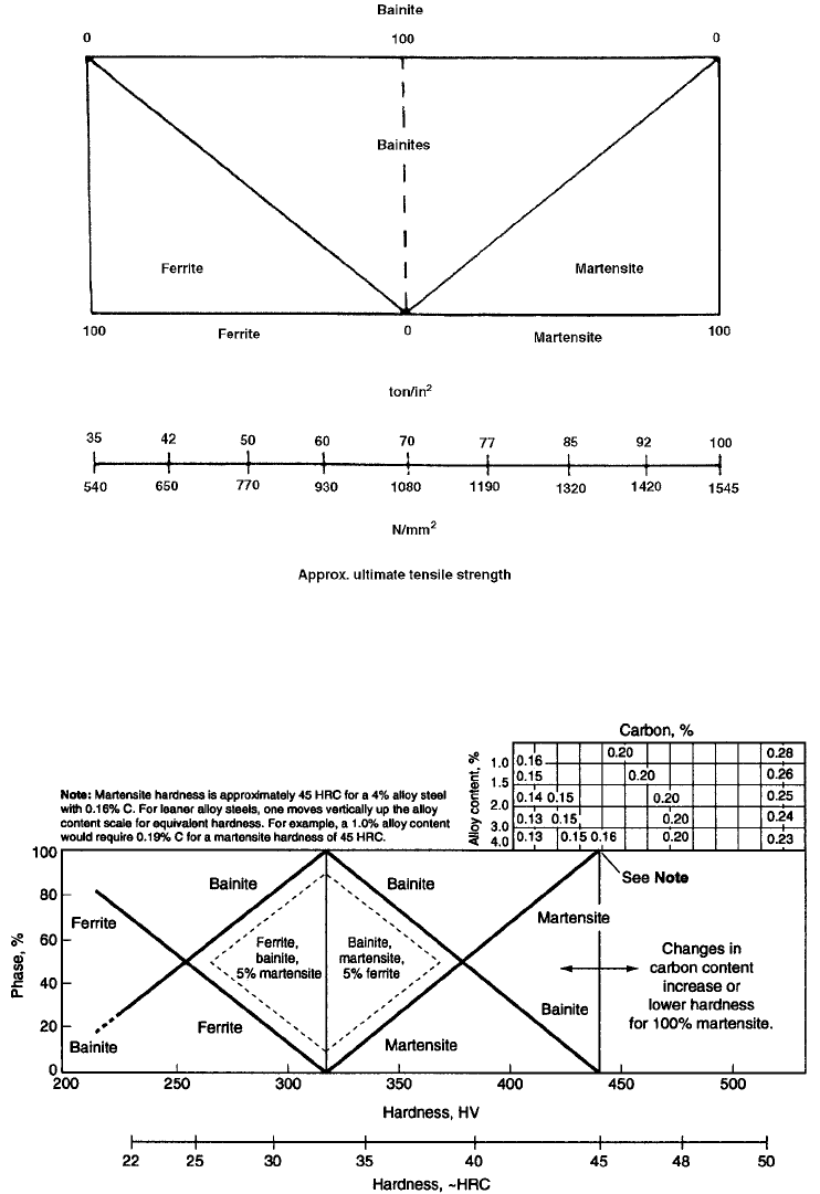
Fig. 40 Approximate effect of microstructure on the ultimate tensile strength of low-carbon, low-alloy steels
Fig. 41
Approximate relationship between core microstructure and hardness of a Ni-Cr-Mo carburizing steel (approximately 4%
alloy content) with approximately 0.16% C. The alloy content/carbon content extension (upper right corner of the figure)
permits phase percentage plots to be adjusted in relation to the fixed hardness scale to approximate core strength for other steels. Below
250 HV represents slow-cooled (normalized) and annealed steels, and bainite can be read as bainite, pearlite, or spheroidized carbides.
Above 250 HV refers to quenched steels. For the 180
C tempered condition, there will be zero change at 360 HV and below, but there
will be a 20 HV loss at 100% martensite.
212 / Failure Analysis of Heat Treated Steel Components
Name ///sr-nova/Dclabs_wip/Failure_Analysis/5113_177-240.pdf/Chap_06/ 18/8/2008 3:20PM Plate # 0 pg 212
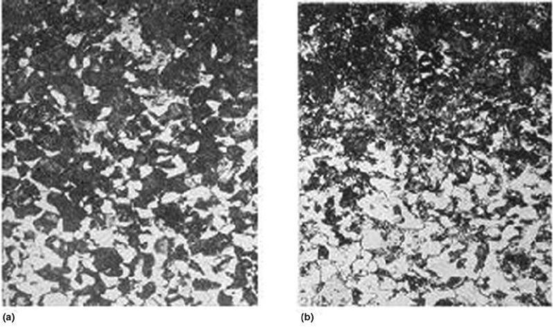
Figure 43 illustrates the effect of carbon
content on the hardness of martensite in carbon
and alloy steels. Increasing carbon content to
0.5% increases hardness from 20 to 65 HRC.
However, increases in carbon content to ap-
proximately 1% do not produce a corresponding
increase in hardness above 65 HRC.
Hardness and mechanical properties are
related not only to carbon content but also the
composition of carburized steels, which is illu-
strated in Fig. 44. This figure shows the corre-
sponding carbon gradients of the cases of three
carburized steels: chromium-molybdenum, car-
bon, and nickel (Ref 25). The data in Fig. 44
show that the presence of chrome and molyb-
denum increases the case carbon content, and
nickel decreases the case carbon content. The
case carbon content is increased due to the pre-
sence of carbide-forming elements; their struc-
tures in the carburized case influence the
mechanical properties of the steel. Over-
carburization may also lead to quench cracking
(Ref 91).
The influence of steel composition on the
microstructure of a carburized and quenched
20H steel is shown in Fig. 45. Figure 45(a) shows
a martensite-retained austenite microstructure
with some carbides dispersed throughout the
structure. Fig. 45(b) shows a martensitic-
retained austenite structure with network car-
bides. This structure is due to the chrome content
in the steel and leads to varying carbon content
during carburizing. Additional examples of the
case microstructure of SAE 8620 steel and core
microstructures of SAE 1524 and 8115 steel are
shown in Fig. 46 to 48 respectively.
Decarburization is the opposite of carbur-
izing. While carburization is performed to
increase carbon content in the surface of steel,
decarburization is the process by which carbon
is lost from the surface of steel. Decarburization
can lead to catastrophic failures of components
(Ref 92) and must be minimized because of
fatigue failure such as bending and contact
fatigue (Ref 93). Figure 49 illustrates decarbur-
ization of a poorly carburized SAE 8620 steel,
and Fig. 50 shows the microstructure at higher
magnification.
Decarburization occurs at temperatures in
excess of 700
C in the presence of gases that act
as decarburization agents, which include carbon
dioxide (CO
2
), water vapor (H
2
O), hydrogen
(H
2
), and oxygen (O
2
). The decarburization
process involves the following chemical
reactions of molecules with carbon in the steel
surface (C
Fe
) until there is an equilibrium
Fig. 42
Micrographs illustrating transition zones between the carburized case and the uncarburized core. (a) Illustrates a gradual
transition. (b) Illustrates a rapid transition between the case and the core microstructures. Original magnification: 500·
Sources of Failures in Carburized and Carbonitrided Components / 213
Name ///sr-nova/Dclabs_wip/Failure_Analysis/5113_177-240.pdf/Chap_06/ 18/8/2008 3:20PM Plate # 0 pg 213