Zuo-Guang. Ye Advanced Dielectric Piezoelectric and Ferroelectric Materials: Synthesis, Characterisation and Applications
Подождите немного. Документ загружается.

Handbook of dielectric, piezoelectric and ferroelectric materials990
Film permittivity
500040003000200010000
1.25
1.20
1.15
1.10
1.05
1.00
Normalized capacitance
Normalized capacitance
1.03
1.02
1.01
1.00
Film permittivity
900700500300
Farnell_5um
EM_10um
Farnell_10um
EM_5um
Farnell_5um
EM_5um
Farnell_10um
EM_10um
EM_25um
EM_50um
32.13
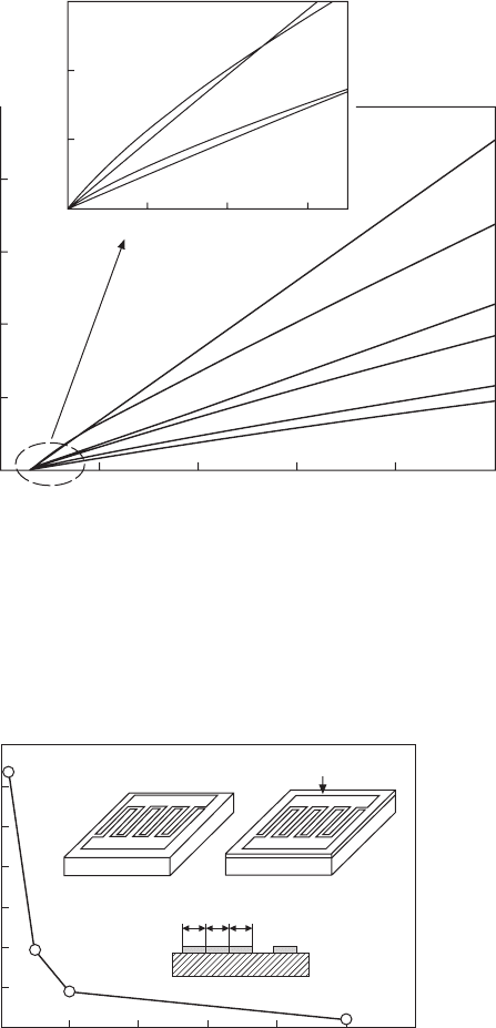
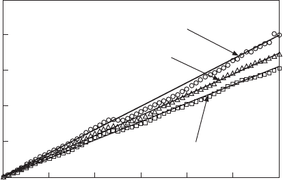
Capacitance variation with film permittivity and the finger
width of interdigital electrodes calculated using Farnell’s theory and
EM analysis. Capacitance in the
y
-axis is normalized to the
capacitance calculated for substrate only (without the film). The
notation of Farnell_5um, for example, means the capacitance
calculated from the Farnell’s theory for interdigital electrodes with a
finger width of 5µm.
DDD
Thin film
Y
t
Y
s
SrTiO
3
substrate SrTiO
3
substrate
Finger width
D
(µm)
6050403020100
0.14
0.12
0.10
0.08
0.06
0.04
0.02
0.00
∆
Y
= (
Y
t
–
Y
s
)
Y
s
32.14
Change of ∆
Y
= (
Y
t
–
Y
s
)/
Y
s
with the finger width
D
of
interdigital electrodes obtained by the EM analysis.
Y
s
is the
admittance of only substrate (ε
s
= 300) and
Y
t
is the admittance of a
film (30nm, ε = 1000) with substrate.
WPNL2204
Dielectric and optical properties of perovskite 991
Another problem in the dielectric measurement of superlattices is the
anisotropy of dielectric properties. The crystal lattices in the superlattices
are distorted in one direction as shown in Fig. 32.8, indicating that the
dielectric permittivity along the film plane (ε
a
) and that along the film thickness
(ε
c
) must be different. Figure 32.16 shows the variation of admittance with
the number of fingers in the interdigital electrodes (Fig. 32.15) obtained by
the EM analysis. In this analysis, the relative dielectric permittivity along the
film plane (ε
a
) was fixed at 5 × 10
5
and that along the film thickness (ε
c
) was
changed from 1.0 × 10
5
to 7.5 × 10
5
. The values of admittance calculated are
identical in spite of the variation of ε
c
as shown in Fig. 32.16, leading to a
very important conclusion that the permittivity measured for superlattices
using interdigital electrodes in Fig. 32.15 is the permittivity along film plane
(ε
a
) of the superlattices.
32.5.2 Dielectric property
Dielectric permittivity of BTO/STO superlattices
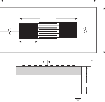
The interdigital electrodes shown in Fig. 32.15 were formed on the film
surface using electron beam lithography. The admittance between the
fingers of the interdigital electrodes was measured using impedance
analyzer (HP4294A) connected to a micro-prober system (Measure Jigu,
WN365A1).
300mm
305µm
Thin film
300mm
Port 2
100µm
Port 1
Pt
electrode
5µm
32nm
0.5mm
Thin film
SrTiO
3
substrate
ε
r
= 300
32.15
Final design and the model of the EM analysis of interdigital
electrodes on superlattice films.
WPNL2204
Handbook of dielectric, piezoelectric and ferroelectric materials992
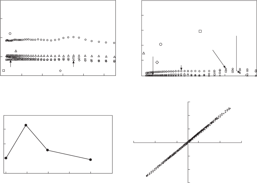
The dielectric properties of BTO/STO superlattices are shown in Fig.
32.17. The frequency dispersion of capacitance (Fig. 32.17a) indicates that
the capacitance (dielectric permittivity) of the BTO/STO superlattices does
not depend on frequency significantly and that the permittivity of [BTO
10
/
STO
10
]
4
superlattice is much higher than that of other superlattices. The
dielectric loss tangents of all superlattices are several % or less (Fig. 32.17b).
The dielectric permittivity of superlattices was calculated by fitting admittance
calculated with the EM analysis to that observed. The EM analysis was
repeated with changed permittivity of the superlattices until the best fit was
obtained. The dielectric permittivity so obtained for the BTO/STO superlattices
at 110 MHz is shown as a function of the stacking periodicity of the superlattices
in Fig. 32.17(c). The BTO/STO superlattice with the stacking period of 10
unit cells of perovskite lattice shows the highest permittivity of 33 000
which is remarkably higher than those reported previously.
10,12
However, the
highest permittivity was very sensitive to the quality of superlattices and it
varied from 16000 to 35000 with a slight variation of the deposition conditions.
The charge (Q) vs. voltage (V) curve of the [BTO
10
/STO
10
]
4
superlattice
measured with the interdigital electrodes at 132.5Hz is shown in Fig. 32.17(d).
A linear relation is observed in the Q – V curve. Bulk ceramics of the BTO–
STO system also exhibit large dielectric permittivity with the relaxor or the
diffuse phase transition behaviors. The high permittivity of the bulk ceramics
is accompanied with the nonlinearity of the dielectric permittivity, and it can
be explained by the electric-field-induced orientation of thermally fluctuating
Interdigital electrodes
with finger number 5
Number of fingers
151311579
3.0
2.5
2.0
1.5
1.0
0.5
0.0
Admittance (
S
) × 10
–4
)
Substrate
ε
c
ε
a
Thin film
ε
a
= 5 × 10
5
ε
c
= 10 × 10
5
– 7.5 × 10
5
32.16
Admittance as a function of the number of fingers in
interdigital electrodes obtained by the EM analysis. In the analysis,
the permittivity along the film plane (ε
a
) was fixed at 5 × 10⁵ but that
along the film thickness (ε
c
) was varied from 1.0×10⁵ to 7.5 × 10⁵. The
admittance is independent of ε
c
.
WPNL2204
Dielectric and optical properties of perovskite 993
Frequency (MHz)
(b)
100800604020
Tan δ
1.0
0.8
0.6
0.4
0.2
0.0
[BTO
1
/STO
1
]
40
[BTO
10
/STO
10
]
4
[BTO
40
/STO
40
]
1
[BTO
20
/STO
20
]
2
Stacking periodicity
(c)
403020101
Relative permittivity
40000
30000
20000
10000
0
(d)
–75
–50
–25
25
50
75
Charge (µQ)
–25 –15 –5 501525
Voltage (V)
[BTO
10
/STO
10
]
4
Frequency (MHz)
(a)
0 20 40 60 80 100
[BTO
10
/STO
10
]
4
[BTO
20
/STO
20
]
2
[BTO
1
/STO
1
]
40
[BTO
40
/STO
40
]
1
Capacitance (pF)
4.0
5.0
3.0
2.0
1.0
32.17
Dielectric properties of BTO/STO superlattices: (a) frequency dispersion of capacitance; (b) frequency dispersion of
loss tangent; (c) relative dielectric permittivity at 110 MHz as a function of stacking periodicity of superlattices; (d)
charge vs. voltage curve of [BTO10/STO10]4 superlattices.
WPNL2204
Handbook of dielectric, piezoelectric and ferroelectric materials994
spontaneous polarization in the polar nano-regions. This type of dipole
polarization always shows nonlinear dielectricity and dielectric dispersion at
relatively low frequencies. However, the high permittivity of the superlattices
does not show any nonlinear behaviors, as shown in Fig. 32.17(d) and the
dielectric relaxation is not observed at frequencies up to 110MHz. We think
that this is a truly remarkable and anomalous dielectric behavior of the
superlattice.
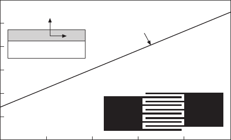
The enhancement of the permittivity was also confirmed in the BTO/STO
superlattices prepared with the RF-magnetron sputtering system shown in
Fig. 32.5(b). The admittances measured with a planar electrode on the [BTO
10
/
STO
10
]
4
superlattices and on the Ba
0.5
Sr
0.5
TiO
3
thin film are shown in Fig.
32.18 as a function of frequency. The planar electrode was designed to
contact a ground–source–ground three terminal probe (Cascade Microtech.)
for high-frequency measurements. The straight lines to fit the experimental
data in Fig. 32.18 were obtained from the EM-analysis. The relative permittivity
of the [BTO
10
/STO
10
]
50
superlattices deposited at 600°C was determined to
be 850, which was much higher than that of the Ba
0.5
Sr
0.5
TiO
3
thin film
deposited at 750°C (ε
r
= 280). The relative permittivity of the [BTO
50
/STO
50
]
10
superlattices was about 750, which was lower than the superlattice with the
periodicity of 10. These results are consistent with those obtained for
superlattices made with the MBE system, indicating that the formation of
superlattices enhanced the permittivity and the degree of enhancement is
enlarged in the superlattices with the periodicity of 10. It is also an important
and anomalous behavior that the superlattice film deposited at a higher
temperature of 650°C showed a lower permittivity (ε
r
= 510) than that
deposited at 600°C (ε
r
= 850). This phenomenon can be interpreted by
Frequency (GHz)
2.5 3.02.01.51.00.50.0
10.0
8.0
6.0
4.0
2.0
0.0
Admittance (
S
) × 10
–3
Ba
0.5
Sr
0.5
TiO
3
film at 750°C (ε
r
= 280)
[BTO
10
/STO
10
]
50
at 650°C (ε
r
= 510)
[BTO
10
/STO
10
]
50
at 600°C (ε
r
= 850)
32.18
Admittance of BTO/STO superlattices and Ba
0.5
Sr
0.5
TiO
3
thin
film as a function of frequency. The solid lines were obtained by the
EM analysis.
WPNL2204
Dielectric and optical properties of perovskite 995
taking into account an interdiffusion of Ba and Sr at the boundary of each
layer during the deposition at high temperatures. Although the enhancement
of the permittivity was confirmed by the superlattices prepared with a different
deposition process, the permittivity of RF-sputtered superlattices was much
lower than that prepared with the MBE process. This is obviously due to the
imperfection of superlattice structures in the sputter-derived films. We could
not, in fact, observe clear satellite peaks in the XRD analysis of the sputter-
derived films. The enhancement of the permittivity is sensitive to the quality
of superlattices. However, the enhancement of the permittivity in the films
deposited with a simple sputtering process has an important meaning for the
practical applications of perovskite superlattices. Decoupling capacitors on
Si-chips are currently demanded for the noise reduction and the stable electric-
current supply to the LSI circuits. The BTO–STO thin films are regarded as
one of the candidates for this application because of their relatively high
permittivity with low loss, but the permittivity at low deposition temperatures
still need to be enhanced at the present. The formation of superlattice-like
structures using simple sputtering process may give a new solution to satisfy
the requirements to the capacitor films.
Mechanism of permittivity enhancement in BTO/STO superlattices
Although the Maxwell–Wagner effects due to the electric conduction have
been pointed out as a mechanism of dielectric enhancements in oxide
superlattices,
30
we do not think that the anomalous dielectric behavior shown
in Fig. 32.17 is due to these effects because the superlattices showed relatively
low loss tangents, a linear Q–V relation (leakage current gives round shape
in the curve) and dielectric enhancement at high frequencies. It should be also
be noted that the result of dielectric enhancement is consistent with the change
of refractive index (Fig. 32.11) as well as the lattice distortions (Fig. 32.8).
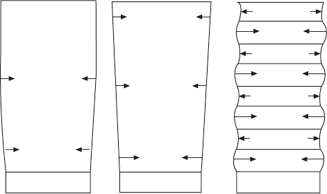
The relaxation of crystal lattices and the stress directions in a BTO film,
a Ba
0.5
Sr
0.5
TiO
3
film and a BTO/STO superlattice on a STO substrate are
depicted in Fig. 32.19. A large in-plane compressive stress is applied to the
BTO films from the substrate because of the lattice mismatch between BTO
and STO. The BTO lattices near the substrate are distorted to elongate its c-
parameter (lattice parameter along the film thickness) while keeping the a-
parameter (lattice parameter along the film plane) to achieve the lattice
matching with the STO substrate. These strained lattices are relaxed with
increasing film thickness by introducing dislocations. The similar stress should
be applied to the (Ba
0.5
Sr
0.5
)TiO
3
film but the stress is lower than the case of
BTO film because of the smaller lattice mismatch between (Ba
0.5
Sr
0.5
)TiO
3
and STO. Therefore, the strained lattices are remained thicker than the case
of the BTO films. In the case of superlattices, the similar compressive stress
is applied to the first BTO layer from the substrate to distort the crystal
WPNL2204
Handbook of dielectric, piezoelectric and ferroelectric materials996
STOSTOSTO
(Ba
0.5
Sr
0.5
)TiO
3
BTO
BTO film Solid solution film Superlattice
BTO
STO
BTO
STO
BTO
STO
BTO
STO
32.19
Models of lattice relaxation and the direction of stresses in
films deposited on STO substrates.
lattices of the BTO, but these strained lattices of BTO are not relaxed because
the next STO layers are deposited on the strained BTO lattices to give a new
compressive stress. Owing to the stress induced by the STO layers in the
superlattices, the strained BTO lattices remain up to the film surface. Although
a large stress and a strain are thus induced into the BTO layers, the stress and
strain in the STO layers in the superlattices should be very small because the
stress is hardly induced to the STO layers from the strained BTO layers or
the STO substrate with the same a-parameter.
The ideal cases of the strained lattice formation are observed in the BTO/
STO superlattice with the periodicity of 10, where the a-parameter of the
superlattice is consistent with that of STO (Fig. 32.8). As the staking periodicity
increases to 40, the strained lattices were relaxed as indicated by the change
in the a-parameter. The elongation of c-parameter of BTO lattice stabilizes
and/or enhances the spontaneous polarization of BTO layers along the film
thickness. It should be recalled that the result of the EM analysis indicated
that the permittivity measured with interdigital electrodes was that along the
film plane. This means that the electric field applied in the dielectric
measurements using interdigital electrodes is perpendicular to the direction
of the spontaneous polarization of BTO layers, which is analogous with the
permittivity measurement of a tetragonal BTO single crystal along its a-axis.
It is known that the permittivity along the a-axis of the tetragonal BTO is
much higher than that along the c-axis because of flat potential wells in the
lattice and/or the rotation of spontaneous polarization with electric fields
which contribute to the dipole polarizations. We believe that this is the
mechanism of the enhancement of dielectric permittivity in the BTO/STO
superlattices formed on the STO substrate. The permittivity observed in our
study was much higher than previously reported because we only used planar
electrodes in the permittivity measurements.
WPNL2204
Dielectric and optical properties of perovskite 997
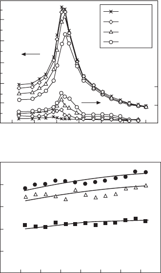
Temperature dependence of permittivity of BTO/STO superlattices
Temperature dependence of the dielectric permittivity provides important
information for understanding the mechanism of the dielectric anomaly of
the superlattices. The high permittivity of BTO-STO ceramics is accompanied
by the phase transition at the Curie point. Even in the relaxors, the formation
of polar nano-regions can be regarded as a precursor phenomenon of the
phase transition. As far as the phase transition is concerned with the generation
of high permittivity, the permittivity inevitably varies with temperature. Figure
32.20(a) shows the complex dielectric permittivity of Ba
0.6
Sr
0.4
TiO
3
ceramics
as a function of temperature.
60
The ceramics show a large permittivity peak
at about 5°C corresponding to the first-order phase transition. The room
temperature permittivity of about 6000 is due to the tailing of the peak,
therefore the temperature stability of high permittivity cannot be expected in
the ceramics. The real dielectric permittivity of the BTO/STO superlattices
1MHz
100MHz
1GHz
3GHz
Temperature (°C)
(b)
160140120100806040200
25000
20000
15000
10000
5000
0
Relative permittivity
[BTO
15
/STO
5
]
4
[BTO
12
/STO
8
]
4
[BTO
10
/STO
10
]
4
Temperature (°C)
(a)
3000
1500
ε″
806040200–20–40
15000
12000
9000
6000
3000
0
ε′
32.20
Temperature dependence of dielectric permittivity;
(a) Ba
0.6
Sr
0.4
TiO
3
ceramics; (b) BTO/STO superlattices.
WPNL2204
Handbook of dielectric, piezoelectric and ferroelectric materials998
with different compositions is shown in Fig. 32.20(b) as a function of
temperature. The permittivity of the [BTO
10
/STO
10
]
4
superlattice is about
19000 at room temperature, which is lower than the result in Fig. 32.17. This
discrepancy is due to the sensitivity of permittivity to the quality of the
superlattices. The dielectric permittivity of the [BTO
10
/STO
10
]
4
superlattices
is higher than other superlattices, namely [BTO
12
/STO
8
]
4
and [BTO
15
/STO
4
]
4
.
Again, the enhancement of the permittivity in the superlattices with a periodicity
of 10 was confirmed. As for the temperature dependence of the permittivity,
the permittivity increases in all superlattices with increasing temperature
and no peak of the permittivity is observed in the temperature range up to
150 °C. These results strongly suggest that the high permittivity of the
superlattices is not concerned with the phase transition but is caused by the
temperature-stable lattice distortions induced by the lattice mismatch between
STO and BTO.
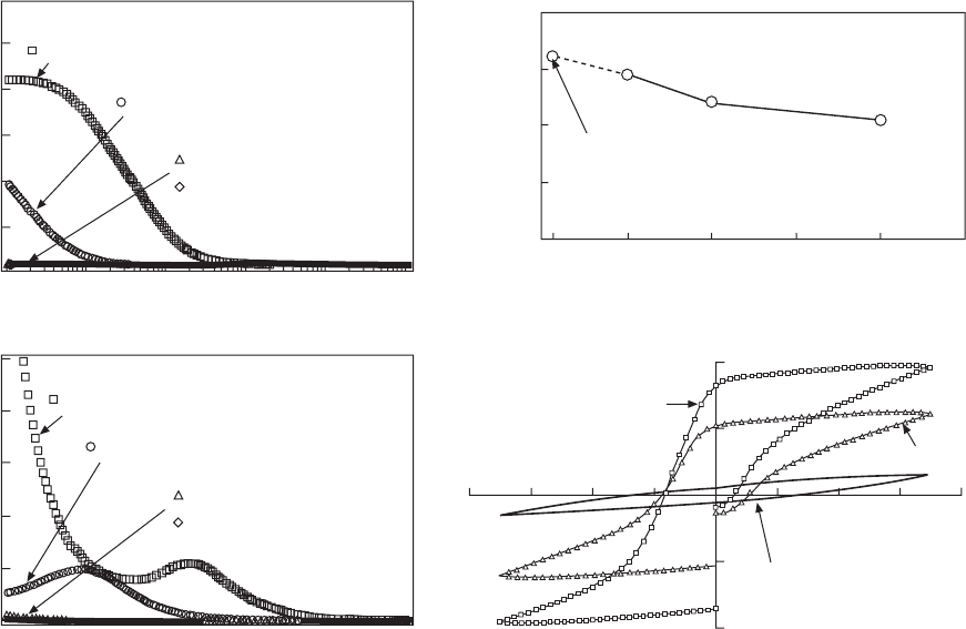
Artificial ferroelectricity in SZO/STO superlattices
61
Figure 32.21(a) and (b) shows capacitances and dielectric loss tangents of
the SZO/STO superlattices. It is notable that a large dielectric relaxation was
observed in the superlattices with the periodicity of 1 and 10, which was not
observed in the BTO/STO superlattices in Fig. 32.17. The dielectric loss
tangent of the [SZO
1
/STO
1
]
40
superlattice steeply increases in the low-
frequency region, which obviously indicates the effect of electric conduction.
This superlattice also shows a high extinction coefficient in the optical
frequencies (Fig. 32.10b). We believe that the high loss and high leakage
current observed only in this superlattice are concerned with overlapping of
electron clouds caused by the lattice shrinkage of this superlattice (see the
result of the XRD analysis in Fig. 32.8b). A dielectric loss peak was also
observed at 250kHz in the [SZO
1
/STO
1
]
40
superlattice. The dielectric loss
peak indicates that a polarizing species with a relatively long relaxation time
exists in this superlattice. A similar dielectric loss is observed in the [SZO
10
/
STO
10
]
4
superlattice but its frequency is lower than that of the [SZO
1
/STO
1
]
40
superlattice. The dielectric loss of the [SZO
20
/STO
20
]
2
superlattice slightly
increases in the low-frequency region. This may be due to the tailing of the
dielectric loss peak at lower frequencies. The peak frequency seems to decrease
with increasing periodicity of superlattices.
The variation of the relative permittivity at 110 MHz with the periodicity
of superlattices is shown in Fig. 32.21(c). The permittivity of the superlattice
with a periodicity of 1 is not reliable because of its high leakage current. The
permittivity decreased with increasing periodicity over the periodicity of 10,
which is similar to the behavior of the BTO/STO superlattices, but the maximum
permittivity of the SZO/STO superlattices is lower that of the BTO/STO
superlattices (Fig. 32.17c).
WPNL2204
Dielectric and optical properties of perovskite 999
32.21
Dielectric properties of SZO/STO superlattices: (a) frequency dispersion of capacitance; (b) frequency dispersion of
loss tangent; (c) relative dielectric permittivity at 110MHz as a function of stacking periodicity of superlattices;
(d) Charge vs. voltage curve.
Dielectric permittivity
20000
15000
10000
5000
0
Conductive
Stacking periodicity
(c)
403020101
(d)
–200
200
–8 –6 –4 –2
2468
Voltage (V)
[SZO
40
/STO
40
]
1
[SZO
10
/STO
10
]
4
Charge (µQ)
Frequency (Hz)
(b)
10
8
10
3
10
4
10
5
10
6
10
7
Tan δ
10
8
6
4
2
0
[SZO
20
/STO
20
]
2
[SZO
40
/STO
40
]
1
[SZO
1
/STO
1
]
40
[SZO
10
/STO
10
]
4
Frequency (Hz)
(a)
10
8
10
3
10
4
10
5
10
6
10
7
Capacitance (pF)
60
50
40
30
20
10
0
[SZO
40
/STO
40
]
1
[SZO
20
/STO
20
]
4
[SZO
10
/STO
10
]
4
[SZO
1
/STO
1
]
40
[SZO
20
/STO
20
]
2
WPNL2204