Teodorescu P.P. Mechanical Systems, Classical Models Volume I: Particle Mechanics
Подождите немного. Документ загружается.

MECHANICAL SYSTEMS, CLASSICAL MODELS
260
obviously, it is necessary to specify also some laws of variation of those efforts. To do
this, we consider an element of the bar axis of length
ds , reducing thus all the forces
with respect to the axis’ points, corresponding to the cross sections on which act these
forces; as well, we suppose that the bar is acted upon only by distributed forces
pds
and by distributed moments
mds , for which
=++p ppp
τν
β
τνβ,
=
++m
t
mm m
ν
β
τ
νβ. (4.2.35')
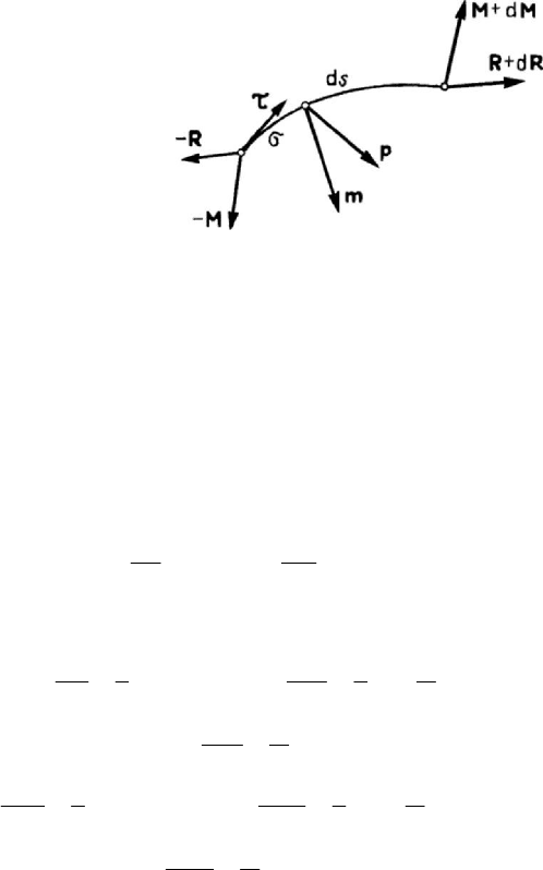
Figure 4.34. Equilibrium of an element of bar.
Equating to zero the torsor of all the forces which act upon this bar element (Fig.4.34),
we obtain
−
++ + =RR Rp 0(d)ds ,
−+ + + + × + + × =
∫
MM Mm R R p 0
d
0
(d)d(d)(d) ()()d
s
ss σσσττ.
Applying a mean value formula to the above integral and neglecting the terms of higher
order, there results
+=
R
p0
d
ds
,
+
×+ =
M
Rm 0
d
ds
τ .
(4.2.36)
Taking into account Frenet’s formulae given in Subsec. 1.1.3, we get
−+=
d1
0
d
N
Tp
s
ντ
ρ
,
+
++=
′
d11
0
d
T
NTp
s
ν
ν
β
ρρ
,
−
+=
′
d
1
0
d
T
Tp
s
β
ν
β
ρ
,
(4.2.37)
d
1
0
d
t
M
Mm
s
ντ
ρ
−+=,
d1 1
0
d
t
M
MMTm
s
ν
ν
ββ
ρρ
+
+−+=
′
,
−
++ =
′
d
1
0
d
M
MTm
s
β
νν
β
ρ
.
(4.2.37')
With the aid of the first two equations (4.2.37) one can express the efforts
T
ν
and T
β
as functions of the given external loads and the normal force
N ; replacing in the third
Statics
261
equation, we get a differential equation of the third order in
N , which may determine
the latter effort. Analogously, the equations (4.2.37') lead to a differential equation of
the same order for the moment of torsion
t
M which contains the axial force N too,
now known; we mat determine thus all six efforts.
In the case of a plane curved bar
′
→1/ 0ρ ,
β
being the unit vector normal to the
plane of the bar; we get
−+=
d1
0
d
N
Tp
s
ντ
ρ
,
+
+=
d1
0
d
T
Np
s
ν
ν
ρ
,
+
=
d
0
d
T
p
s
β
β
,
(4.2.38)
d
1
0
d
t
M
Mm
s
ντ
ρ
−+=,
d1
0
d
t
M
MT m
s
ν
ν
β
ρ
+
−+ =,
+
+=
d
0
d
M
Tm
s
β
ν
β
.
(4.2.38')
One of the efforts
N and T
ν
may be eliminated between the first two equations
(4.2.38), obtaining thus a differential equation of the second order in the other effort;
the third equation allows the computation of the shearing force
T
β
. These efforts being
obtained, one can make analogous considerations for the subsystem (4.2.38').
If the plane curved bar is acted upon by forces contained in its plane, then one has
= 0p
β
, ==0mm
τν
, and, taking into account the Theorem 4.2.4 (the resultant of
the external forces is contained in the plane of the bar axis, while the resultant moment
of these forces is normal to this plane) one gets
=
0T
β
,
=
= 0
t
MM
ν
too; the
remaining equations are
−+=
d1
0
d
N
Tp
s
ντ
ρ
,
+
+=
d1
0
d
T
Np
s
ν
ν
ρ
,
+
+=
d
0
d
M
Tm
s
β
ν
β
,
(4.2.39)
and one makes observations analogous to those above.
If the plane curved bar is acted upon by forces normal to its plane, then we have
==0pp
τν
, = 0m
β
, and, on the basis of the same theorem (the external forces
constitute a system of parallel forces), we obtain
=
0N ,
=
0T
ν
, = 0M
β
; the
system of equations becomes
+=
d
0
d
T
p
s
β
β
,
d
1
0
d
t
M
Mm
s
ντ
ρ
−+=,
d1
0
d
t
M
MT m
s
ν
ν
β
ρ
+
−+ =, (4.2.40)
and may be analogously studied.
Starting from the two particular cases considered above, we obtain the solution
corresponding to the general case, by superposing the effects.
In the case of straight bars, the direction of the binormal and the direction of the
principal normal are not determined; it is convenient to use a right-handed fixed
orthonormed frame of reference
123
Ox x x
, the axis
3
Ox
being along the bar axis
MECHANICAL SYSTEMS, CLASSICAL MODELS
262
(
→1/ 0ρ and =
3
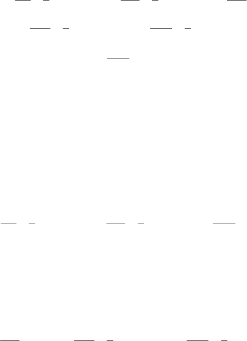
ddsx). Corresponding to the conventions in technical mechanics
of deformable solids (strength of materials), the components of the torsor of internal
forces are of the form (Fig.4.35,a,b)
Figure 4.35. Efforts on a cross section of a straight bar: force components (a)
and moment components (b).
=− + +Riii
21 12 3
TTN,
=
++Mi i i
11 22 33
MMM, (4.2.41)
and the external load is given by
=
pi
j
j
p ,
=
mi
j
j
m , (4.2.41')
where
i
j
,
=
1, 2, 3j
, are the unit vectors of the co-ordinate axes. We obtain the
relations
+=Rp0
,3
,
+
×+ =MiRm0
,3 3
(4.2.42)
or, in components,
−=
2,3 1
0Tp ,
+
=
1,3 2
0Tp ,
+
=
,3 3
0Np , (4.2.42')
−
+=
1,3 1 1
0MTm ,
−
+=
2,3 2 2
0MTm ,
,3 3
0
t
Mm
+
= . (4.2.42'')
Eliminating the shearing forces, we get
++=
1,33 1,3 2
0Mmp,
+
−=
2,33 2,3 1
0Mmp. (4.2.43)
In the case of external loads contained in the plane
13
Ox x , we have =
2
0p ,
==
13
0mm ; there results
=
1,3
0T ,
−
=
1,3 1
0MT ,
,3
0
t
M
=
,
Statics
263
wherefrom
==
0
11
constTT , =+
00
113 1
MTxM, =
0
1
constM ,
0
const
tt
MM==
(4.2.44)
and
=
2,3 1
Tp,
=
−
2,3 2 2
MTm,
=
−
2,33 1 2,3
Mpm. (4.2.44')
If we have too
=
2
0m , then we may write
=
2,3 1
Tp,
=
2,3 2
MT, (4.2.45)
so that
=
2,33 1
Mp. (4.2.45')
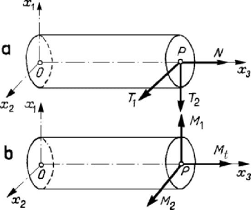
In this case, the diagrams of efforts are, e.g., (Fig.4.36), where we have put into
evidence the correspondence between the point of extremum for the bending moment
and the point at which the shearing force vanishes; we notice also the correspondence
between the inflexion point of the diagram of bending moments, the point of extremum
of the diagram of shearing forces and the point at which the diagram of normal loadings
vanishes, as well as the correspondence between the point of inflexion of the diagram of
shearing forces and the point of extremum of the diagram of normal loadings.
Sometimes, the positive part of the diagram of bending moments is plotted under the
axis (to be in concordance with the deflection line of the bar axis).
Figure 4.36. Diagrams of efforts in a straight bar acted upon by loads in a plane.
In the case of loads contained in the plane
23
Ox x (
=
1
0p ,
=
=
23
0mm ) we can
make analogous observations.
We notice that, in all considerations made in this subsection, the bar is reduced to
its axis; as a matter of fact, so it is for all problems concerning the efforts on the
cross section. This is a mathematical model, which is used currently in technical
mechanics of solids.
MECHANICAL SYSTEMS, CLASSICAL MODELS
264
In the case of external concentrated loads (e.g., concentrated forces), the above
relations remain valid if the usual functions are replaced by distributions, the operations
of differentiation being effected in the same sense too. For instance, in the case of a
straight bar acted upon by a concentrated force
()
(
)
=δ −
0
13 3 3
px P x x
(4.2.46)
at the point of co-ordinate
0
3
x , the equations (4.2.45) lead to
()
(
)
00
23 3 3 2
Tx P x x Tθ=−+,
()
()
(
)
0000
23 3 3 3 3 23 2
Mx Px x x x Tx Mθ=− −++
;
(4.2.46')
the shearing force and the bending moment at the cross section
=
3
0x are thus put in
evidence.
2.1.8 Articulated systems
An articulated system is a structure of bars (a system of rigid solids) linked by
articulations, so as to form a non-deformable system from a geometric point of view (not
a mechanism); the loads are supposed to be applied at the nodes.
By definition, for a bar between two articulations, all the given and constraint forces,
can be reduced to resultants at each extremity of it; for equilibrium, the two resultants
must be directed along the straight line connecting the articulations, having the same
modulus and opposite directions. Hence, from a statical point of view, a bar requires
only one unknown: the corresponding axial force.
The theoretical articulations at the nodes cannot be practically realized. The nodes
are more or less rigid in the case of constructions in concrete or metal; these rigidities
introduce secondary efforts, which may be computed separately. As well, if the bars are
acted also transversally (for instance, by their own weight), one calculates the resultants
at the nodes, while the effect of the other efforts (for instance of bending) are separately
computed.
Starting from the most simple non-deformable geometric construction formed by
articulated bars (the triangle, which has three nodes and three bars), one can constitute a
plane articulated system. By complete induction, one can show that between the number
b of bars and the number n of nodes takes place the relation
=
+23nb , (4.2.47)
which represents a necessary condition for the geometric non-deformability of the plane
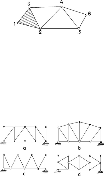
articulated system; thus, a plane articulated system 1-2-…-6, constructed starting form a
basic triangle 1-2-3, is shown in Fig.4.37. On the other hand, a system must be
analysed, from case to case, to see if it is not a system of critical form (at least partially),
the form of which may be lost under the action of a particular system of external loads;
we will not deal with such articulated systems.
Statics
265
A free articulated system, as that considered above, can be fixed in its plane with the
aid of three simple constraints (a hinge and a simple support or three simple supports of
non-concurrent directions at the nodes. Because a simple support is equivalent to a
pendulum (a bar), the relation (4.2.47) has the more general form
Figure 4.37. The setting up of a plane articulated system.
=
+2nbs, ≥ 3s , (4.2.47')
where
s is the number of simple supports. If
=
3s , then the plane articulated system
(structure) constitutes a single geometrically non-deformable body, by suppressing the
supports, and is called a free articulated system (structure).
If we are isolating each node (sectioning all the bars around the node), then the given
and the constraint forces, as well as the efforts in bars form a system of concurrent
forces; writing two equations of equilibrium for each node we obtain
2n equations. If
the relation (4.2.47') holds, then the articulated system is statically determinate (on the
basis of the Kronecker-Capelli theorem for systems of linear algebraic equations); if
<+2nbs, then the articulated system is statically indeterminate, while if
>+2nbs, then the system is a mechanism (geometrically deformable).
Figure 4.38. Rectangular system (a), trapezoidal system (b), triangular system (c)
and
K
lattice (d) framework.
A plane articulated system may – often – play, in its totality, the rôle of a bar, which
is called truss (framework). The bars of the contour (excepting the lateral ones) are
called flanges; according to their positions, we distinguish between superior and
inferior flanges. The bars linking the flanges are called members (lattices); the vertical
lattices are called vertical members, while the inclined ones are called diagonals. We
denote the axial force in the bar of the framework by
,,SIV or D if this one is a
superior or inferior flange, a vertical member or a diagonal, respectively. According to
MECHANICAL SYSTEMS, CLASSICAL MODELS
266
the form of the contour, the frameworks may be frameworks with parallel flanges
(Fig.4.38,a) or frameworks with polygonal flanges (Fig.4.38,b).
Among the simple articulated systems, we mention: rectangular system trusses
(Fig.4.38,a), trapezoidal system trusses (Fig.4.38,b), triangular system trusses
(Fig.4.38,c) and
K lattice trusses (Fig.4.38,d). If over a primitive system of bars is
introduced a supplementary system, then one obtains a compound articulated system.
The double rectangular system trusses, the double triangular system trusses or the
trusses with multiple lattices form complex articulated systems.
To determine the efforts in the bars of a framework, one may use various methods of
computation. Thus, in the method of sections (Ritter’s method) a complete section is
made, and the conditions of equilibrium of one of the two parts are put. Only three
unknowns may appear, because one can write only three equations of equilibrium; if the
reactions have been previously obtained, then the unknowns may be only efforts in the
sectioned bars, so that these ones cannot be more than three. We notice that these bars
must not be all concurrent or parallel; in such a case, the three equations are no more
linearly independent.
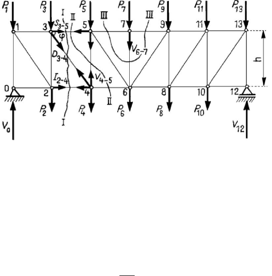
Figure 4.39. Equilibrium of a framework with parallel flanges.
Let be a framework with parallel flanges (Fig.4.39), of height
h
, acted upon by
vertical concentrated forces at the nodes. Because the truss is simply supported, the
reactions can be obtained from its global equilibrium, as in the case of a usual straight
bar. Let thus be a section I-I; we replace the sectioned bars (3-5, 2-4 and 3-4) by the
corresponding efforts (
35
S
−
,
24
I
−
and
34
D
−
), with a positive sign. We consider the
equilibrium of the left part of the truss. The equation of moment with respect to the
node 3 leads to
3
24
M
I
h
−
=
,
(4.2.48)
where
3
M is the moment of the given and constraint forces acting upon the left part of
the bar with respect to the node 3 (positive if the corresponding couple leads to a
clockwise rotation in the plane); analogously, the equation of moment about the node 4
allows to write
Statics
267
4
35
M
S
h
−
=− ,
(4.2.48')
where
4
M
has a similar signification. The equation of projection on the normal
common to the two parallel flanges yields
1
34
sin
T
D
ϕ
−
= ,
(4.2.48'')
where
1
T is the projection on the considered direction of all the given and constraint
forces at the left of section I-I, while
ϕ is the angle formed by the diagonal with one of
the flanges. We notice that
M and T have the significance of a bending moment and
of a shearing force in a straight bar, respectively, their sign being analogously
established. In the case of a section II-II, the equation of projection on the normal
common to the parallel flanges leads to
II45
VT
−
=
, (4.2.49)
where
II
T has an analogous significance. One obtains thus the efforts in all the bars of
the framework. Only for the vertical member 6-7 one must make a section of the form
III-III (we isolate the node 7), wherefrom
67 7
VP
−
=
−
. (4.2.50)
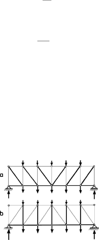
Figure 4.40. Framework with tensioned (a) or compressed (b) diagonals.
Such a bar for which the effort depends only on a local load, being independent of the
form of the beam and of its loading, is called a supplementary bar.
As we can see, it follows that in the bars of the superior flanges and in the vertical
beams appear only efforts of compression, while in the bars of the inferior flanges and
in the diagonals we have efforts of tension. The compressed bars are traced by thin
lines, while the tensioned ones are traced by thick lines (Fig.4.40,a). If the diagonals
of each pane would be ascendent towards the middle of the truss (instead to be
MECHANICAL SYSTEMS, CLASSICAL MODELS
268
descendent, as in the previous case), then they would be compressed and the vertical
members tensioned, but the bars of the flanges would have efforts of the same sign as
above. These results are rendered by the same graphical convention in Fig.4.40,b; we
notice that the efforts in the superior flanges of the panes and in the end vertical
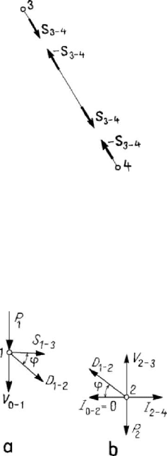
members vanish. Indeed, these affirmations are justified because between the efforts in
the bars and the forces acting at the nodes take place relations of the type of those
between the internal forces (see, e.g., the nodes 3 and 4 and the bar 3-4, Fig.4.41).
This method of computation may be applied analogously in the case of a truss with
polygonal flanges; we mention that it can be used in a graphical variant too.
Another method of computation often used is the method of isolation of nodes, which
is – in fact – a particular case of the method of sections; in the frame of this method,
each node is isolated, by sectioning the bars which start form this one and by replacing
them by the corresponding efforts. One obtains thus, in each node, a system
Figure 4.41. Efforts in the members of a framework.
of forces which must be in equilibrium. Two equations can be thus written for each
node; this method of computation is convenient if we can solve these equations for each
node separately. We start from a node where intervene only two unknowns, passing
than to neighbouring nodes where intervene only two unknowns too. For instance, in
the case of the truss with parallel flanges considered in Fig.4.39 one starts from the
Figure 4.42. Method of separation of nodes.
node
O
; previously, the reactions have been determined by a global equilibrium (the
method of rigidity). One obtains thus
02
0I
−
=
and
0
01
VV
−
=
−
(Fig.4.39). Then, one
passes – successively – to the equilibrium of the node 1 (Fig.4.42,a), to the equilibrium
Statics
269
of node 2 (Fig.4.42,b) a.s.o. Sometimes, it is useful to combine the method of isolation
of nodes with the method of sections, as in the case of
K lattice trusses (Fig.4.38,d).
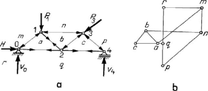
Figure 4.43. A triangular truss (a) and the corresponding Maxwell-Cremona draught (b).
The method of isolation of nodes is graphically concretized in the Maxwell-Cremona
draught. Let be the truss 0-1-2-3-4, acted upon by the forces
1
P and
3
P (Fig.4.43,a).
We use Bow’s notation, denoting by m, n, p, q, r the zones in which is divided the
exterior of the framework by the given and constraint forces which act upon it; as well,
we denote by a, b, c the zones in the interior of the truss, separated by bars or by the
corresponding efforts. Each given and external force and each effort will be expressed
in the form
N
αβ
, where the indices ,αβ correspond to the zones m, n, p, q, r, a, b, c
on one and the other part of the respective force. First of all, the polygon of given and
constraint forces, which is a closed one, is drawn. Then, one constructs the polygon of
forces for the equilibrium of each node, taking the forces clockwise around the node, in
the order in which they are met. We notice that to each node of the truss (Fig.4.43,a)
there corresponds a closed polygon in the Maxwell-Cremona draught (Fig.4.43,b),
while to each closed polygon of the truss (the polygons at the exterior of the truss are
closed at infinity) there corresponds a point of intersection of the respective sides on the
draught. Such figures are called reciprocal, while the method is called the method of
reciprocal polygons too. Denoting the intervals on the framework, the signs of the
efforts are determined on the figure, taking into account the direction along a polygon
according the clockwise direction around the corresponding node on the framework; if
the force stretches the node, then the effort is of tension (as in Fig.4.41), otherwise, it is
of compression.
The compound structures may be studied analogously, by the methods indicated
above. In the case of complex structures in which there is not one node with only two
unknowns and not one section cutting only three non-concurrent members or for which
one cannot make a decomposition in simple structures to which the application of these
methods be possible, one must make – in general – a study of the whole framework;
such a study involves the solution of a system of
2n linear algebraic equations for the
n nodes of the truss. But, from case to case, one can apply the method of bars
replacing of Henneberg or the two sections method of S.A. Tsaplin.
The spatial articulated systems are also systems of bars linked by hinges so as to
form a non-deformable structure from a geometric point of view, and where the loads
are applied at the nodes; but the members of the truss are no more coplanar.
The simple articulated systems are those obtained by joining tetrahedra formed by
bars; such a tetrahedron has six bars, corresponding to its sides. By complete induction,
one can show that