Teodorescu P.P. Mechanical Systems, Classical Models Volume I: Particle Mechanics
Подождите немного. Документ загружается.

MECHANICAL SYSTEMS, CLASSICAL MODELS
170
32 1 5⋅−= degrees of freedom, while for 3n
=
it has 33 3 6
⋅
−= degrees of
freedom. If we suppose that there are still
6 degrees of freedom for n particles, then
for
1n + particles we have 3( 1) 3( 1) 6nn
+
−−= degrees of freedom too (we take
into account that the intervention of a supplementary particle introduces only
3 distinct
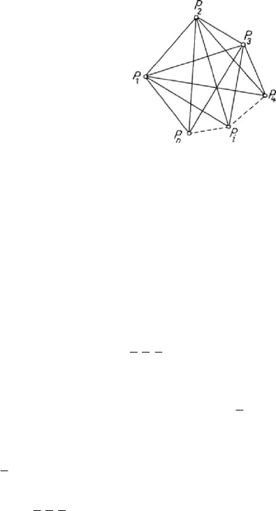
constraints (Fig.3.23)); we have thus proved, by complete induction, that a non-
deformable discrete mechanical system, without external constraints, has
6 degrees of
freedom for
3n ≥ .
Figure 3.23. Degrees of freedom of a non-deformable discrete mechanical system.
This result holds also in the case of a non-deformable continuous mechanical system,
hence in the case of a rigid solid. It is sufficient to show that the position of a rigid solid
is univocally determined with respect to a fixed frame of reference with the aid of six
independent parameters. Let thus be a fixed frame
123
Ox x x
′
′′′
(having a known position
in space) and a movable frame
123
Ox x x , rigidly connected to the rigid solid
(eventually, the pole
O is taken at the centre of mass of the solid); the pole O is
determined by three parameters (the co-ordinates
000
123
,,xxx of its position vector). To
determine the position of the rigid solid with respect to the fixed frame of reference, it
is sufficient to specify the position of the movable frame with respect to the fixed one
or with respect to a frame
123
Ox x x
with the pole at
O
and the axes parallel to the
corresponding axes of the fixed frame (Fig.3.24). We denote by
ON
(the line of nodes)
the intersection of the planes
12
Ox x
′
′
and
12
Ox x
. We give a positive rotation of angle
02ψπ≤< to the axis
1
Ox
′
about the axis
3
Ox
so as to coincide with
ON
and a
positive rotation of angle
02ϕπ
≤
<
to the
ON
-line about the axis
3
Ox
, so as to be
superposed on
1
Ox
; as well, we give a positive rotation of angle
02θπ≤≤
to the
axis
3
Ox
about
ON
so as to coincide with
3
Ox
. The axis
2
Ox
is immediately
obtained, observing that the frame
123
Ox x x
must be a right-handed one. Starting from
the frame
123
Ox x x
, the angles ψ ,
θ
and ϕ , set up in the mentioned order (one
determines firstly the line
ON
, than the axis
3
Ox
and the axis
1
Ox
, and finally the axis
2
Ox
), specify univocally the movable frame, hence they represent three independent
parameters. The angles
ψ ,
θ
and ϕ are called Euler’s angles; the angle ψ is the
precession of the movable frame, the angle
θ
is the nutation of the movable frame,
while the angle
ϕ is the proper rotation of the movable frame, by analogy with the
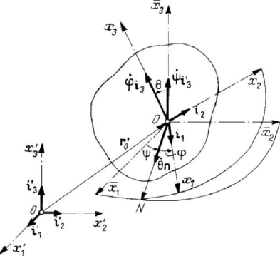
Mass geometry. Displacements. Constraints
171
parameters used in celestial mechanics to determine the position of a planet.
Introducing the column matrices
Figure 3.24. Degrees of freedom of a rigid solid. Euler’s angles ,,ψθϕ.
1
2
3
⎡
⎤
⎢
⎥
=
⎢
⎥
⎢
⎥
⎢
⎥
⎣
⎦
i
ii
i
,
1
2
3
⎡
⎤
′
⎢
⎥
′
′
=
⎢
⎥
⎢
⎥
′
⎢
⎥
⎣
⎦
i
ii
i
(3.2.11)
of the unit vectors of the co-ordinate axes and the matrices
cos sin 0
sin cos 0
001
ψψ
ψψ
⎡⎤
⎢⎥
=−
⎢⎥
⎢⎥
⎢⎥
⎣⎦
Ψ
,
10 0
0cos sin
0sincos
θθ
θθ
⎡
⎤
⎢
⎥
=
⎢
⎥
⎢
⎥
−
⎢
⎥
⎣
⎦
Θ
,
cos sin 0
sin cos 0
001
ϕϕ
ϕϕ
⎡
⎤
⎢
⎥
=−
⎢
⎥
⎢
⎥
⎢
⎥
⎣
⎦
Φ
,
(3.2.11')
which give the direction cosines of the movable frame axes after a rotation of angle
ψ ,
θ or ϕ , respectively, we may write
′
=
ii
Φ
ΘΨ .
(3.2.11'')
The matrix of the direction cosines of the movable frame axes (
j
j
kk
α
′
=
⋅ii) will be of
the form
MECHANICAL SYSTEMS, CLASSICAL MODELS
172
cos cos cos sin sin cos sin cos sin cos sin sin
sin cos cos cos sin sin sin cos cos cos sin cos
sin sin sin cos cos
jk
ϕψ θϕψ ϕψ θϕψ θϕ
α ϕψ θϕψ ϕψ θϕψ θϕ
θψ θψ θ
⎡
⎤
−+
⎢
⎥
=− − − +
⎡⎤
⎢
⎥
⎣⎦
⎢
⎥
−
⎢
⎥
⎣
⎦
,
(3.2.11''')
corresponding to a linear representation of the rotation group
SO(3). Thus, the
position of a rigid solid is univocally determined by six independent parameters (the co-
ordinates
0
1
x ,
0
2
x and
0
3
x of the pole O and Euler’s angles ψ , θ and ϕ ); hence, the
rigid solid has six degrees of freedom.
We can state
Theorem 3.2.1. Any free non-deformable mechanical system (without external
constraints) has six degrees of freedom (excepting the cases of one particle (three
degrees) or of two particles (five degrees)).
2.2.4 Kinematic characterization of constraints
In an inertial frame of reference, the infinitesimal constraints are expressed by
relations between real displacements and the time interval
dt in which these
displacements take place. We may write such a relation in the form
(
)
()
12
d ;d d , d ,...,d ;d 0
n
j
f
tf t
≡
=rrrr,
(3.2.12)
using real displacements, in the case of a discrete mechanical system
S . Developing
into a power series, we have
0
12
... 0
f
fff=+++=
, (3.2.12')
where
k
f
,
0,1,2,...k =
, are homogeneous polynomials of degree k in
()
1
d
j
x ,
()
2
d
j
x ,
()
3
d
j
x ,
1,2,...,jn
=
, and dt (the dimensional homogeneity being ensured). If
0
0
f
≠ , then
k
f
,
1,2,...k =
, can be neglected with respect to
0
f
, so that we get
0
0
f
≡ ; in this case, the constraint is finite. If
0
0
f
≡
but
1
0
f
≠ , then
k
f
,
2, 3,...k =
, can be neglected with respect to
1
f
, and one obtains
1
0
f
=
. (3.2.12'')
If
0
0
f
≡ ,
1
0
f
≡ ,…,
1
0
j
f
−
≡
and 0
j
f
≠
, then we may neglect
k
f
,
1, 2,...kj j=+ + , with respect to
j
f
, so that the relation (3.2.12') becomes 0
j
f
= .
In nature, we do not encounter constraints corresponding to
1j > , so that we will
admit only constraints of the form (3.2.12''). In the case of a discrete mechanical system
S , we express these constraints with the aid of a Pfaff differential form as follows
Mass geometry. Displacements. Constraints
173
0
1
dd0
n
i
ki k
i
tα
=
⋅+ =
∑
rα ,
1,2,...,km
=
,
(3.2.13)
assuming that we have
m constraints; by the above reasoning, the coefficients
ki
α and
0k
α cannot depend on the velocities, so that
(
)
;
j
ki ki
t=ααr ,
(
)
00
;
j
kk
tαα= r ,
being functions of class
1
C . We notice that the relations (3.2.13) can be expressed in
the form
0
1
0
n
i
ki k
i
α
=
⋅+ =
∑
vα , 1,2,...,km
=
,
(3.2.13')
too, by introducing the real velocities
d/d
ii
t
=
vr. We put thus in evidence the
kinematic nature of these constraints; the mechanical system
S cannot have arbitrary
velocities, but only those allowed by the velocity restrictions (3.2.13'). We admit that
the constraints of kinematic nature are distinct, as well as these of geometric nature. In
this case too, we must have
3mn
<
, so that the motion be possible; the difference
3rnm=−
constitutes the number of kinematic degrees of freedom of the mechanical
system
S . This number vanishes if 3mn
=
, and the velocities of the n particles may
be determined (eventually, not univocally), by solving a system of
3n equations with
3n unknowns (the components of the velocities of the n particles). If 3mn> , then
the constraints are no more distinct, what was excluded from the very beginning. As in
the case of finite constraints, the constraints considered above are bilateral ones; the
unilateral constraints of a kinematic nature of the mechanical system
S may be
expressed in the form
0
1
dd0
n
i
ki k
i
tα
=
⋅+ ≥
∑
rα , 1,2,...,km
=
,
(3.2.14)
or in the form
0
1
0
n
i
ki k
i
α
=
⋅+ ≥
∑
vα , 1,2,...,km
=
.
(3.2.14')
If the equality cannot take place for one of the constraints, then that one is called a
strict constraint; but the condition
3mn
<
must still hold.
Passing to the representative space
3n
E , we use the notation (3.2.9), as well as
00kk
bα
=
,
()
i
ki l
kl
α= iα
,
()
,3( 1)
i
ki l
kl
bα
−
+
= ,
1,2,...,in
=
,
1, 2, 3l = , 1,2,...,km
=
.
(3.2.9')
The representative point
P
verifies the conditions
3
0
1
dd0
n
j
kj k
j
bX b t
=
+
=
∑
,
1,2,...,km
=
,
(3.2.13'')
MECHANICAL SYSTEMS, CLASSICAL MODELS
174
or the conditions
3
0
1
0
n
j
kj k
j
bV b
=
+
=
∑
, 1,2,...,km
=
,
(3.2.13''')
where
d
j
X are the generalized real displacements, while d/d
jj
VXt
=
are the
components of the velocity of the point
P
(the generalized velocity) in the
representative space
3n
E
, in the case of bilateral constraints. The unilateral constraints
(3.2.14), (3.2.14') are expressed in the form
3
0
1
dd0
n
j
kj k
j
bX b t
=
+
≥
∑
, 1,2,...,km
=
,
(3.2.14'')
or in the form
3
0
1
0
n
j
kj k
j
bV b
=
+
≥
∑
, 1,2,...,km
=
.
(3.2.14''')
Let
i
′
Δ
r and
i
′′
Δ
r be two possible displacements which take place in the time
interval
tΔ ; the constraint relations may be written in the form
0
1
d0
n
i
ki k
i
tα
=
′
⋅Δ + =
∑
rα ,
0
1
d0
n
i
ki k
i
tα
=
′′
⋅
Δ+ =
∑
rα , 1,2,...,km
=
.
Subtracting and taking into account the relation (3.2.2) which defines the virtual
displacements, we state that the latter ones verify the relations
1
0
n
i
ki
i
=
⋅
δ=
∑
rα
, 1,2,...,km
=
.
(3.2.15)
Comparing with relations (3.2.13), we see once more that the virtual displacements
correspond to a certain moment
t and don’t take place in time. Introducing the virtual
velocities (3.2.1'), one may write these conditions also in the form
1
0
n
i
ki
i
∗
=
⋅
=
∑
vα , 1,2,...,km
=
.
(3.2.15')
If we start from possible displacements which satisfy unilateral constraints
0
1
d0
n
i
ki k
i
tα
=
′
⋅Δ + ≥
∑
rα ,
0
1
d0
n
i
ki k
i
tα
=
′′
⋅
Δ+ ≥
∑
rα ,
1,2,...,km
=
,
we see that the virtual displacements do not satisfy any constraint relation (by
subtraction, one cannot obtain any conclusion concerning the inequalities), being

Mass geometry. Displacements. Constraints
175
reversible. If in the relations concerning the possible displacements
i
′′
Δ
r there is only
the sign “equal” (the constraints are bilateral), then the virtual displacements which are
obtained verify the relations
1
0
n
i
ki
i
=
⋅
δ≥
∑
rα ,
1,2,...,km
=
,
(3.2.16)
corresponding to unilateral constraints; one observes thus that, only in such a case, one
may obtain unilateral constraints for virtual displacements which are irreversible.
Analogously, one can express such constraints also in the form
1
0
n
i
ki
i
∗
=
⋅
≥
∑
vα , 1,2,...,km
=
.
(3.2.16')
If
j
Xδ are generalized virtual displacements (obtained as differences of generalized
possible displacements
j
X
′
Δ and
j
X
′
′
Δ
), we may write, for the representative point
P
in the space
3n
E , the constraint relations in the form (bilateral constraints)
3
1
0
n
j
kj
j
bX
=
δ=
∑
, 1,2,...,km
=
,
(3.2.15'')
or in the form
3
1
0
n
j
kj
j
bV
∗
=
=
∑
, 1,2,...,km
=
,
(3.2.15''')
where
j
V
∗
are generalized virtual velocities (which can be introduced as differences of
generalized possible velocities
j
V
′
and
j
V
′
′
); in the case of unilateral constraints
(obtained as we have seen above), we use the relations
3
1
0
n
j
kj
j
bX
=
δ≥
∑
,
1,2,...,km
=
,
(3.2.16'')
or the relations
3
1
0
n
j
kj
j
bV
∗
=
≥
∑
, 1,2,...,km
=
.
(3.2.16''')
2.2.5 Case of a particle subjected to finite constraints
Let be the case of a single particle
P
, of position vector r and co-ordinates
123
,,xxx, subjected to finite constraints
()
(
)
123
;,,;0
kk
f
tfxxxt≡=r , 1, 2k
=
;
(3.2.17)
MECHANICAL SYSTEMS, CLASSICAL MODELS
176
hence, the particle can be on a surface (we have only
1k
=
) or on a curve (at the
intersection of two surfaces). A total differentiation with respect to time leads to
conditions imposed to the velocity of the particle, in the form
,
d
grad 0
d
k
j
kkkjk
f
fffvf
t
=⋅+=+=
v , 1, 2k
=
;
(3.2.18)
it results
2
grad
grad
k
kk
k
f
f
f
=
−+
vc, grad
kk
f
⊥
c ,
1, 2k
=
.
(3.2.18')
The component of the velocity along the gradient (along the normal to the
corresponding surface) is given by
grad
k
k
g
k
f
v
f
=−
, 1, 2k
=
,
(3.2.18'')
while its component in a plane normal to the gradient is arbitrary; one obtains thus two
components of the velocity. The total derivative of the relation (3.2.18) with respect to
time leads to conditions imposed to the acceleration of the particle, given by
2
2
2
d
grad D 0
d
k
kk
f
ff
t
=⋅+=a , 1, 2k
=
,
(3.2.19)
where we have introduced the notation
2
,,
D
jj
kkjllkj k
f
fvv fv f
=
++
;
(3.2.19')
we obtain thus the acceleration
2
2
D
grad
grad
k
kk
k
f
f
f
=
−+ac, grad
kk
f
⊥
c , 1, 2k
=
.
(3.2.19'')
Analogously, the component of the acceleration along the gradient is
2
D
grad
k
k
g
k
f
a
f
=− , 1, 2k
=
,
(3.2.19''')
while its component in a plane normal to the gradient is arbitrary; we obtain thus two
components of the acceleration.
In the case of a unilateral constraint
(;) 0
k
f
t ≥r , 1, 2k
=
,
(3.2.20)

Mass geometry. Displacements. Constraints
177
the velocity and the acceleration are not subjected, in general, to any condition. If at a
moment
t the constraint is bilateral ( () 0
k
f
t
=
), and than it becomes strict
(
()0
k
f
tt+Δ > , 0tΔ> ), then we can use a development into a Taylor series
2
2
2
dd
11
( ) ( ) ) ...
1! d 2!
d
kk
kk
f
f
ft t ft t t
t
t
+Δ = + Δ + (Δ +
;
in the frame of this hypothesis, we obtain, for
0t
Δ
→ , the conditions d/d 0
k
f
t ≥ ,
which may be expressed also in the form
grad 0
kk
f
f
⋅
+≥
v
,
1, 2k
=
.
(3.2.20')
If the constraint is strict, then it acts only on the velocity by which the particle leaves
the surface
0
k
f
= , and not on the velocity by which it reaches the surface (because we
have admitted that
0tΔ> ); the acceleration of the particle remains arbitrary. If we
have
d/d 0
k
f
t = at a moment t , then – by an analogous reasoning – we obtain the
constraints
2
2
2
d
grad D 0
d
k
kk
f
ff
t
=⋅+≥a
, 1, 2k
=
.
(3.2.20'')
2.2.6 Holonomic and non-holonomic constraints
If the Pfaff differential form (3.2.13) is integrable, hence if the first member of the
relation (3.2.13'') is a total differential with respect to the variables
j
X and t , then the
constraints have been denominated holonomic by Hertz; otherwise, they are called non-
holonomic. We see that the holonomic constraints expressed in the form (3.2.13) are not
infinitesimal, but finite ones, and may be represented in the form (3.2.8); thus, a
holonomic mechanical system is a system with finite constraints or with infinitesimal
integrable constraints (which – in fact – are finite constraints).
The finite holonomic constraints (3.2.8) may be expressed also by means of
infinitesimal displacements in the form (relations of the form (3.2.13)).
11
dgraddd dd0
nn
ii ii
lllll
ii
ffftfft
==
= ⋅+=∇⋅+=
∑∑
rr,
(3.2.21)
wherefrom
()
l
ij
li l
i
j
f
f
x
∂
=∇ =
∂
iα , 1,2,...,in
=
,
0ll
f
α
=
, 1,2,...,lp
=
.
(3.2.21')
The virtual displacements must verify the relations
1
0
n
ii
l
i
f
=
∇⋅δ=
∑
r
, 1,2,...,lp
=
.
(3.2.21'')

MECHANICAL SYSTEMS, CLASSICAL MODELS
178
Let be two neighbouring, possible, simultaneous (at the moment
t ) positions
i
r and
ii
+δrr,
1,2,...,in=
, of the same holonomic discrete mechanical system. The
constraint relations are of the form
() 0
j
l
f
=
r , ()0
jj
l
f
+
δ=rr ,
1,2,...,lp=
.
Developing into a Taylor series, we may write
()
1
... 0
n
jii
ll
i
ff
=
+
∇⋅δ+=
∑
rr;
neglecting the terms of higher order and taking into account the constraint relations, one
obtains the conditions (3.2.21''). One can see once more that
i
δ
r
represent the
differential displacements which must be effected by the particles of the mechanical
system to pass from a position to another one, at the same moment
t
, being thus virtual
displacements, corresponding to the relation of definition (3.2.2).
The relations (3.2.21) lead to the conditions
1
0
n
ii
ll
i
ff
=
∇⋅ +=
∑
v ,
1,2,...,lp
=
,
(3.2.21''')
which must be verified by the velocities of the particles of the system; obviously, in
these relations only the components of the velocities along the corresponding gradients
of the constraints are involved. For instance, let be the particles
i
P and
j
P at an
invariable mutual distance (or two points of a rigid solid); the relation (see Fig.1.18)
()
2
2
const
ji ij
r−==rr
(3.2.22)
takes place. Differentiating with respect to time (or applying the formula (3.2.21''')), we
get
ij i ij j
⋅
=⋅rv rv; (3.2.22')
hence, the projections of the velocities of two points of a non-deformable mechanical
system along the straight line defined by them are equal.
In what concerns the conditions imposed to the accelerations, we obtain
2
2
2
1
d
D0
d
n
l
ii
ll
i
f
ff
t
=
=∇⋅+ =
∑
a , 1,2,...,lp
=
,
(3.2.23)
where
2
,,
11 1
D
nn n
ij i
llijlil
ij i
f
fvv fv f
== =
=++
∑∑ ∑
, 1,2,...,lp
=
.
(3.2.23')
Thus, in the case of the non-deformable two points system considered above, we may
write

Mass geometry. Displacements. Constraints
179
()( )
2
0
ij j i j i
⋅−+− =raa vv .
(3.2.23'')
We notice that, in the case of holonomic constraints, the number of degrees of
freedom
s given by the finite displacements is equal to the number of degrees of
freedom
r given by the infinitesimal displacements (sr
=
).
The non-holonomic constraints are expressed by relations of the form (3.2.13'),
which represent conditions which must be verified by the real velocities. The total
derivative with respect to time puts into evidence the conditions which are to be
verified by the accelerations of the non-holonomic discrete mechanical system, i.e.,
0
11
dd
0
dd
nn
ki k
ii
ki
ii
tt
α
==
⋅+ ⋅+ =
∑∑
av
α
α
, 1,2,...,km
=
;
(3.2.24)
as in the case of the velocities, only the components of the accelerations along the
parameters
ki
α
are involved in this case too.
One can make analogous considerations in the representative space
3n
E . Let be
3
0
1
dd
n
j
kkj k
j
bX b tω
=
=+
∑
, 1,2,...,km
=
, 3mn
<
,
(3.2.25)
a differential form of the first degree, corresponding to the constraint relations
(3.2.13''); these relations lead to a differential equation of the form
0
k
ω = . The form
k
ωω= (for a fixed k ) is (locally) integrable if there exist two functions 0
f
≠ and g
so that
d
f
gω
=
; the problem is thus reduced to the existence of an integrating factor
for the considered differential equation. One may prove that the functions
f
and g do
exist (in a sufficiently small neighbourhood) if and only if there exists a form of the
first degree
θ , so that
dωθω=∧, d0ωω
∧
= , (3.2.26)
where we used the external product defined in the App., Subsec. 1.2.1. We introduce
the matrices
1
2
m
ω
ω
ω
⎡⎤
⎢⎥
⎢⎥
=
⎢⎥
⎢⎥
⎢⎥
⎣⎦
#
Ω ,
11 12 1
21 22 2
12
m
m
mm
mm
f
ff
ff f
ff f
⎡
⎤
⎢
⎥
⎢
⎥
=
⎢
⎥
⋅
⋅⋅
⎢
⎥
⎢
⎥
⎣
⎦
"
"
"
"
F
,
1
2
m
g
g
g
⎡
⎤
⎢
⎥
⎢
⎥
=
⎢
⎥
⎢
⎥
⎢
⎥
⎣
⎦
#
G
,
11 12 1
21 22 2
12
m
m
mm
mm
θθ θ
θθ θ
θθ θ
⎡
⎤
⎢
⎥
⎢
⎥
=
⎢
⎥
⋅
⋅⋅
⎢
⎥
⎢
⎥
⎣
⎦
"
"
"
"
Θ
,
(3.2.27)