Pumping Station Desing - Second Edition by Robert L. Sanks, George Tchobahoglous, Garr M. Jones
Подождите немного. Документ загружается.

D
is the
throat diameter
of the
intake
(in
either meters
or
feet),
so for a
throat
of
1.0
m
(3.28 ft),
for
example,
the
discharge
is
limited
to 6.2
m
3
/s
(220
ft
3
/s).
There
are two
designs
of the FSL The one
with
the
lowest
profile
(and hence
the
unit
of
least cost)
is
shown
in
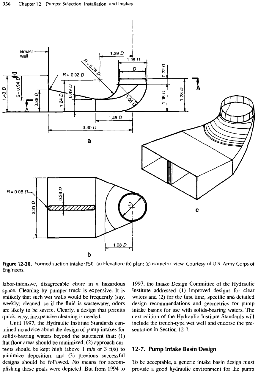
Figure 12-30 (page 356). Flow
may
approach
the
intake
at any
angle
up to
90°.
In
studies
of
a
model with
a
throat diameter
of 200 mm (8
in.),
forebay
velocities
of
1.2
m/s
(4
ft/s),
or
even twice
as
much,
caused
no
problems, according
to
Fletcher
[15],
and
velocities
in the
throat
met all
requirements
for
uniformity
and
lack
of
swirling
or
vortices. Corre-
sponding prototype
velocities
can be
found using
the
model similitude relationships presented
in
Section
3-
12.
Caution with respect
to
high forebay velocities
is,
however,
advised.
Not
every design with
FSI
intakes
works
equally well, however,
and the
configuration
of
the
forebay does
affect
swirling
and
vortices,
as
dem-
onstrated
in
model tests
by
Fletcher
[16].
The
dividing
wall
in the
entrance
is not a
problem, because trash
racks
are
assumed
to be
placed
in the
forebay
to
elim-
inate debris. Without trash racks, expect stringy mate-
rial
to be
deposited
on the
nose
of the
dividing wall.
A
schematic drawing
of a
wastewater pumping sta-
tion
wet
well containing pumps
originally
designed
to
discharge
a
total
flow of
6300
m
3
/h
(40
Mgal/d)
is
shown
in
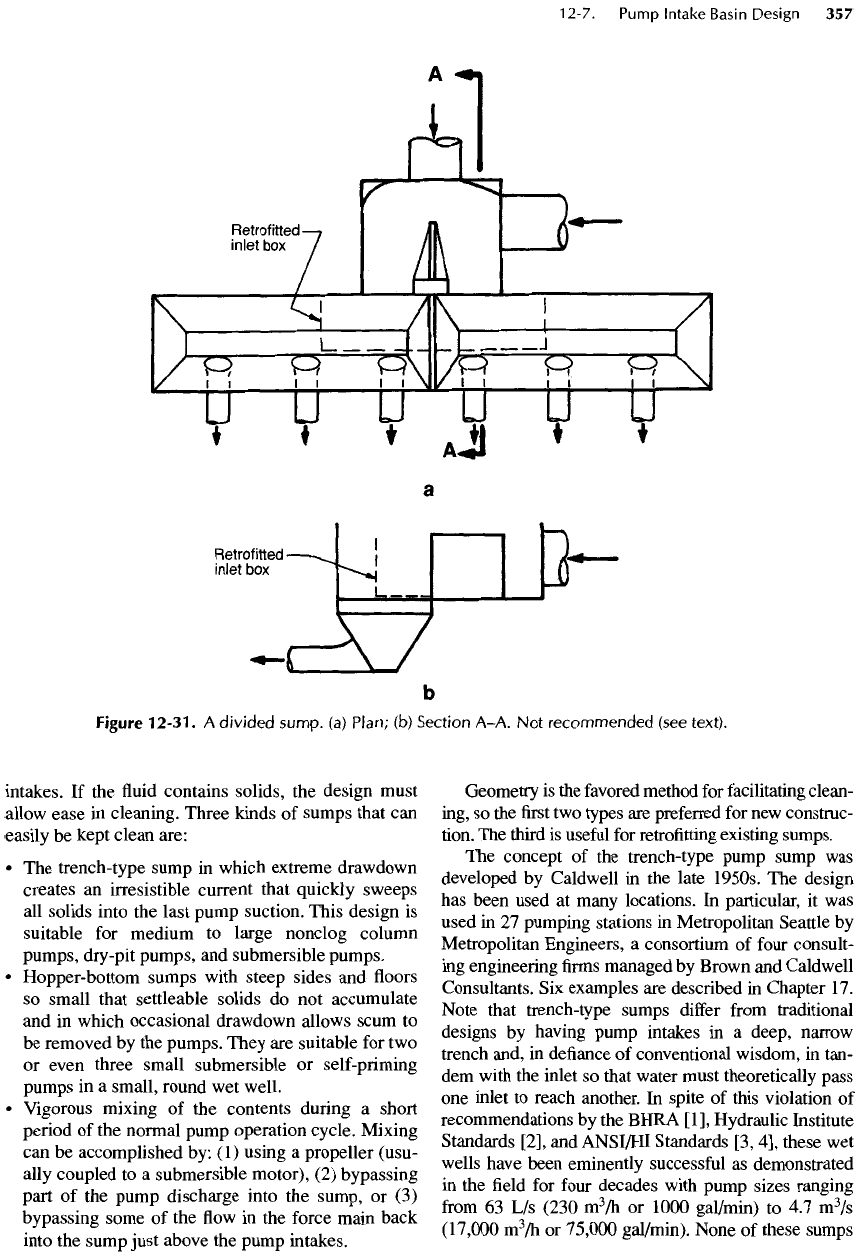
Figure 12-31 (page 357).
The
pumps were
very
noisy
and
impeller noses were quickly eroded,
so
impellers
had to be
replaced
frequently. When nearly
double
the
capacity
was
required,
a
model study
was
made.
The
model proved that even
a
very short cas-
cade (less than
0.3 m or 1 ft in the
prototype) into
the
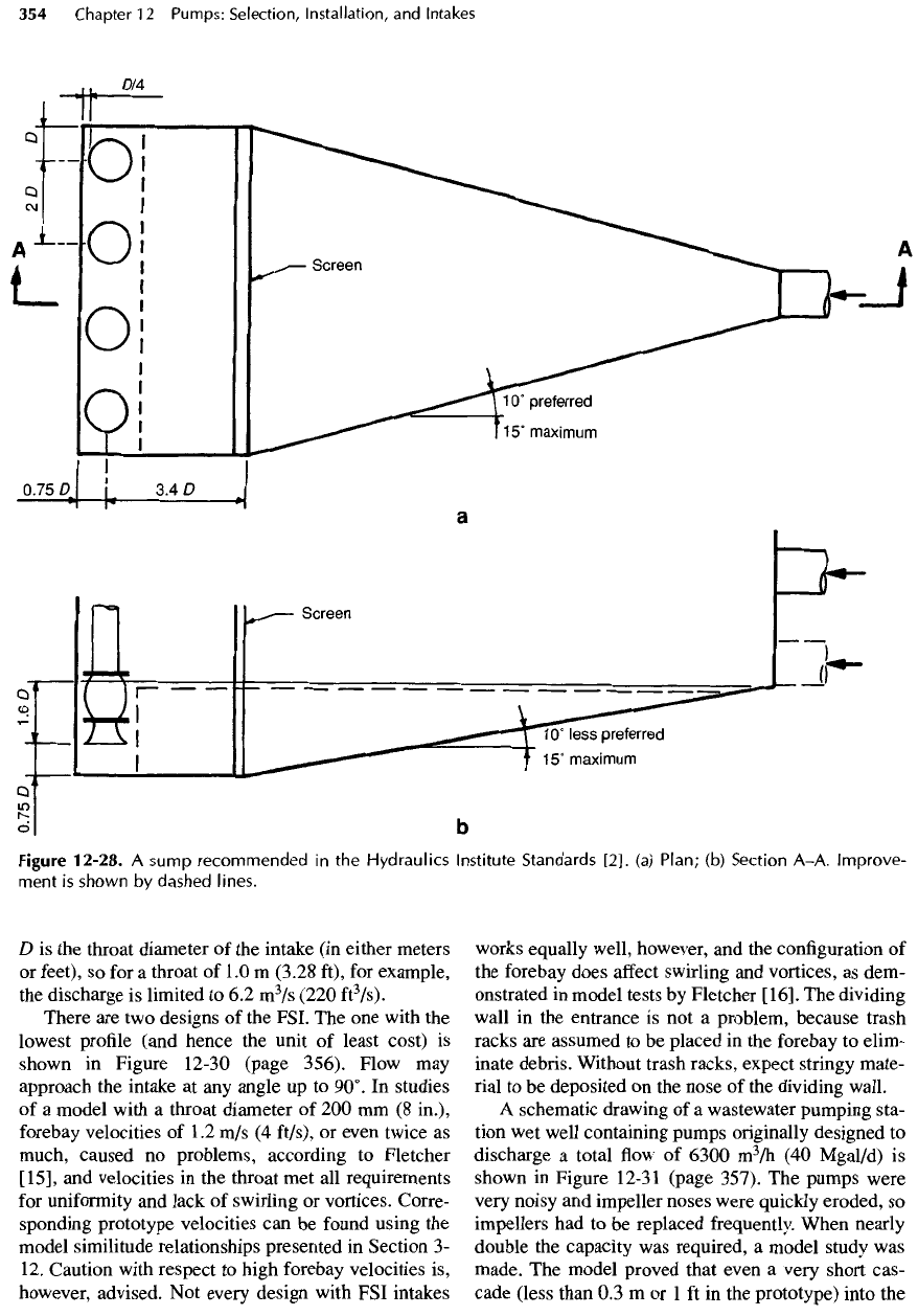
Figure
12-28.
A
sump recommended
in the
Hydraulics Institute Standards
[2].
(a)
Plan;
(b)
Section A-A. Improve-
ment
is
shown
by
dashed lines.
wet
well caused great masses
of air
bubbles
to be
driven
to the floor
where
the
pump intake currents
captured them, thereby creating noise
and
erosion.
The
poor characteristics were overcome
by
installing
the
baffle
channel, shown
by the
dashed lines
in the
figure.
Water
from
the
cascade
falls
into
the
channel
and
must enter
the
sump horizontally. Hence,
the
bub-
bles
are not
driven
to the floor of the
sump
and
thus
can float to the
surface.
No
bubbles entered
any
pump
intake
after
the
baffle
was
installed even
at the
high
discharge
of
4700
m
3
/h
(30
Mgal/d)
per
pump,
and the
pumps
ran
smoothly even
at a
station discharge
of
7500
m
3
/h
(118
Mgal/d).
The wet
well still traps
sludge
and
scum, however,
and
remains unsatisfactory
for
that reason.
Air
bubbles entrained
by a
free
fall
can
persist
for a
surprisingly long time
and are
readily drawn into
pump intakes with devastating
effects
on
capacity,
head,
and
efficiency.
One % of air
can,
for
example,
reduce
the
efficiency
and
throughput
of
some pumps
by
as
much
as
15%.
Pumps with
a low
specific speed
(n
s
)
are
more sensitive
to air
than those with
a
high
specific
speed. With
a
sufficient
residence time
in the
sump
and
enough distance between
the
inlet
to the
sump
and the
pump intake,
the air
bubbles
can be
eliminated. Information given
by
Falvey [17]
is
useful
for
estimating this distance.
Solids-Bearing
Waters
Many
waters (raw water,
stormwater,
and
wastewater)
contain solids that settle rapidly
in
traditional
wet
well
designs
as the
velocity
at the
exit
of the
inlet pipe
falls
to
very
low
values
in the
sump.
As a
result,
all of the
above
designs
are
generally unsuitable
for
such
waters.
The
deposition
of
solids
can
change
the
hydraulic characteristics
of the
basin appreciably, and,
if
any
organic material
is
present,
its
decomposition
results
in
toxic, malodorous,
and
corrosive gases.
Usually such solids
can be
removed
from
these sumps
only
with
difficulty
and at
considerable
expense.
Designs
for
solids-bearing waters
are
specifically
avoided
in the
Hydraulic Institute Standards
[2]
with
the
statement "Figures
apply
to
sumps
for
clear liq-
uids.
For
fluid-
solids
mixtures
refer
to the
pump man-
ufacturer"
In a
later
edition [3],
the
wording
is
"This
standard
applies
to
handling clear
liquids"
and
these
warnings preclude,
for
example,
the use of
such
sumps
as
illustrated
in
Figures 12-26
to
12-29
for
solids-bearing waters. When,
despite
the
warning, tra-
ditional designs
are
used
for
water containing solids,
sludge accumulates,
often
quickly. Sometimes sumps
are
divided
(as in
Figure
12-31)
to
allow
one
side
to
remain
in
service while
the
other
is
isolated
and
man-
ually
cleaned.
But the
manual
cleaning
of
sumps
is a
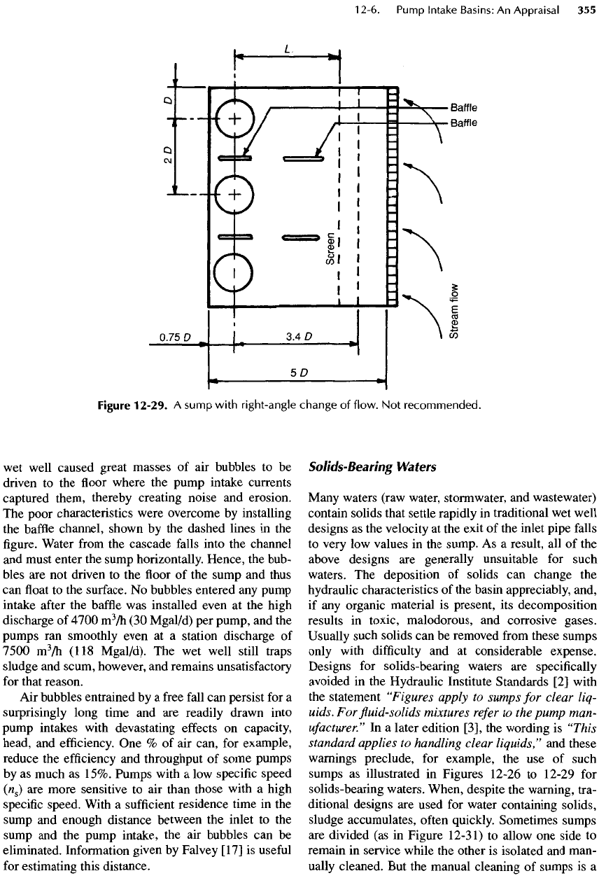
Figure
12-29.
A
sump
with
right-angle
change
of
flow.
Not
recommended.
labor-intensive,
disagreeable
chore
in a
hazardous
space. Cleaning
by
pumper truck
is
expensive.
It is
unlikely
that
such
wet
wells would
be
frequently
(say,
weekly)
cleaned,
so if the fluid is
wastewater, odors
are
likely
to be
severe. Clearly,
a
design that permits
quick,
easy, inexpensive cleaning
is
needed.
Until
1997,
the
Hydraulic Institute Standards con-
tained
no
advice about
the
design
of
pump intakes
for
solids-bearing waters beyond
the
statement that:
(1)
flat floor
areas should
be
minimized,
(2)
approach cur-
rents
should
be
kept high (above
1 m/s or 3
ft/s)
to
minimize
deposition,
and (3)
previous successful
designs should
be
followed.
No
means
for
accom-
plishing
these goals were depicted.
But
from
1994
to
1997,
the
Intake
Design
Committee
of the
Hydraulic
Institute addressed
(1)
improved designs
for
clear
waters
and (2) for the first
time,
specific
and
detailed
design recommendations
and
geometries
for
pump
intake basins
for use
with solids-bearing waters.
The
next
edition
of the
Hydraulic Institute Standards will
include
the
trench-type
wet
well
and
endorse
the
pre-
sentation
in
Section
12-7.
12-7.
Pump
Intake
Basin
Design
To
be
acceptable,
a
generic
intake basin design must
provide
a
good hydraulic environment
for the
pump
Figure
12-30.
Formed
suction
intake
(FSI).
(a)
Elevation;
(b)
plan;
(c)
isometric
view.
Courtesy
of
U.S.
Army
Corps
of
Engineers.
intakes.
If the fluid
contains solids,
the
design must
allow
ease
in
cleaning. Three kinds
of
sumps that
can
easily
be
kept clean are:
• The
trench-type sump
in
which extreme drawdown
creates
an
irresistible current that quickly sweeps
all
solids into
the
last pump suction.
This
design
is
suitable
for
medium
to
large nonclog column
pumps,
dry
-pit
pumps,
and
submersible
pumps.
•
Hopper-bottom sumps with steep sides
and
floors
so
small that settleable solids
do not
accumulate
and
in
which
occasional
drawdown allows scum
to
be
removed
by the
pumps. They
are
suitable
for two
or
even three small submersible
or
self-priming
pumps
in a
small, round
wet
well.
•
Vigorous mixing
of the
contents
during
a
short
period
of the
normal pump operation cycle. Mixing
can
be
accomplished
by:
(1)
using
a
propeller (usu-
ally
coupled
to a
submersible motor),
(2)
bypassing
part
of the
pump discharge into
the
sump,
or (3)
bypassing some
of the flow in the
force main back
into
the
sump just above
the
pump intakes.
Geometry
is the
favored
method
for
facilitating clean-
ing,
so the first two
types
are
preferred
for new
construc-
tion.
The
third
is
useful
for
retrofitting
existing sumps.
The
concept
of the
trench-type pump sump
was
developed
by
Caldwell
in the
late
1950s.
The
design
has
been used
at
many locations.
In
particular,
it was
used
in 27
pumping stations
in
Metropolitan Seattle
by
Metropolitan Engineers,
a
consortium
of
four
consult-
ing
engineering
firms
managed
by
Brown
and
Caldwell
Consultants.
Six
examples
are
described
in
Chapter
17.
Note that trench-type sumps
differ
from
traditional
designs
by
having pump intakes
in a
deep,
narrow
trench and,
in
defiance
of
conventional wisdom,
in
tan-
dem
with
the
inlet
so
that water must theoretically pass
one
inlet
to
reach another.
In
spite
of
this violation
of
recommendations
by the
BHRA
[1],
Hydraulic Institute
Standards [2],
and
ANSI/HI
Standards
[3, 4],
these
wet
wells have been eminently
successful
as
demonstrated
in the field for
four
decades
with pump
sizes
ranging
from
63 L/s
(230
m
3
/h
or
1000
gal/min)
to 4.7
m
3
/s
(17,000
m
3
/h
or
75,000
gal/min). None
of
these sumps
Figure
12-31.
A
divided
sump,
(a)
Plan;
(b)
Section
A-A.
Not
recommended
(see
text).
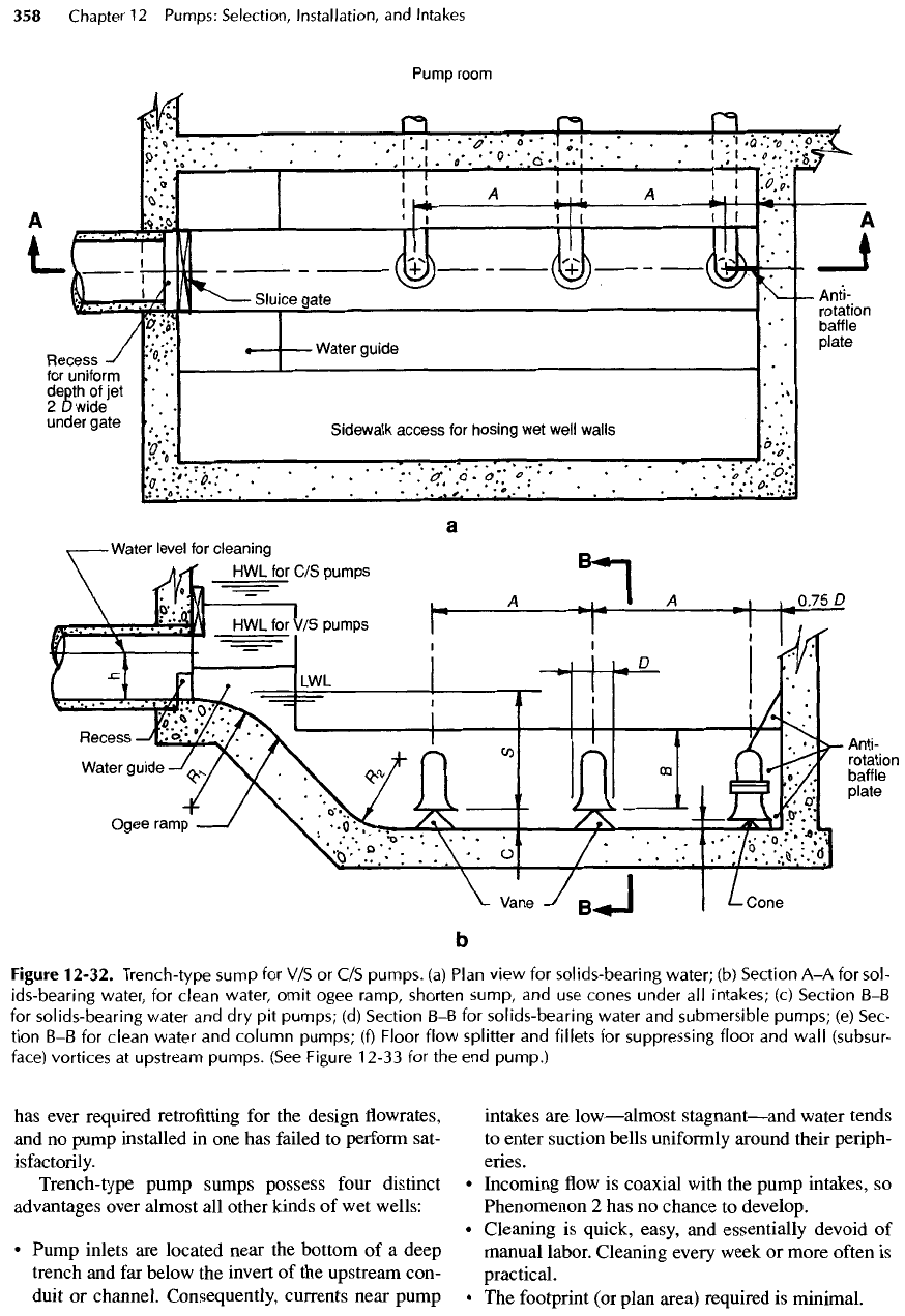
has
ever required retrofitting
for the
design
flowrates,
and
no
pump installed
in one has
failed
to
perform sat-
isfactorily.
Trench-type
pump sumps possess
four
distinct
advantages
over almost
all
other kinds
of wet
wells:
•
Pump inlets
are
located near
the
bottom
of a
deep
trench
and far
below
the
invert
of the
upstream con-
duit
or
channel. Consequently, currents near pump
intakes
are
low
—
almost
stagnant
—
and
water tends
to
enter suction bells uniformly around their periph-
eries.
•
Incoming
flow is
coaxial with
the
pump intakes,
so
Phenomenon
2 has no
chance
to
develop.
•
Cleaning
is
quick, easy,
and
essentially devoid
of
manual
labor. Cleaning every week
or
more
often
is
practical.
• The
footprint
(or
plan area) required
is
minimal.
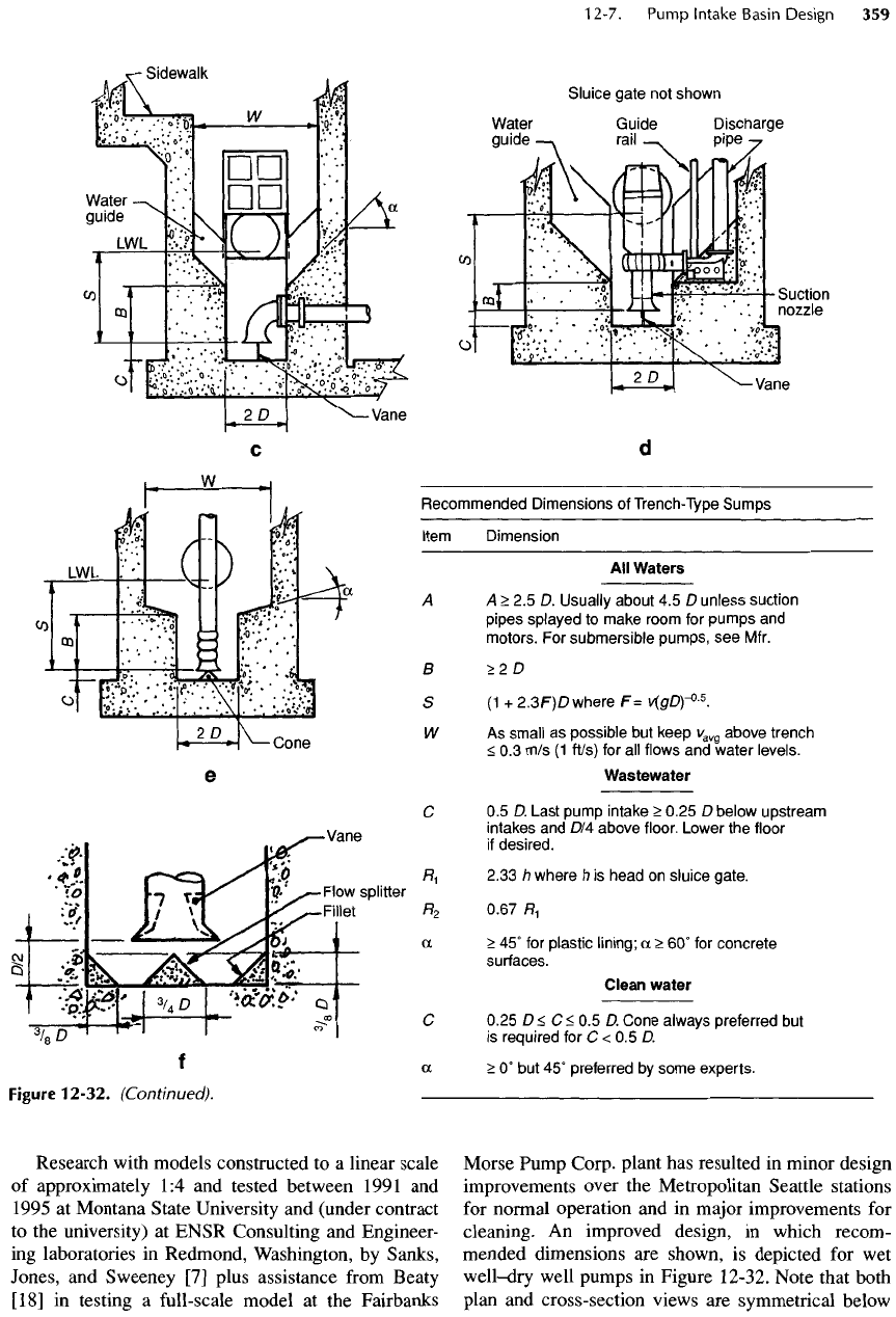
Figure
12-32.
Trench-type sump
for V/S or C/S
pumps,
(a)
Plan
view
for
solids-bearing
water;
(b)
Section
A-A
for
sol-
ids-bearing
water,
for
clean
water,
omit
ogee
ramp,
shorten
sump,
and use
cones
under
all
intakes;
(c)
Section
B-B
for
solids-bearing water
and dry pit
pumps;
(d)
Section
B-B for
solids-bearing water
and
submersible
pumps;
(e)
Sec-
tion
B-B for
clean water
and
column
pumps;
(f)
Floor
flow
splitter
and
fillets
for
suppressing
floor
and
wall
(subsur-
face)
vortices
at
upstream pumps. (See Figure
12-33
for the end
pump.)
Research with models constructed
to a
linear scale
of
approximately
1:4
and
tested between 1991
and
1995
at
Montana State University
and
(under contract
to the
university)
at
ENSR Consulting
and
Engineer-
ing
laboratories
in
Redmond, Washington,
by
Sanks,
Jones,
and
Sweeney
[7]
plus assistance
from
Beaty
[18]
in
testing
a
full-scale model
at the
Fairbanks
Morse Pump Corp. plant
has
resulted
in
minor design
improvements over
the
Metropolitan Seattle stations
for
normal operation
and in
major improvements
for
cleaning.
An
improved
design,
in
which
recom-
mended
dimensions
are
shown,
is
depicted
for wet
well-dry
well pumps
in
Figure 12-32. Note that both
plan
and
cross-section views
are
symmetrical below
Figure
12-32.
(Continued).
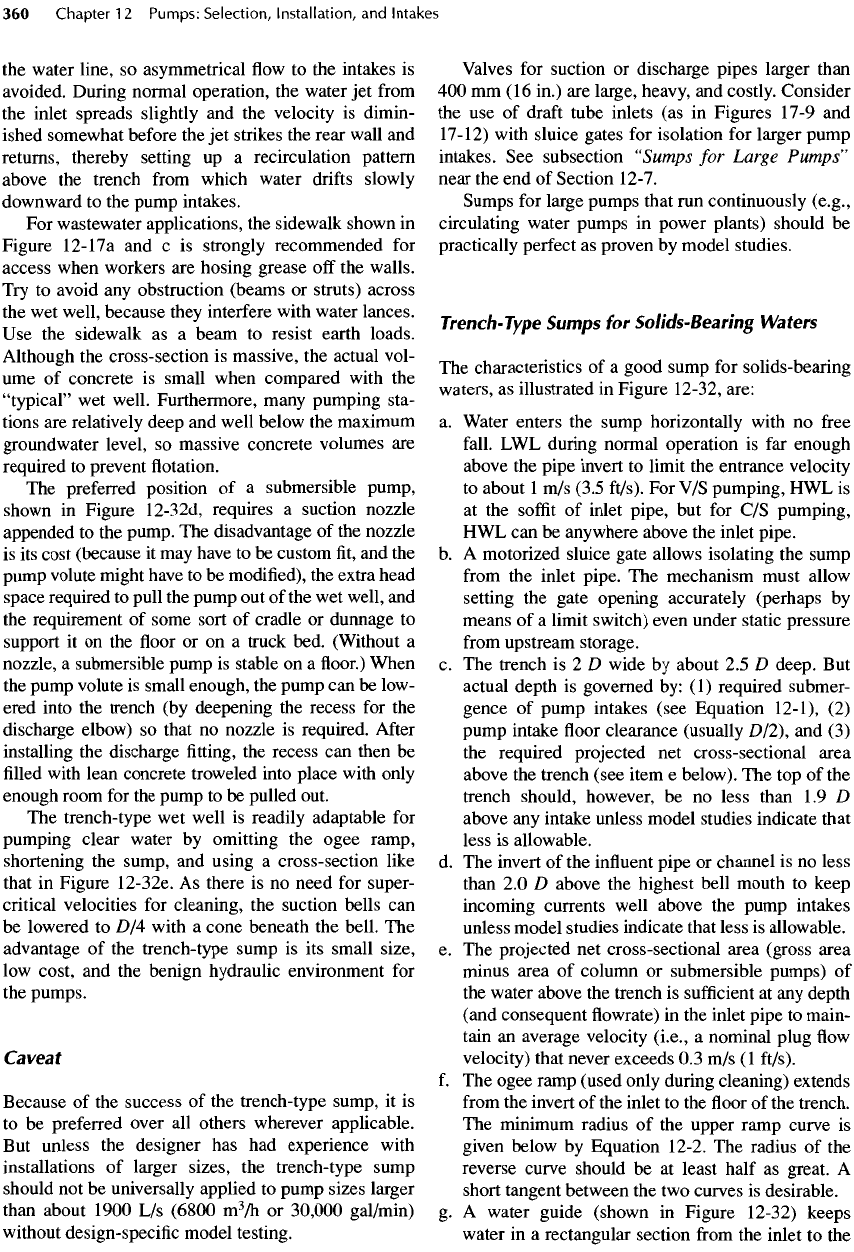
Recommended
Dimensions
of
Trench-Type
Sumps
Item
Dimension
All
Waters
A
A
>
2.5 D.
Usually about
4.5 D
unless suction
pipes
splayed
to
make room
for
pumps
and
motors.
For
submersible pumps,
see
Mfr.
a
>2D
S (1 +
2.3F)D
where
F=
v[gD)-°-
5
.
W
As
small
as
possible
but
keep
v
avQ
above trench
<
0.3
m/s
(1
ft/s)
for all
flows
and
water levels.
Wastewater
C 0.5 D.
Last pump intake
>
0.25
D
below upstream
intakes
and
D/4
above
floor.
Lower
the
floor
if
desired.
H
1
2.33
/?
where
h
is
head
on
sluice gate.
R
2
0.67
H
1
a
>
45° for
plastic lining;
a
>
60° for
concrete
surfaces.
Clean water
C
0.25
D
<
C
<
0.5 D.
Cone always preferred
but
is
required
for C < 0.5 D.
oc
>
0° but 45°
preferred
by
some experts.
the
water line,
so
asymmetrical
flow to the
intakes
is
avoided. During normal operation,
the
water
jet
from
the
inlet spreads slightly
and the
velocity
is
dimin-
ished somewhat before
the jet
strikes
the
rear wall
and
returns,
thereby setting
up a
recirculation
pattern
above
the
trench
from
which water
drifts
slowly
downward
to the
pump intakes.
For
wastewater applications,
the
sidewalk shown
in
Figure
12-11
a
and c is
strongly recommended
for
access when workers
are
hosing grease
off the
walls.
Try
to
avoid
any
obstruction (beams
or
struts) across
the wet
well, because they interfere with water lances.
Use the
sidewalk
as a
beam
to
resist earth loads.
Although
the
cross-section
is
massive,
the
actual vol-
ume
of
concrete
is
small when compared with
the
"typical"
wet
well. Furthermore, many pumping sta-
tions
are
relatively deep
and
well below
the
maximum
groundwater
level,
so
massive concrete volumes
are
required
to
prevent
flotation.
The
preferred position
of a
submersible pump,
shown
in
Figure 12-32d, requires
a
suction nozzle
appended
to the
pump.
The
disadvantage
of the
nozzle
is
its
cost (because
it may
have
to be
custom
fit, and the
pump
volute might have
to be
modified),
the
extra head
space required
to
pull
the
pump
out of the wet
well,
and
the
requirement
of
some sort
of
cradle
or
dunnage
to
support
it on the floor or on a
truck bed. (Without
a
nozzle,
a
submersible pump
is
stable
on a floor.)
When
the
pump volute
is
small enough,
the
pump
can be
low-
ered into
the
trench
(by
deepening
the
recess
for the
discharge elbow)
so
that
no
nozzle
is
required.
After
installing
the
discharge
fitting, the
recess
can
then
be
filled
with
lean concrete troweled into place with only
enough
room
for the
pump
to be
pulled out.
The
trench-type
wet
well
is
readily adaptable
for
pumping
clear water
by
omitting
the
ogee
ramp,
shortening
the
sump,
and
using
a
cross-section like
that
in
Figure 12-32e.
As
there
is no
need
for
super-
critical velocities
for
cleaning,
the
suction bells
can
be
lowered
to
D
/4
with
a
cone beneath
the
bell.
The
advantage
of the
trench-type sump
is its
small size,
low
cost,
and the
benign hydraulic environment
for
the
pumps.
Caveat
Because
of the
success
of the
trench-type sump,
it is
to
be
preferred over
all
others wherever applicable.
But
unless
the
designer
has had
experience with
installations
of
larger sizes,
the
trench-type sump
should
not be
universally applied
to
pump sizes larger
than
about 1900
L/s
(6800
m
3
/h
or
30,000
gal/min)
without
design-specific model testing.
Valves
for
suction
or
discharge pipes larger than
400 mm
(16
in.)
are
large, heavy,
and
costly. Consider
the use of
draft
tube inlets
(as in
Figures 17-9
and
17-12) with sluice gates
for
isolation
for
larger pump
intakes.
See
subsection
"Sumps
for
Large
Pumps"
near
the end of
Section
12-7.
Sumps
for
large pumps that
run
continuously (e.g.,
circulating water pumps
in
power plants) should
be
practically perfect
as
proven
by
model studies.
Trench-Type
Sumps
for
Solids-Bearing
Waters
The
characteristics
of a
good sump
for
solids-bearing
waters,
as
illustrated
in
Figure
12-32, are:
a.
Water enters
the
sump horizontally with
no
free
fall.
LWL
during normal operation
is far
enough
above
the
pipe invert
to
limit
the
entrance velocity
to
about
1 m/s
(3.5
ft/s).
For V/S
pumping,
HWL is
at
the
soffit
of
inlet pipe,
but for C/S
pumping,
HWL can be
anywhere above
the
inlet
pipe,
b.
A
motorized sluice gate allows isolating
the
sump
from
the
inlet pipe.
The
mechanism must allow
setting
the
gate opening accurately (perhaps
by
means
of a
limit switch) even under static pressure
from
upstream
storage,
c. The
trench
is 2 D
wide
by
about
2.5 D
deep.
But
actual
depth
is
governed
by: (1)
required submer-
gence
of
pump intakes (see Equation 12-1),
(2)
pump
intake
floor
clearance (usually
D/2),
and (3)
the
required projected
net
cross-sectional area
above
the
trench (see item
e
below).
The top of the
trench should, however,
be no
less than
1.9 D
above
any
intake unless model studies indicate that
less
is
allowable,
d. The
invert
of the
influent
pipe
or
channel
is no
less
than
2.0 D
above
the
highest bell mouth
to
keep
incoming currents well above
the
pump intakes
unless model studies indicate that less
is
allowable,
e. The
projected
net
cross-sectional area (gross area
minus
area
of
column
or
submersible pumps)
of
the
water above
the
trench
is
sufficient
at any
depth
(and
consequent
flowrate) in the
inlet
pipe
to
main-
tain
an
average velocity (i.e.,
a
nominal plug
flow
velocity) that never exceeds
0.3 m/s (1
ft/s).
f
.
The
ogee ramp (used only during cleaning) extends
from
the
invert
of the
inlet
to the floor of the
trench.
The
minimum radius
of the
upper ramp curve
is
given below
by
Equation 12-2.
The
radius
of the
reverse curve should
be at
least half
as
great.
A
short tangent between
the two
curves
is
desirable.
g.
A
water guide (shown
in
Figure 12-32) keeps
water
in a
rectangular section
from
the
inlet
to the
trench. Without
the
guide, water climbs
up the
sloping sides,
falls
back into
the
trench,
and
inter-
feres
with
the flow of
water along
the
trench during
cleaning,
h.
Above
the
trench,
the
sides
are
sloped
at
least
45°
if
lined with,
for
example,
PVC (or
another plastic
equally slick)
or 60° if the
surface
is
smooth con-
crete (steeper
is
better)
to
assist solids
to
slide into
the
trench.
PVC
makes
it
easier
to
hose grease
and
debris
off the
walls.
For
wastewater,
the
entire
sump
above
LWL
should
be
lined with
a
plastic
such
as
Linabond®
[19]
to
prevent
corrosion,
i.
Intakes
may be
spaced
as
close
as 2.5 D
center
to
center. Closer spacing
may be
used subject
to
model
study.
For
intakes
so
close, splay
the
pump
suction
pipes apart
so
that pumps
and
valves have
a
clear space
on
three sides
of no
less than
l.lm
(42
in.),
j.
Upstream intakes
are no
less than
D
12
above
the
floor to
avoid interference with
the
supercritical
flow
of
water during cleaning. Interference pat-
terns generated
at the
sides
of the
trench during
cleaning
may
cause shock waves
(or
"rooster
tails")
that
can
reach
a
height
of
D/2.
Their
impingement
on a
suction bell
can
interfere with
the flow of
water
underneath,
k. For flat floors as in
Figures 12-32c
to
12-32e,
the
entrance velocity
at the
mouth
of the
pump suction
bell (based
on the OD of the
bell)
should
be
1
.
1
m/s
(3.5 ft/s)
or
less
for V/S
pumping
and 0.9 m/s
(3.0 ft/s)
or
less
for C/S
pumping.
To
ensure
effec-
tive disposal
of the
largest grit particles during
cleaning, however,
the
entrance velocity
at
full
dis-
charge capacity should
not be
less than about
0.6 m/
s
(2.0
ft/s).
Velocity
in the
suction pipe should
not
exceed
2.5 m/s (8
ft/s).
If
these restrictions
are
incompatible
with standard
bells,
the
bells
can be
machined
to a
smaller size.
1.
The
last pump intake clears
the end
wall
by,
prefer-
ably,
no
more than
D
/4
to
inhibit
surface
vortices.
The
intake must
be no
more than
D/4
above
the
upstream
trench
floor. The
intake
can be
lowered
by
sloping
the floor
downward
from
the
adjacent
intake
to a
lower elevation
and
retaining
a floor
clearance
of
D/4.
The
lowered suction intake cre-
ates
a
more vigorous
jump,
m. An
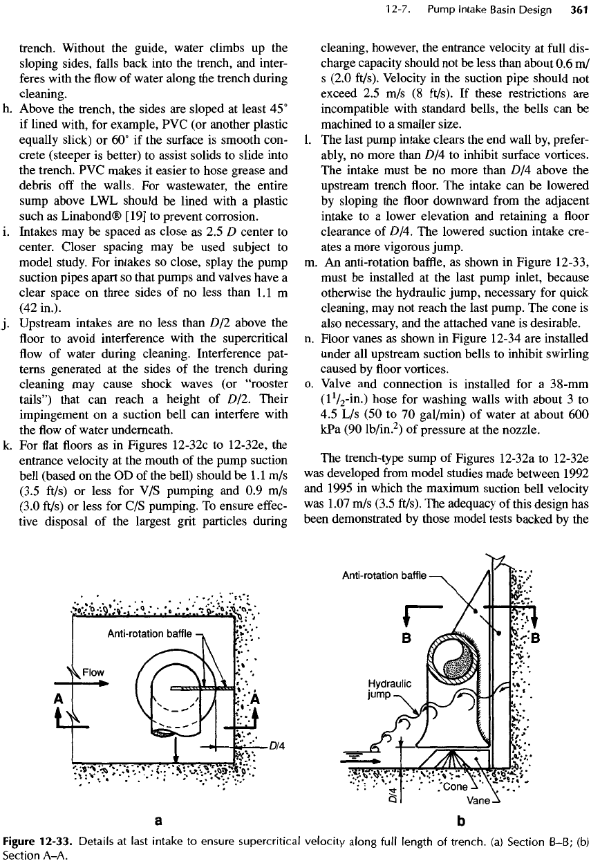
anti-rotation
baffle,
as
shown
in
Figure
12-33,
must
be
installed
at the
last pump inlet, because
otherwise
the
hydraulic jump, necessary
for
quick
cleaning,
may not
reach
the
last pump.
The
cone
is
also necessary,
and the
attached vane
is
desirable,
n.
Floor
vanes
as
shown
in
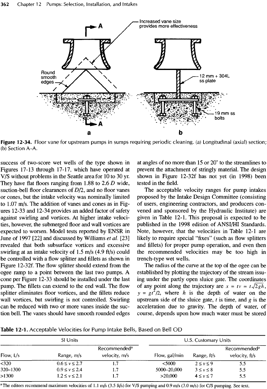
Figure 12-34
are
installed
under
all
upstream suction bells
to
inhibit swirling
caused
by floor
vortices,
o.
Valve
and
connection
is
installed
for a 3
8
-mm
(l
l
/
2
-in.)
hose
for
washing walls with about
3 to
4.5 L/s (50 to 70
gal/min)
of
water
at
about
600
kPa
(90
lb/in.
2
)
of
pressure
at the
nozzle.
The
trench-type sump
of
Figures 12-32a
to
12-32e
was
developed
from
model studies made between 1992
and
1995
in
which
the
maximum suction
bell
velocity
was
1.07
m/s
(3.5
ft/s).
The
adequacy
of
this design
has
been demonstrated
by
those model tests backed
by the
Figure
12-33.
Details
at
last
intake
to
ensure supercritical
velocity
along
full
length
of
trench,
(a)
Section B-B;
(b)
Section A-A.
success
of
two-score
wet
wells
of the
type shown
in
Figures
17-13
through
17-17,
which have operated
at
V/S
without problems
in the
Seattle area
for 10 to 30 yr.
They have
flat floors
ranging
from
1.88
to 2.6 D
wide,
suction-bell
floor
clearances
of
D/2,
and no floor
vanes
or
cones,
but the
intake velocity
was
nominally limited
to
1
.07
m/s.
The
addition
of
vanes
and
cones
as in
Fig-
ures
12-33
and
12-34
provides
an
added factor
of
safety
against swirling
and
vortices.
At
higher intake veloci-
ties, however,
the
submerged
floor and
wall vortices
are
expected
to
worsen. Model tests reported
by
ENSR
in
June
of
1997 [22]
and
discussed
by
Williams
et
al
[23]
revealed that both
subsurface
vortices
and
excessive
swirling
at an
intake velocity
of
1.5
m/s
(4.9 ft/s) could
be
controlled
with
a flow
splitter
and fillets as
shown
in
Figure 12-32f.
The flow
splitter should extend
from
the
ogee ramp
to a
point between
the
last
two
pumps.
A
cone
per
Figure 12-33 should
be
installed under
the
last
pump.
The fillets can
extend
to the end
wall.
The flow
splitter eliminates
floor
vortices,
and the fillets
reduce
wall
vortices,
but
swirling
is not
controlled. Swirling
can
be
reduced with
two or
more vanes inside
the
suc-
tion
bell.
The
vanes should have smooth rounded edges
at
angles
of no
more than
15 or 20° to the
streamlines
to
prevent
the
attachment
of
stringly
material.
The
design
shown
in
Figure 12-32f
has not yet (in
1998) been
tested
in the field.
The
acceptable velocity ranges
for
pump intakes
proposed
by the
Intake Design Committee (consisting
of
users, engineering contractors,
and
producers con-
vened
and
sponsored
by the
Hydraulic Institute)
are
given
in
Table
12-1.
This proposal
is
expected
to be
published
in the
1998 edition
of
ANSI/HI
Standards.
Note, however, that
the
velocities
in
Table
12-1
are
likely
to
require special "fixes" (such
as flow
splitters
and
fillets) for
proper pump operation,
and
even then
the
recommended velocities
may be too
high
in
trench-type
wet
wells.
The
radius
of the
curve
at the top of the
ogee
can be
established
by
plotting
the
trajectory
of the
stream issu-
ing
under
the
partly open sluice gate.
The
coordinates
of
any
point along
the
trajectory
are x = tv =
t+j2gh,
y
= gt /2,
where
h is the
depth
of
water
on the
upstream side
of the
sluice gate,
t is
time,
and g is the
acceleration
due to
gravity.
The
depth
of
water,
of
course, depends upon
how
much water must
be
stored
Table
12-1.
Acceptable
Velocities
for
Pump
Intake
Bells,
Based
on
Bell
OD
Sl
Units U.S. Customary Units
Recommended
3
Recommended
3
Flow,
L/s
Range,
m/s
velocity,
m/s
Flow,
gal/min
Range,
ft/s
velocity,
ft/s
<320
0.6
<
v
<
2.7LT
<5000
2<v<9
53
320-1300
0.9<v<2.4
1.7
5000-20,000
3<v<8
5.5
>1300
1.2<v<2.1
1.7
>20,000
4<v<7
5.5
a
The
editors recommend
maximum
velocities
of
1.1
m/s
(3.5 ft/s)
for V/S
pumping
and 0.9 m/s
(3.0 m/s)
for C/S
pumping.
See
text.
Figure
12-34.
Floor
vane
for
upstream
pumps
in
sumps
requiring
periodic
cleaning,
(a)
Longitudinal
(axial)
section;
(b)
Section A-A.
to
complete
the
cleaning cycle (see Example 12-5).
The
trajectory
is a
parabola,
and a
circular curve
fits it
only
approximately.
For
practical purposes, however,
the
radius,
R,
of a
circular curve with
its
center
on a
point
directly below
the
sluice gate
is,
with
no
factor
of
safety:
R
=
2.33
h
(12-2)
where
R is the
radius
and h is
defined
above.
The
upper
curve
should
end in a
short tangent
no
steeper than
45°
before
beginning
the
reverse curve. There seems
to be
no
rational basis
for
determining
a
satisfactory radius
for
the
reverse curve.
In
early tests
at
Fairbanks Morse
Pump
Corp. (described above),
a
short radius produced
a
high shock wave, which
was
substantially reduced
by
a
radius approximately equal
to
that
of the
upper curve.
Note
that items
g and h
above combine
to
establish
the
cross-section geometry, dimensions,
and the
water
levels.
The
number
of
pumps
and
their spacing (see item
i
above) establish
the
length and, hence,
the
volume
of
the
sump.
For V/S
pumping,
the
volume
is
irrelevant,
because
outflow
always equals
inflow.
For C/S
pump-
ing,
the
volume
of the
sump plus
the
volume stored
in
upstream
piping must
be
sufficient
to
limit
the
frequency
of
motor starts
and the
resting periods
to
safe
values.
Controls
for V/S
Pumping
One
advantage
of V/S
pumping (aside
from
the
small
size
of the
sump required)
is
that
the
influent
sewer
pipe
can be
used
as
part
of the
sump
by
keeping
the
water
surface
in the
sump
at the
same elevation
as the
normal
depth
within
the
sewer pipe.
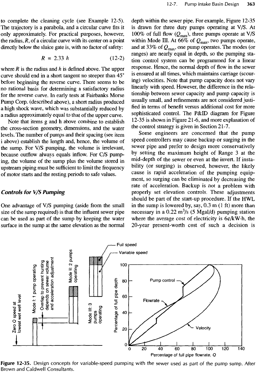
For
example, Figure 12-35
is
drawn
for
three duty pumps operating
at
V/S.
At
100%
of
full
flow
(C
max
),
three pumps operate
at V/S
within
Mode III.
At 66% of
Q
max
,
two
pumps operate,
and
at
33%
of
<2
max
,
one
P
um
P
operates.
The
modes
(or
ranges)
are
nearly equal
in
depth,
so the
pumping sta-
tion control system
can be
programmed
for a
linear
response. Hence,
the
normal depth
of flow in the
sewer
is
ensured
at all
times, which maintains carriage (scour-
ing) velocities. Note that pump capacity does
not
vary
linearly with
speed.
However,
the
difference
in the
rela-
tionship between sewer capacity
and
pump capacity
is
usually
small,
and
refinements
are not
considered justi-
fied
in
terms
of
benefit
versus additional cost
for
more
sophisticated control.
The
P&ID
diagram
for
Figure
12-35
is
shown
in
Figure
21-6,
and
more explanation
of
the
control strategy
is
given
in
Section
21-7.
Some engineers
are
concerned that
the
pump
speed
controllers
may
cause backup
or
surging
in the
sewer
pipe
and
prefer
to
design more conservatively
by
setting
the
maximum height
of
Range
3 at the
mid-depth
of the
sewer
or
even
at the
invert.
If
insta-
bility
(or
surging)
is
observed, however,
the
likely
cause
is
rapid acceleration
of the
pumping equip-
ment,
so
surging
can be
eliminated
by
decreasing
the
rate
of
acceleration. Backup
is not a
problem with
properly
set
elevation controls. These adjustments
should
be
part
of the
start-up procedure.
If the HWL
in
the
sump
is
lowered
by,
say,
0.3 m (1 ft)
more than
necessary
in a
0.22
m
3
/s
(5
Mgal/d)
pumping station
where
the
average cost
of
electricity
is
60/kW-h,
the
20-year present-worth cost
of
such
a
decision
is
Figure
12-35.
Design
concepts
for
variable-speed
pumping
with
the
sewer used
as
part
of the
pump
sump.
After
Brown
and
Caldwell
Consultants.
