Pumping Station Desing - Second Edition by Robert L. Sanks, George Tchobahoglous, Garr M. Jones
Подождите немного. Документ загружается.

nearly
$5000.
The
free
fall
also induces turbulence,
odor
release,
and air
entrainment
in the
sump, with
the
potential
for
damage
to the
pumping equipment.
Cleaning
Trench-Type
Sumps
The
purpose
of
frequently cleaning pump sumps
is to
prevent
odors,
to
protect
the
facilities (especially
elec-
tronic
and
electrical gear)
from
corrosion caused
by
hydrogen
sulfide
in the air
within
the
station,
to
eject
scum
before
it can
form
hard
rafts,
and to
prevent
banks
of
sludge
from
interfering with
flow
patterns.
To
eject scum,
the
scum must
be
concentrated into
the
smallest possible area close (both horizontally
and
vertically)
to a
pump intake
so
that
it can be
quickly
and
easily sucked
by a
strong vortex into
the
pump
intake during
the
cleaning
process.
Sludge
and
grit
must
be
swept along
the
trench
by a
strong current
to a
pump
intake
in
which
the
velocity
is
high enough
to to
lift
sand
and
small gravel particles into
the
pump.
An
approximate
relationship
between
the
current
and the
movement
of
sand beds
is
shown
in
Figure
12-36.
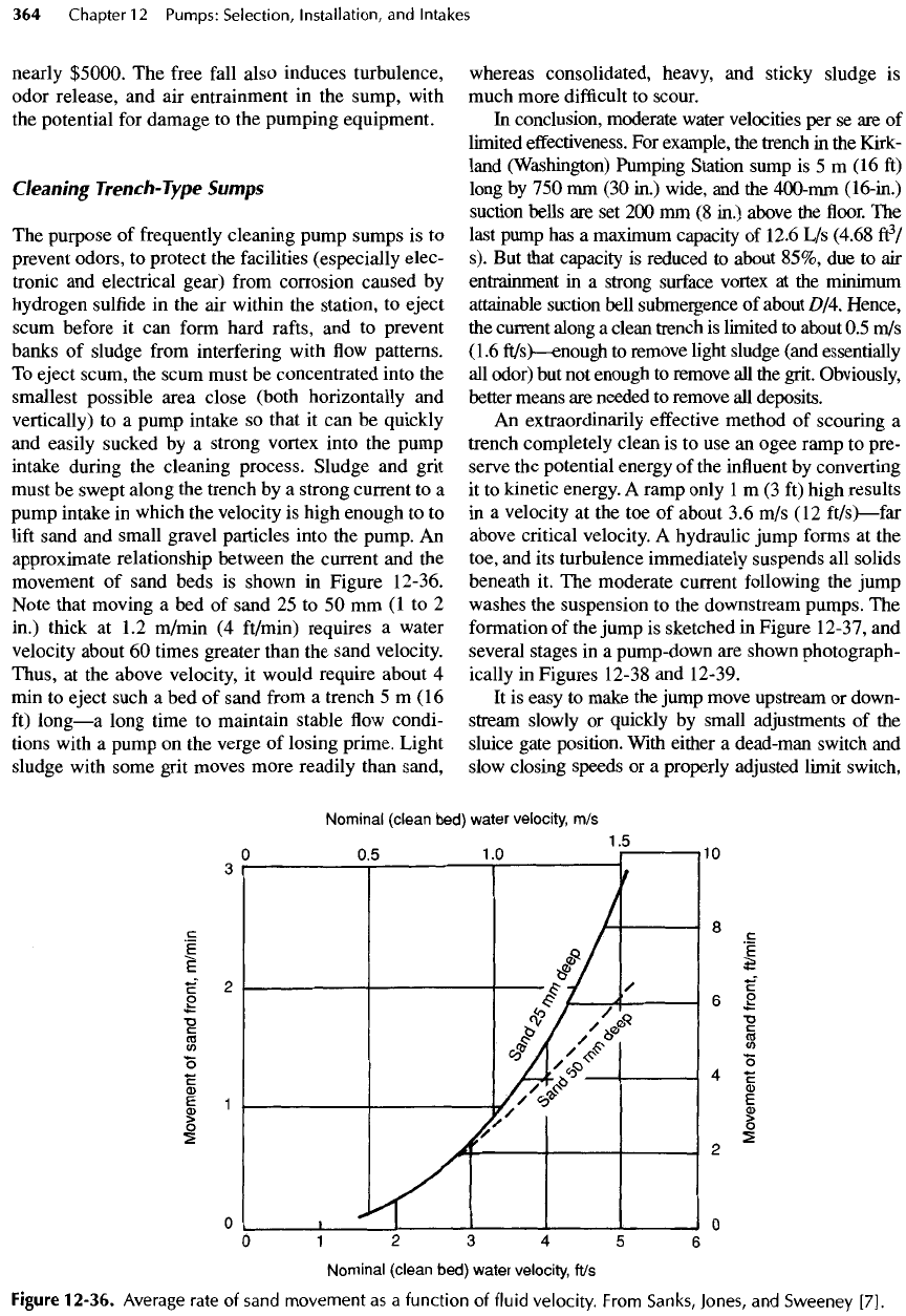
Note that moving
a bed of
sand
25 to 50 mm (1 to 2
in.)
thick
at 1.2
m/min
(4
ft/min)
requires
a
water
velocity
about
60
times greater than
the
sand velocity.
Thus,
at the
above velocity,
it
would
require
about
4
min
to
eject such
a bed of
sand
from
a
trench
5 m (16
ft)
long
—
a
long time
to
maintain stable
flow
condi-
tions with
a
pump
on the
verge
of
losing prime. Light
sludge with some grit moves more readily than sand,
whereas consolidated, heavy,
and
sticky sludge
is
much more
difficult
to
scour.
In
conclusion, moderate water velocities
per se are of
limited
effectiveness.
For
example,
the
trench
in the
Kirk-
land
(Washington) Pumping Station sump
is 5 m (16 ft)
long
by 750 mm (30
in.)
wide,
and the
400-mm
(16-in.)
suction bells
are set 200 mm (8
in.)
above
the floor. The
last
pump
has a
maximum capacity
of
12.6
L/s
(4.68
ft
3
/
s). But
that capacity
is
reduced
to
about 85%,
due to air
entrainment
in a
strong
surface
vortex
at the
minimum
attainable suction
bell
submergence
of
about D/4. Hence,
the
current along
a
clean trench
is
limited
to
about
0.5
m/s
(1.6
ft/s)
—
enough
to
remove light sludge (and essentially
all
odor)
but not
enough
to
remove
all the
grit. Obviously,
better means
are
needed
to
remove
all
deposits.
An
extraordinarily
effective
method
of
scouring
a
trench completely clean
is to use an
ogee ramp
to
pre-
serve
the
potential energy
of the
influent
by
converting
it
to
kinetic energy.
A
ramp only
1 m (3 ft)
high results
in
a
velocity
at the toe of
about
3.6 m/s (12
ft/s)
—
far
above critical velocity.
A
hydraulic jump forms
at the
toe,
and its
turbulence immediately suspends
all
solids
beneath
it. The
moderate current following
the
jump
washes
the
suspension
to the
downstream pumps.
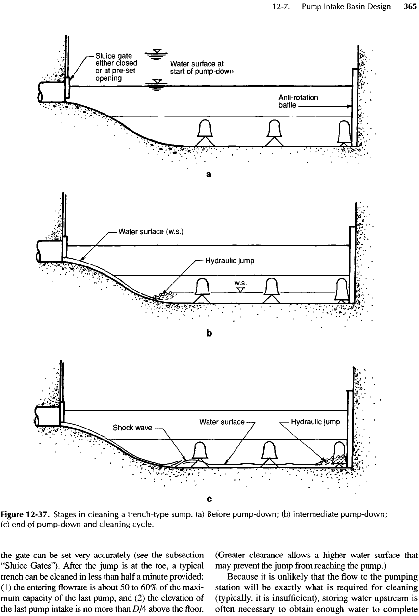
The
formation
of the
jump
is
sketched
in
Figure
12-37,
and
several stages
in a
pump-down
are
shown photograph-
ically
in
Figures
12-38
and
12-39.
It is
easy
to
make
the
jump move upstream
or
down-
stream
slowly
or
quickly
by
small adjustments
of the
sluice gate position. With either
a
dead-man switch
and
slow
closing speeds
or a
properly
adjusted
limit switch,
Figure
12-36.
Average
rate
of
sand
movement
as a
function
of
fluid velocity.
From
Sanks,
Jones,
and
Sweeney
[7].
the
gate
can be set
very accurately (see
the
subsection
"Sluice
Gates").
After
the
jump
is at the
toe,
a
typical
trench
can be
cleaned
in
less than half
a
minute provided:
(1)
the
entering
flowrate is
about
50 to 60% of the
maxi-
mum
capacity
of the
last pump,
and (2) the
elevation
of
the
last pump intake
is no
more than
D/4
above
the floor.
(Greater clearance allows
a
higher water
surface
that
may
prevent
the
jump
from
reaching
the
pump.)
Because
it is
unlikely that
the flow to the
pumping
station will
be
exactly what
is
required
for
cleaning
(typically,
it is
insufficient),
storing water upstream
is
often
necessary
to
obtain enough water
to
complete
Figure
12-37.
Stages
in
cleaning
a
trench-type
sump,
(a)
Before
pump-down;
(b)
intermediate
pump-down;
(c)
end of
pump-down
and
cleaning
cycle.
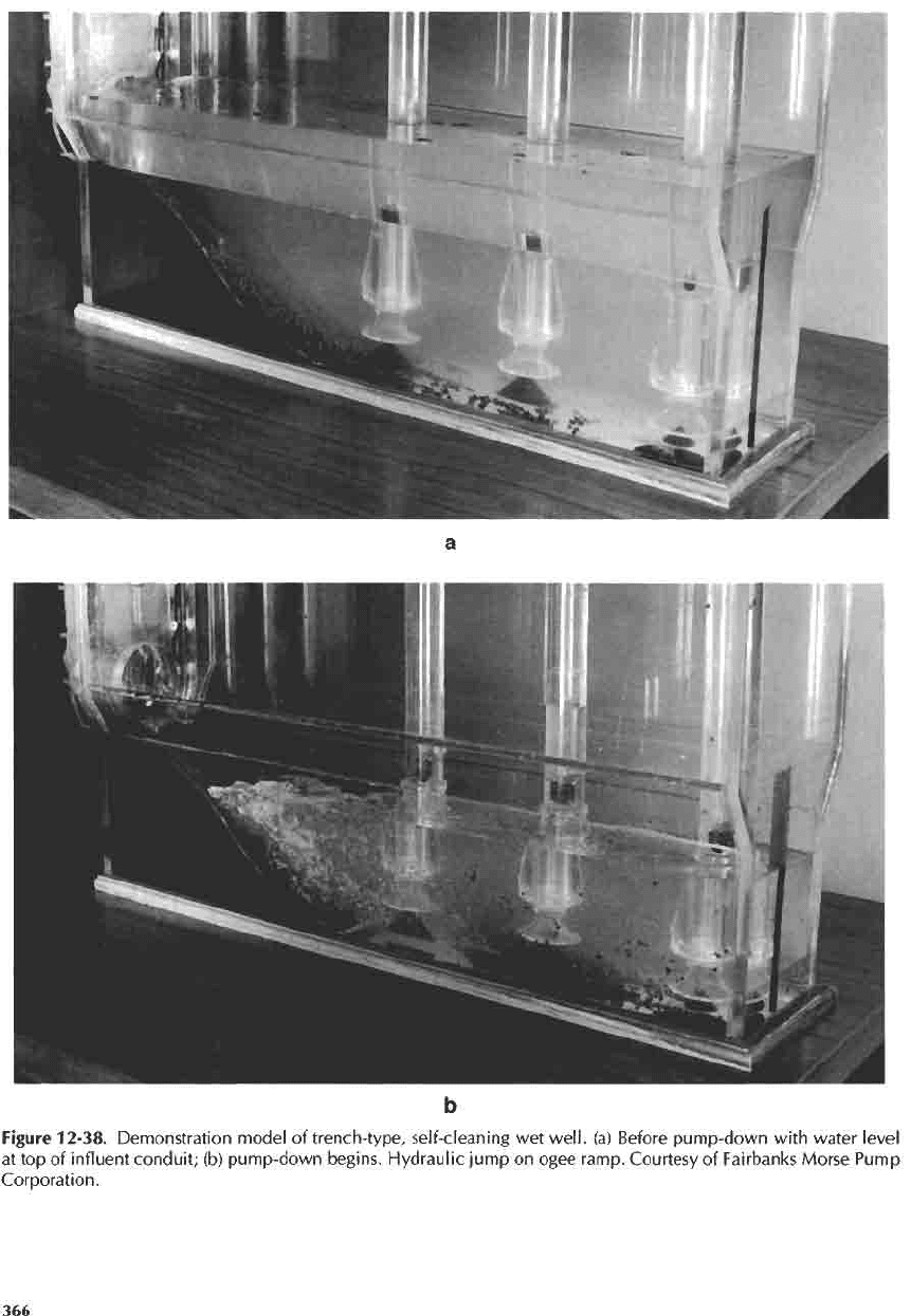
Figure
12-38. Demonstration model
of
trench-type,
self-cleaning
wet
well,
(a)
Before
pump-down
with
water level
at
top of
influent conduit;
(b)
pump-down begins. Hydraulic jump
on
ogee ramp. Courtesy
of
Fairbanks
Morse Pump
Corporation.
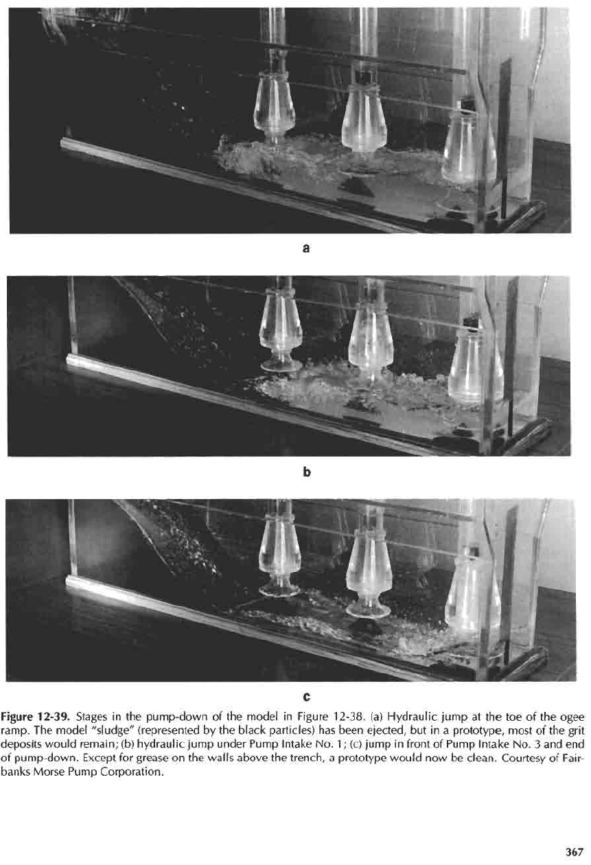
Figure
12-39.
Stages
in the
pump-down
of the
model
in
Figure
12-38.
(a)
Hydraulic
jump
at the toe of the
ogee
ramp.
The
model "sludge" (represented
by the
black particles)
has
been
ejected,
but in a
prototype,
most
of the
grit
deposits
would
remain;
(b)
hydraulic jump under Pump Intake
No.
1;
(c)
jump
in
front
of
Pump Intake
No. 3 and end
of
pump-down.
Except
for
grease
on the
walls above
the
trench,
a
prototype
would
now be
clean. Courtesy
of
Fair-
banks
Morse Pump Corporation.
the
cleaning
cycle.
There
are two
ways
to
store
the
water
and to
operate
the
pumps
and
sluice gate.
The
first
way
is to:
•
Close
the
sluice gate
to
store water
in the
upstream
piping.
•
When enough water
is
stored upstream, dewater
the
wet
well with
the
last pump.
•
Open
the
sluice gate
to
deliver somewhat less
flow
than
the
last pump
can
discharge
—
easy
to do
with
V/S
pumps. With
C/S
pumps, this operation
requires close timing
and
might
be
unsuccessful.
•
Hose grease
off
the
walls while
the
sump
is
dewatered.
• The
trench
is now
clean.
Open
the
sluice gate
and
restore
the
station
to
normal automatic operation.
Reprime
the
pumps
as
necessary.
The
second
way is to:
•
Lower
the
sluice gate until
it
reaches
its
proper, pre-
determined position.
•
Simultaneously
shut
off
all the
pumps
to
allow
the
water
level
behind
the
sluice gate
to
rise
to
such
a
level
that
sufficient
water
is
stored
to
complete
the
cleaning cycle.
•
Turn
on all the
pumps (even
the
standby pump,
if
the
facilities
can
withstand such
a
discharge without
damage)
at
full
speed
to
dewater
the
sump
as
rap-
idly
as
possible. Upstream pumps remove some
of
the
sludge until they lose prime. Being
set at a
lower elevation,
the
last pump
is the
last
to
lose
prime,
and it
does
so
only when
the
jump
reaches
it.
Use the
dead-man switch
to
jockey
the
gate
so
that
the
jump travels down
the
trench
at the
desired rate.
•
Turn
off the
upstream pumps
as
they lose prime.
A
limit switch
on the
check valve lever
or
(better)
a
power monitor
in the MCC is
advantageous
for
doing
so
automatically. Continue
to
operate
the
last
pump
for a few
seconds
after
the
jump reaches
it.
•
Hose grease
off
the
walls while
the
sump
is
dewatered.
• The
trench
is now
clean. Open
the
sluice
gate
and
restore
the
station
to
normal automatic operation.
Reprime
the
pumps
as
necessary.
Sluice
Gates
The
sluice
gate,
its
operating mechanism,
and its
installation
are
vital
in
ensuring ease
and
efficiency
of
cleaning. Select
the
best equipment, because
the
sluice gate
is
unlikely
to
cost more than about 0.6%
of
the
station construction cost, whereas owner satisfac-
tion will depend greatly upon
the
ease
in
operating
and
maintaining
it.
Small
(900-mm
or
36-in.)
sluice
gates
can be set
manually.
Larger gates require
a
mechanical operator,
and
limit switches
on
these larger gates
are
helpful.
A
sluice
gate
operator
should
be
designed
to
move
the
gate
at
about
75
mm/min
(3
in./min)
to
make
it
possi-
ble to set the
gate accurately
at the
position wanted.
A
dead-man switch helps
to
jockey
the
gate
to its
exact
position.
If the
time
of
closure
for
gates higher than
750 mm (30
in.)
is
considered
to be
excessive, plan
for
two-
speed
operation. Operators
can be
manual (usu-
ally operated with
a
portable power source),
electric,
and
hydraulic. Electric operators
are
entirely satisfac-
tory
for
gates
up to
about
750 mm (30
in.)
in
size.
Hydraulic operators
are
more expensive
and
trouble-
some
to
maintain,
but
they make two-speed operation
easy,
the
gate
can be
operated during
a
power outage
(if
equipped with
an
accumulator),
and no
electrical
equipment
is
needed
in the wet
well.
If
desired,
a
limit
switch
can be
installed
to
stop
either
operator
at the
proper gate setting, but,
of
course,
it
adds complexity.
Sluice gates,
frames,
and
yokes
are
made
of
cast
iron, mild steel, aluminum,
and
stainless steel.
The
lat-
ter is the
most expensive
but it is
also
the
only material
that
is
completely satisfactory.
Be
sure
the
yokes
can
resist about
50%
more
force
than
the
gate operator
can
exert,
and
also
specify
deflections
to be
less than
L/360
(or
still less
for
large gates). Confer with
a
reputable
manufacturer
for
features
and
specifications.
It is
advantageous
for
water
to flow
under
the
sluice
gate
at a
uniform
depth
from
wall
to
wall
of the
ogee
apron. That objective
can be
accomplished
by
forming
a
short (say, 100-
to
150-mm
or 4- to
6-in.)
recess with
a
flat floor
as
wide
as the
trench
on the
upstream side
of the
sluice gate.
The
sluice gate
frame
would have
to be
recessed into
the
sides
of the
trench (see
the
water guides
in
Figure 12-32a).
After
installation
of the
frame,
the
wall
recesses should
be filled
with grout
for a
hydrauli-
cally
smooth entrance
to the
ogee apron. Although this
construction
is
sure
to
produce much better results
than
discharge
from
a
segment
of a
circle
(as
would occur
without
the
recess),
it has not
been tested,
and no
quanti-
tative
measure
of
improvement
can be
given
at
present.
Wash
Water
In
large wastewater pumping stations, install
a
regen-
erative turbine pump
or a
multistage centrifugal pump
with piping
to a
38-mm
(lV
2
-m.)
wash water hose
to
deliver
3 to 4.5 L/s (50 to 70
gal/min)
of
water
at
about
600
kPa
(90
lb/in.
2
)
at the
nozzle with
a
globe
valve
for
controlling
the
output.
A
spring-loaded shut-
off
valve
on the
nozzle prevents
the
hose
from
becom-
ing a flail if it is
dropped.
In
small stations,
the
pressure could
be
lowered somewhat
and the flowrate
cut
in
half.
If the
supply
is
from
a
potable
source,
nothing less than
a
complete
air
break
is
satisfactory
to
guard against
a
cross connection.
Rectangular
Sumps
for
Clean Waters
The
trench-type sump
is
also
a
good design
for
clean
waters
because
it
furnishes
such benign hydraulic
conditions
for the
pump intakes.
The
only
modifica-
tion
needed
is the
omission
of the
ogee ramp
and
alterations
of
some minor features
as
discussed below.
A
trench-type sump
for
pumping clean water with col-
umn
pumps
is
shown
in
Figure 12-32e.
The
desirable
characteristics are:
a.
Water enters
the
sump horizontally with
no
free
fall.
The LWL
during normal operation
is
slightly
above
the
invert.
For V/S
pumping,
HWL is at
sof-
fit
of
inlet pipe,
but for C/S
pumping,
HWL can be
anywhere above
the
inlet
pipe,
b.
A
sluice gate allows isolating
the
sump
from
the
inlet
pipe,
c. The
trench
is 2 D
wide
and
extends
at
least
2 D
above
the
pump
intakes,
d.
Above
the
trench,
the
sides
are
sloped 45°.
The
slope could
be
less
or
even
flat if
model tests prove
such
geometry
is
acceptable,
e. The
projected
net
area (gross area minus area
of
column
or
submersible pumps)
of the
water above
the
trench
is
sufficient
at any
depth
in the
inlet pipe
to
maintain
an
average velocity
(i.e.,
a
plug
flow
velocity) that never
exceeds
0.3 m/s
(1
ft/s).
f.
The
submergence
of
pump intakes
is not
less than
given
by
Equation
12-1.
g.
Performance
is
best when
all
intakes clear
the floor
by
D
/2.
But
D
/4
is
adequate
if a
cone
or,
better,
if a
cone
and
vane
(as
shown
in
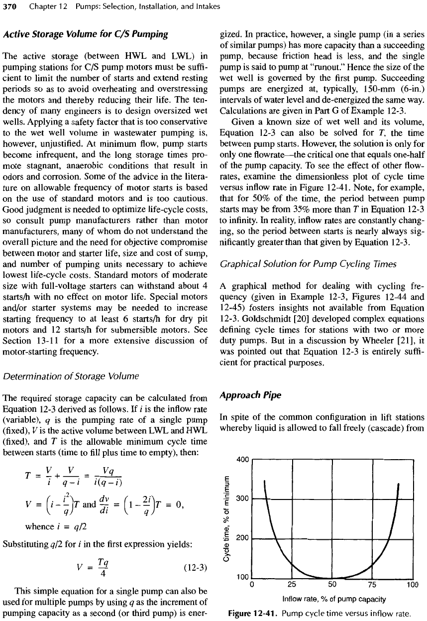
Figure
12-40)
is
placed
under each suction bell
to
eliminate
floor
vortices
and
reduce
any
tendency
for
swirling.
If
there
is an
objection
to the use of a
cone,
the floor
clearance
should
be
increased
to
D/2,
but
then wall vortices,
strong
floor
vortices,
and
swirling
can
occur. Wall
vortices disappear when
the floor
clearance
is
less
thanD/3.
h.
Intakes
may be
spaced
as
close
as
2.50
D
center
to
center,
but the
spacing must leave enough room
around machinery
for
ease
in
maintenance.
A
clear
space
of at
least
1 m (36
in.)
on
each
of
three
sides
is
a
minimum,
and
l.lm
(42
in.)
is
better,
i. The
last pump intake clears
the end
wall
by,
prefer-
ably,
no
more than
D
/4
to
inhibit surface vortices.
An
anti-rotation
baffle
somewhat similar
to
that
in
Figure 12-33
is
desirable.
Figure
12-40.
Cone
with
attached
vane
for
clean
water,
(a)
Section
B-B;
(b)
Section
A-A.
Active
Storage
Volume
for C/S
Pumping
The
active storage (between
HWL and
LWL)
in
pumping
stations
for C/S
pump motors must
be
suffi-
cient
to
limit
the
number
of
starts
and
extend resting
periods
so as to
avoid overheating
and
overstressing
the
motors
and
thereby reducing their
life.
The
ten-
dency
of
many engineers
is to
design oversized
wet
wells.
Applying
a
safety
factor
that
is too
conservative
to the wet
well volume
in
wastewater pumping
is,
however,
unjustified.
At
minimum
flow,
pump starts
become infrequent,
and the
long storage times pro-
mote stagnant, anaerobic conditions that result
in
odors
and
corrosion. Some
of the
advice
in the
litera-
ture
on
allowable frequency
of
motor starts
is
based
on the use of
standard motors
and is too
cautious.
Good judgment
is
needed
to
optimize life-cycle costs,
so
consult pump manufacturers rather than motor
manufacturers,
many
of
whom
do not
understand
the
overall picture
and the
need
for
objective compromise
between
motor
and
starter life, size
and
cost
of
sump,
and
number
of
pumping units necessary
to
achieve
lowest life-cycle costs. Standard motors
of
moderate
size with
full-voltage
starters
can
withstand about
4
starts/h
with
no
effect
on
motor
life.
Special motors
and/or starter systems
may be
needed
to
increase
starting
frequency
to at
least
6
starts/h
for dry pit
motors
and 12
starts/h
for
submersible motors.
See
Section
13-11
for a
more extensive discussion
of
motor-
starting
frequency.
Determination
of
Storage
Volume
The
required storage capacity
can be
calculated
from
Equation
12-3
derived
as
follows.
If i is the
inflow
rate
(variable),
q is the
pumping rate
of a
single pump
(fixed),
V is the
active volume between
LWL and HWL
(fixed),
and T is the
allowable minimum cycle time
between starts (time
to fill
plus time
to
empty), then:
T
-
V
+
V
-
Vq
i
q-i
i(q-i)
i/
(-
'
2
V
A
dv
(^
2/
V
n
V =
\i
— \T and — = 1
K
= O,
\
q)
di
{
q)
whence
/
= q/2
Substituting
q/2 for
/
in the first
expression yields:
V
=
^
(12-3)
This simple equation
for a
single pump
can
also
be
used
for
multiple pumps
by
using
q as the
increment
of
pumping
capacity
as a
second
(or
third pump)
is
ener-
gized.
In
practice, however,
a
single pump
(in a
series
of
similar pumps)
has
more capacity than
a
succeeding
pump,
because friction head
is
less,
and the
single
pump
is
said
to
pump
at
"runout."
Hence
the
size
of the
wet
well
is
governed
by the first
pump. Succeeding
pumps
are
energized
at,
typically,
150-mm
(6-in.)
intervals
of
water level
and
de
-energized
the
same way.
Calculations
are
given
in
Part
G of
Example
12-3.
Given
a
known size
of wet
well
and its
volume,
Equation 12-3
can
also
be
solved
for
T,
the
time
between
pump starts. However,
the
solution
is
only
for
only
one flowrate
—
the
critical
one
that equals one-half
of
the
pump capacity.
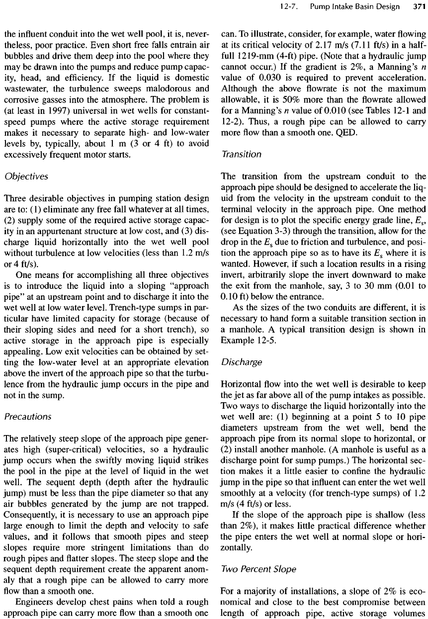
To see the
effect
of
other
flow-
rates, examine
the
dimensionless plot
of
cycle time
versus
inflow
rate
in
Figure
12-41.
Note,
for
example,
that
for 50% of the
time,
the
period between pump
starts
may be
from
35%
more than
T in
Equation 12-3
to
infinity.
In
reality,
inflow
rates
are
constantly chang-
ing,
so the
period between starts
is
nearly always sig-
nificantly
greater than that given
by
Equation
12-3.
Graphical
Solution
for
Pump
Cycling
Times
A
graphical method
for
dealing with cycling fre-
quency
(given
in
Example 12-3, Figures 12-44
and
12-45) fosters insights
not
available
from
Equation
12-3. Goldschmidt [20] developed complex equations
defining
cycle times
for
stations with
two or
more
duty
pumps.
But in a
discussion
by
Wheeler
[21],
it
was
pointed
out
that Equation 12-3
is
entirely
suffi-
cient
for
practical purposes.
Approach
Pipe
In
spite
of the
common configuration
in
lift
stations
whereby
liquid
is
allowed
to
fall
freely
(cascade)
from
Figure
12-41.
Pump
cycle
time
versus
inflow
rate.
the
influent
conduit into
the wet
well pool,
it is,
never-
theless, poor practice. Even short
free
falls
entrain
air
bubbles
and
drive them deep into
the
pool where they
may
be
drawn into
the
pumps
and
reduce pump capac-
ity,
head,
and
efficiency.
If the
liquid
is
domestic
wastewater,
the
turbulence sweeps malodorous
and
corrosive gasses into
the
atmosphere.
The
problem
is
(at
least
in
1997) universal
in wet
wells
for
constant-
speed pumps where
the
active storage requirement
makes
it
necessary
to
separate high-
and
low-water
levels
by,
typically, about
1 m (3 or 4 ft) to
avoid
excessively
frequent
motor starts.
Objectives
Three desirable objectives
in
pumping station design
are to: (1)
eliminate
any
free
fall
whatever
at all
times,
(2)
supply some
of the
required active storage capac-
ity
in an
appurtenant structure
at low
cost,
and (3)
dis-
charge liquid horizontally into
the wet
well pool
without
turbulence
at low
velocities (less than
1.2 m/s
or 4
ft/s).
One
means
for
accomplishing
all
three objectives
is
to
introduce
the
liquid into
a
sloping "approach
pipe"
at an
upstream point
and to
discharge
it
into
the
wet
well
at low
water level. Trench-type sumps
in
par-
ticular have limited capacity
for
storage (because
of
their
sloping sides
and
need
for a
short trench),
so
active
storage
in the
approach pipe
is
especially
appealing.
Low
exit
velocities
can be
obtained
by
set-
ting
the
low-water level
at an
appropriate elevation
above
the
invert
of the
approach pipe
so
that
the
turbu-
lence
from
the
hydraulic jump occurs
in the
pipe
and
not in the
sump.
Precautions
The
relatively steep slope
of the
approach pipe gener-
ates high (super-critical) velocities,
so a
hydraulic
jump occurs when
the
swiftly
moving liquid strikes
the
pool
in the
pipe
at the
level
of
liquid
in the wet
well.
The
sequent depth (depth
after
the
hydraulic
jump)
must
be
less than
the
pipe diameter
so
that
any
air
bubbles generated
by the
jump
are not
trapped.
Consequently,
it is
necessary
to use an
approach pipe
large enough
to
limit
the
depth
and
velocity
to
safe
values,
and it
follows
that smooth pipes
and
steep
slopes require more stringent limitations than
do
rough
pipes
and flatter
slopes.
The
steep slope
and the
sequent
depth requirement create
the
apparent anom-
aly
that
a
rough pipe
can be
allowed
to
carry more
flow
than
a
smooth one.
Engineers develop chest pains when told
a
rough
approach pipe
can
carry more
flow
than
a
smooth
one
can.
To
illustrate, consider,
for
example, water
flowing
at
its
critical
velocity
of
2.17
m/s
(7.1
1
ft/s)
in a
half-
full
1219-mm
(4-ft)
pipe. (Note that
a
hydraulic jump
cannot occur.)
If the
gradient
is 2%, a
Manning's
n
value
of
0.030
is
required
to
prevent acceleration.
Although
the
above
flowrate is not the
maximum
allowable,
it is 50%
more than
the flowrate
allowed
for
a
Manning's
n
value
of
0.010
(see Tables
12-1
and
12-2). Thus,
a
rough pipe
can be
allowed
to
carry
more
flow
than
a
smooth one. QED.
Transition
The
transition
from
the
upstream conduit
to the
approach
pipe
should
be
designed
to
accelerate
the
liq-
uid
from
the
velocity
in the
upstream conduit
to the
terminal velocity
in the
approach pipe.
One
method
for
design
is to
plot
the
specific
energy grade
line,
E
8
,
(see Equation 3-3) through
the
transition, allow
for the
drop
in the
E
8
due to
friction
and
turbulence,
and
posi-
tion
the
approach pipe
so as to
have
its
E
8
where
it is
wanted. However,
if
such
a
location results
in a rising
invert,
arbitrarily slope
the
invert downward
to
make
the
exit
from
the
manhole, say,
3 to 30 mm
(0.01
to
0.10
ft)
below
the
entrance.
As the
sizes
of the two
conduits
are
different,
it is
necessary
to
hand
form
a
suitable transition section
in
a
manhole.
A
typical transition design
is
shown
in
Example
12-5.
Discharge
Horizontal
flow
into
the wet
well
is
desirable
to
keep
the jet as far
above
all of the
pump intakes
as
possible.
Two
ways
to
discharge
the
liquid horizontally into
the
wet
well are:
(1)
beginning
at a
point
5 to 10
pipe
diameters upstream
from
the wet
well, bend
the
approach pipe
from
its
normal slope
to
horizontal,
or
(2)
install another manhole.
(A
manhole
is
useful
as a
discharge point
for
sump pumps.)
The
horizontal sec-
tion makes
it a
little
easier
to
confine
the
hydraulic
jump
in the
pipe
so
that
influent
can
enter
the wet
well
smoothly
at a
velocity (for trench-type sumps)
of
1.2
m/s (4
ft/s)
or
less.
If
the
slope
of the
approach pipe
is
shallow (less
than
2%),
it
makes little practical
difference
whether
the
pipe enters
the wet
well
at
normal slope
or
hori-
zontally.
Two
Percent Slope
For a
majority
of
installations,
a
slope
of 2% is
eco-
nomical
and
close
to the
best compromise between
length
of
approach pipe, active storage volumes
between high-
and
low-water levels,
and
limitation
of
the
super-critical velocities within
the
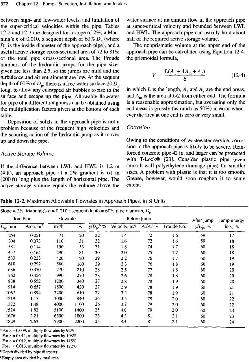
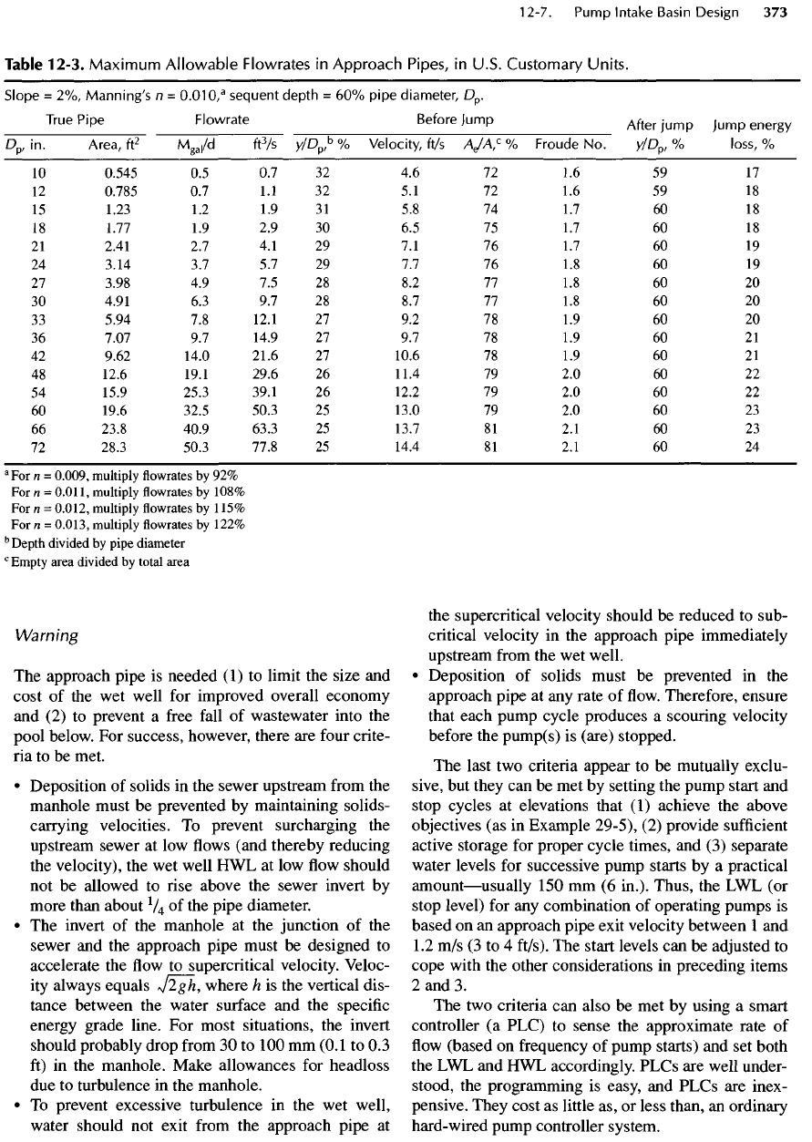
pipe. Tables
12-2
and
12-3
are
designed
for a
slope
of 2%, a
Man-
ning's
n of
0.010,
a
sequent depth
of 60%
D
p
(where
D
p
is the
inside diameter
of the
approach pipe),
and a
useful
active storage cross-sectional area
of 72 to 81%
of
the
total pipe cross-sectional area.
The
Froude
numbers
of the
hydraulic jumps
for the
pipe sizes
given
are
less than 2.5,
so the
jumps
are
mild
and the
turbulence
and air
entrainment
are
low.
At the
sequent
depth
of 60% of
D
pJ
there
is a
free
water surface
20
D
p
long,
to
allow
any
entrapped
air
bubbles
to
rise
to the
surface
and
escape
up the
pipe. Allowable
flowrates
for
pipe
of a
different
roughness
can be
obtained using
the
multiplication
factors
given
at the
bottom
of
each
table.
Deposition
of
solids
in the
approach pipe
is not a
problem because
of the
frequent high velocities
and
the
scouring action
of the
hydraulic jump
as it
moves
up
and
down
the
pipe.
Active
Storage
Volume
If
the
difference
between
LWL and HWL is 1.2
m
(4
ft),
an
approach pipe
at a 2%
gradient
is 61 m
(200
ft)
long plus
the
length
of
horizontal pipe.
The
active
storage volume equals
the
volume above
the
water
surface
at
maximum
flow in the
approach pipe
at
super-critical velocity
and
bounded between
LWL
and
HWL.
The
approach pipe
can
usually hold about
half
of the
required active storage volume.
The
nonprismatic
volume
at the
upper
end of the
approach pipe
can be
calculated using Equation
12-4,
the
prismoidal formula,
y
=
L(A
1
+
4A
m
+
A
2
)
6
in
which
L is the
length,
A
1
and
A
2
are the end
areas,
and
A
m
is the
area
at L/2
from
either end.
The
formula
is
a
reasonable approximation,
but
averaging only
the
end
areas
is
grossly
(as
much
as
50%)
in
error when-
ever
the
area
at one end is
zero
or
very small.
Corrosion
Owing
to the
conditions
of
wastewater
service,
corro-
sion
in the
approach pipe
is
likely
to be
severe. Rein-
forced
concrete pipe
42 in. and
larger
can be
protected
with
T-Lock®
[23].
Consider plastic pipe (even
smooth-wall polyethylene drainage pipe)
for
smaller
sizes.
A
problem with plastic
is
that
it is too
smooth.
Grease, however, would soon roughen
it to
some
extent.
Table
12-2.
Maximum
Allowable
Flowrates
in
Approach
Pipes,
in Sl
Units
Slope
= 2%,
Manning's
n =
0.010,
a
sequent
depth
= 60%
pipe
diameter,
D
p
.
True
p
'P
e
Flowrate
Before
Jump
After
jump
Jump
energy
Dp,
mm
Area,
m
2
m
3
/h
L/s
y/D
p
,
b
%
Velocity,
m/s
AJA,
c
%
Froude
No.
y/D
p
,
%
loss,
%
254
0.051
71 20 32 1.4 72 1.6 59 17
304
0.073
110 31 32 1.6 72 1.6 59 18
381
0.114
190 53 31 1.8 74 1.7 60 18
457
0.164
290 81 30 2.0 75 1.7 60 18
533
0.223
420 120 29 2.2 76 1.7 60 19
610
0.292
580 160 29 2.3 76 1.8 60 19
686
0.370
770 210 28 2.5 77 1.8 60 20
762
0.456
990 270 28 2.6 78 1.8 60 20
838
0.552
1200
340 27 2.8 78 1.9 60 20
914
0.657
1500
420 27 2.9 78 1.9 60 21
1067
0.894
2200
610 27 3.2 78 1.9 60 21
1219 1.17
3000
840 26 3.5 79 2.0 60 22
1372 1.48
4000
1100
26 3.7 79 2.0 60 22
1524 1.82 5100 1400
25 4.0 79 2.0 60 23
1676 2.21
6500
1800
25 4.2 81 2.1 60 23
1829 2.63
7900
2200
25 4.4 81 2.1 60 24
a
For n =
0.009,
multiply
flowrates by 92%
For n =
0.011,
multiply
flowrates by
108%
For n =
0.012,
multiply
flowrates by
115%
For
n -
0.013,
multiply
flowrates
by
122%
b
Depth
divided
by
pipe
diameter
c
Empty
area
divided
by
total
area
Warning
The
approach pipe
is
needed
(1)
to
limit
the
size
and
cost
of the wet
well
for
improved overall economy
and
(2) to
prevent
a
free
fall
of
wastewater into
the
pool below.
For
success, however, there
are
four
crite-
ria
to be
met.
•
Deposition
of
solids
in the
sewer upstream
from
the
manhole must
be
prevented
by
maintaining solids-
carrying
velocities.
To
prevent surcharging
the
upstream sewer
at low flows
(and thereby reducing
the
velocity),
the wet
well
HWL at low flow
should
not
be
allowed
to
rise above
the
sewer invert
by
more than about
l
/
4
of the
pipe diameter.
• The
invert
of the
manhole
at the
junction
of the
sewer
and the
approach pipe must
be
designed
to
accelerate
the flow to
supercritical velocity. Veloc-
ity
always equals
J2gh,
where
h is the
vertical dis-
tance between
the
water surface
and the
specific
energy
grade line.
For
most situations,
the
invert
should probably drop
from
30 to 100 mm
(0.1
to 0.3
ft)
in the
manhole. Make allowances
for
headloss
due
to
turbulence
in the
manhole.
• To
prevent excessive turbulence
in the wet
well,
water
should
not
exit
from
the
approach pipe
at
the
supercritical velocity should
be
reduced
to
sub-
critical velocity
in the
approach
pipe
immediately
upstream
from
the wet
well.
•
Deposition
of
solids must
be
prevented
in the
approach pipe
at any
rate
of flow.
Therefore, ensure
that
each pump cycle produces
a
scouring velocity
before
the
pump(s)
is
(are) stopped.
The
last
two
criteria appear
to be
mutually exclu-
sive,
but
they
can be met by
setting
the
pump start
and
stop cycles
at
elevations that
(1)
achieve
the
above
objectives
(as in
Example 29-5),
(2)
provide
sufficient
active storage
for
proper cycle times,
and (3)
separate
water levels
for
successive pump starts
by a
practical
amount
—
usually
150 mm (6
in.).
Thus,
the LWL (or
stop level)
for any
combination
of
operating pumps
is
based
on an
approach pipe exit velocity between
1 and
1.2 m/s (3 to 4
ft/s).
The
start levels
can be
adjusted
to
cope with
the
other considerations
in
preceding items
2 and 3.
The two
criteria
can
also
be met by
using
a
smart
controller
(a
PLC)
to
sense
the
approximate rate
of
flow
(based
on
frequency
of
pump starts)
and set
both
the LWL and HWL
accordingly. PLCs
are
well under-
stood,
the
programming
is
easy,
and
PLCs
are
inex-
pensive. They cost
as
little
as, or
less than,
an
ordinary
hard-
wired
pump controller system.
Table
12-3.
Maximum
Allowable
Flowrates
in
Approach
Pipes,
in
U.S.
Customary
Units.
Slope
= 2%,
Manning's
n =
0.010,
a
sequent
depth
= 60%
pipe
diameter,
D
p
.
True
pi
P
e
Flowrate
Before
Jump
After
jump
Jump energy
D
p/
in.
Area,
ft
2
M
ga
,/d
ft
3
/s
y/D
p
,
b
%
Velocity,
ft/s
AJA,
C
%
Froude
No.
y/D
p
,%
loss,
%
10
0.545
0.5 0.7 32 4.6 72 1.6 59 17
12
0.785
0.7 1.1 32 5.1 72 1.6 59 18
15
1.23
1.2 1.9 31 5.8 74 1.7 60 18
18
1.77
1.9 2.9 30 6.5 75 1.7 60 18
21
2.41
2.7 4.1 29 7.1 76 1.7 60 19
24
3.14
3.7 5.7 29 7.7 76 1.8 60 19
27
3.98
4.9 7.5 28 8.2 77 1.8 60 20
30
4.91
6.3 9.7 28 8.7 77 1.8 60 20
33
5.94
7.8
12.1
27 9.2 78 1.9 60 20
36
7.07
9.7
14.9
27 9.7 78 1.9 60 21
42
9.62 14.0 21.6
27
10.6
78 1.9 60 21
48
12.6 19.1 29.6
26
11.4
79 2.0 60 22
54
15.9 25.3 39.1
26
12.2
79 2.0 60 22
60
19.6 32.5 50.3
25
13.0
79 2.0 60 23
66
23.8 40.9 63.3
25
13.7
81 2.1 60 23
72
28.3 50.3 77.8
25
14.4
81 2.1 60 24
a
For
n =
0.009,
multiply
flowrates by 92%
For n =
0.011,
multiply
flowrates by
108%
For n =
0.012,
multiply
flowrates by
115%
For n =
0.013,
multiply
flowrates by
122%
b
Depth divided
by
pipe diameter
c
Empty area divided
by
total area
