Pumping Station Desing - Second Edition by Robert L. Sanks, George Tchobahoglous, Garr M. Jones
Подождите немного. Документ загружается.

supports should
be
designed
for
natural frequencies
well
above
the
highest operating speed. Always con-
duct
a
dynamic analysis
of the
structure
as
part
of the
design
process.
Don't
forget that some equipment
vendors have
offerings
that
differ
substantially
in
terms
of
operating speed, weight, number
of
impeller
and
diffuser
vanes
or
cylinders
and
other important
features.
Make certain
all
variations
are
considered
in
the
design.
All
equipment should
be
placed
on
housekeeping
pads. Housekeeping pads
are
concrete bases raised
above
the floor by a
minimum
of 100 mm (4
in.).
The
purpose
of
these pads
is to
prevent liquids
on the floor
from
accumulating against
ferrous
metal
and
causing
corrosion.
All
equipment should
be
grouted
in
place
after
shimming between
the
equipment
and the pad to
make certain
it is
supported
and
leveled properly.
Large pieces
of
equipment should
be
installed
on
grouted-in
sole
plates
furnished
by the
manufacturer.
Only journeyman millwrights should
be
allowed
to
perform
final
alignment. Alignment methods should
be
those recommended
and
accepted
by the
manufacturer.
Maintenance
Access
Access
for
maintenance
is an
important aspect
of
installation design. Ensure
at
least
1.1
m
(3.5
ft)
clear
between adjacent pieces
of
equipment. Provide more
clearance with large units. Vertical clearance over
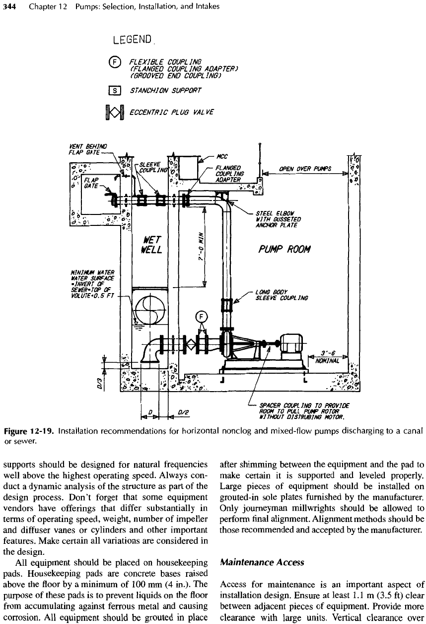
Figure
12-19.
Installation recommendations
for
horizontal
nonclog
and
mixed-flow
pumps discharging
to a
canal
or
sewer.
walkways
and
adjacent
to
major
items
of
equipment
should
be not
less than
2.3 m
(7.5 ft). Make certain
there
is
sufficient
clear space around
the
equipment
to
remove subassemblies. Hoisting equipment should
be
provided
in all
stations where
the
largest individual
equipment unit subassembly weighs more than
90 kg
(200
Ib).
Electrified
hoist, trolley,
and
bridge
functions
are
recommended
for all
hoist capacities greater than
about
900 kg
(2000
Ib).
Make certain
the
installation
is
designed
to
provide
vertical hoist access
to all
large equipment compo-
nents.
Use
lifting
hooks over equipment only
as a
last
resort. Cranes
are
much better than hoists
and
should
be
arranged
to
deliver
the
largest single equipment
component directly
to the bed of a
service truck. Avoid
arrangements
where service personnel
are
required
to
place components
on a
dolly
and
manually move them
to
another position
for
later placement
on a
truck bed.
System
Controls
Remember that
the
controls
for a
pumping installation
are not for
merely controlling
a set of
pumps,
but
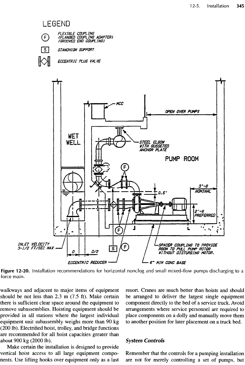
Figure
12-20.
Installation
recommendations
for
horizontal
nonclog
and
small
mixed-flow
pumps discharging
to a
force
main.
rather
a
whole system.
For
that reason,
it is
important
to
consider
the
effects
of
operation
of the
equipment
on
other parts
of the
total installation, such
as:
•
Operation
of too
much pumping capacity (such
as a
standby
pump along
with
all
others)
may
overload
a
downstream
system such
as a
receiving sewer
or
storm
channel.
•
Constant-speed operation
may be
inappropriate
for
the
function
of
downstream treatment operations.
• If a
pumping unit includes high-inertia components,
quick restarting
after
loss
of
power while
the
equip-
ment
is
still rotating
may
cause considerable dam-
age to
shafts,
couplings, motor windings,
and
other
components.
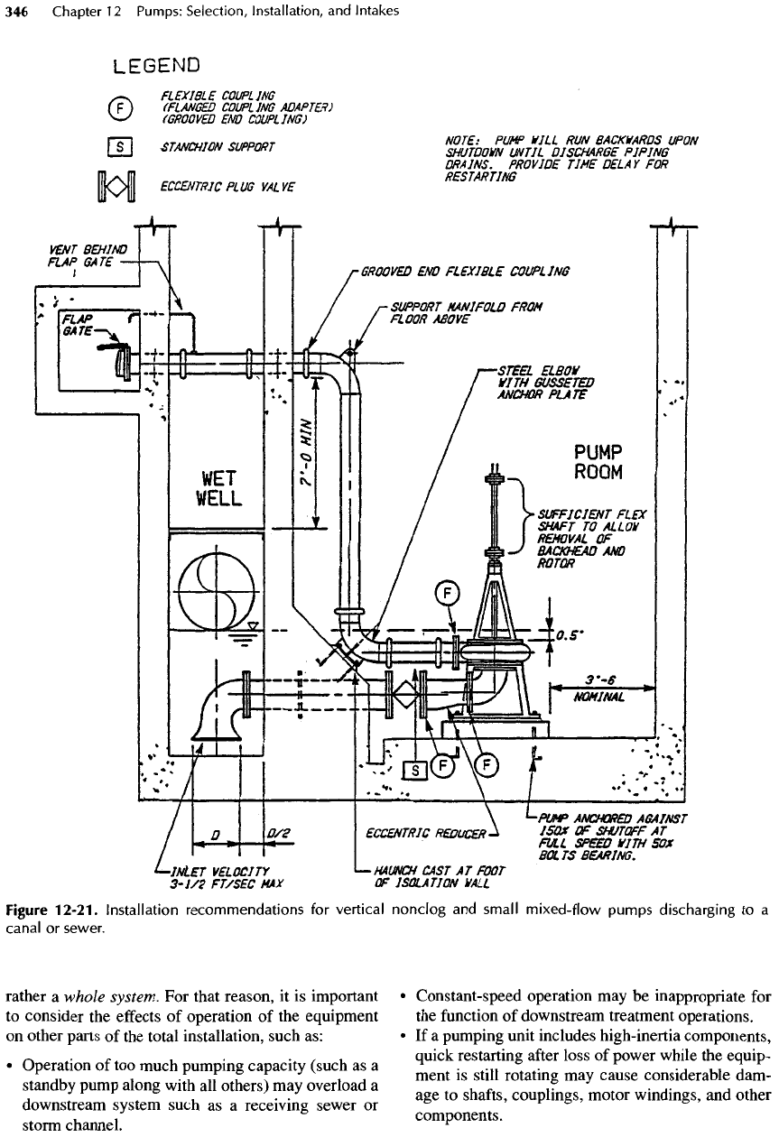
Figure
12-21.
Installation
recommendations
for
vertical
nonclog
and
small
mixed-flow
pumps discharging
to a
canal
or
sewer.
•
Some pumps, such
as
column pumps, will spin back-
ward
when stopped. Even
if a
nonreverse
device
has
been installed,
countertorque
will
act on the
shaft
until
the
column
has
been emptied. Starting
the
pump
with
a
full
column
may
cause considerable damage,
so
arrange
the
controls
to
lock
out the
starter until
the
column
is
empty. Confer with
the
manufacturer
for
finding
means
to
circumvent these problems.
Environmental
Considerations
For the
most part, utility installations should
not be
seen, heard,
or
detected
in any way
that would
degrade
the
local environment.
The
design
of
utility
installations should include
the
following features:
•
Architectural design that blends into
the
neighbor-
hood
and
neither establishes
a
presence that
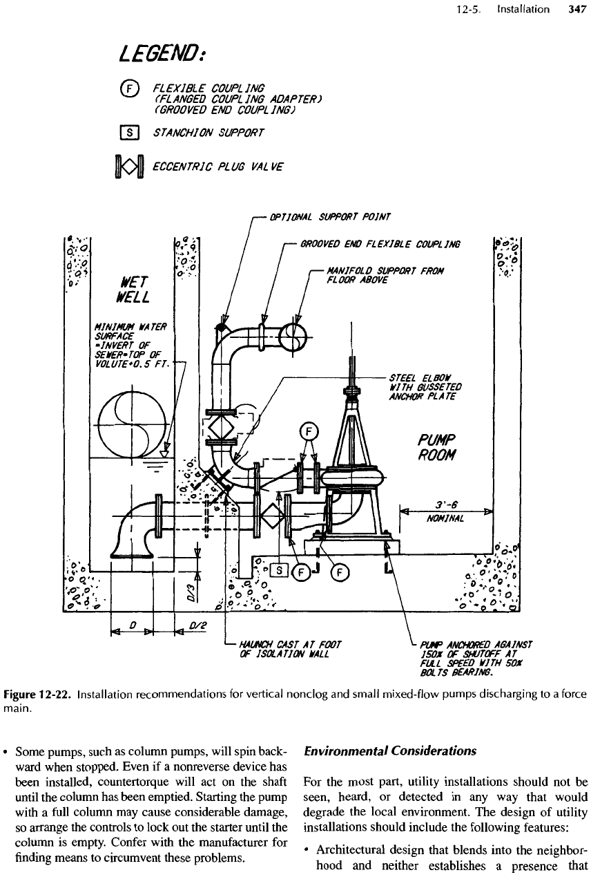
Figure
12-22.
Installation recommendations
for
vertical
nonclog
and
small
mixed-flow
pumps discharging
to a
force
main.
declares
the
purpose
of the
installation
nor
degrades
the
value
of its
neighbors.
Pumping station super-
structures
can, with minimal
effort
and
expense,
easily
be
crafted
to
appear
to be
homes,
farm-
houses,
or
restaurants.
•
Noise
and
light emissions suppressed
to
avoid
broadcasting
the
function
of the
installation. Spe-
cial construction features
can be
included
to
elimi-
nate
virtually
all of the
high-frequency noise
from
motors. Hospital-grade silencers
are
available
for
engines
at
little additional cost. With diligence,
the
noise
from
ventilation equipment
can
also
be
sup-
pressed. Lighting
fixtures
in a
variety
of
architectur-
ally
acceptable
designs
are
available
to
illuminate
exterior areas without suggesting
a
commercial
or
industrial facility.
•
Odor control
and
treatment
for
wastewater stations.
Odor control
is,
perhaps,
the
most challenging envi-
ronmental management task.
The
design should
incorporate every technique
for
avoiding
the
condi-
tions that generate odors. Ventilation system
exhausts
should
be
treated
for
odor removal.
A
vari-
ety of
cost-effective
and
simple odor treatment
techniques
are
available (see Chapter 23).
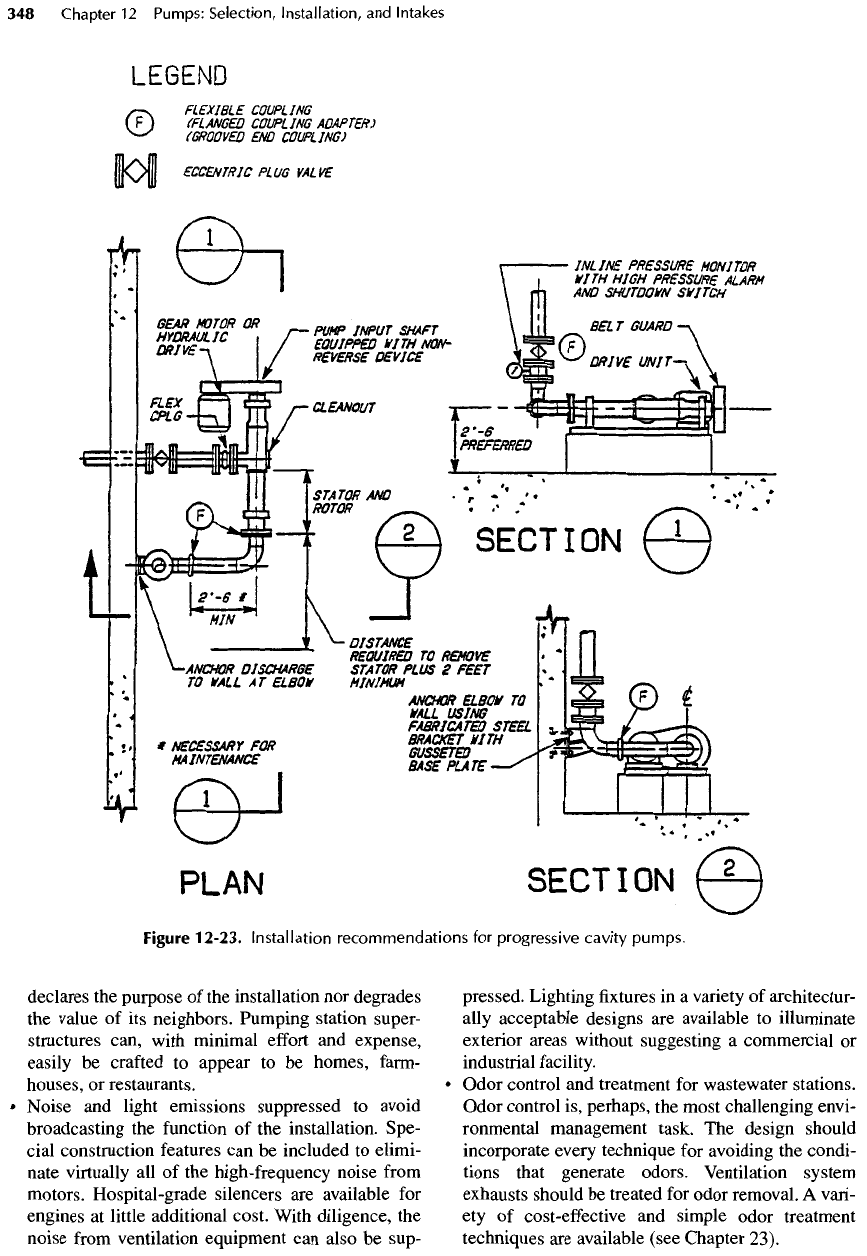
Figure
12-23. Installation recommendations
for
progressive cavity pumps.
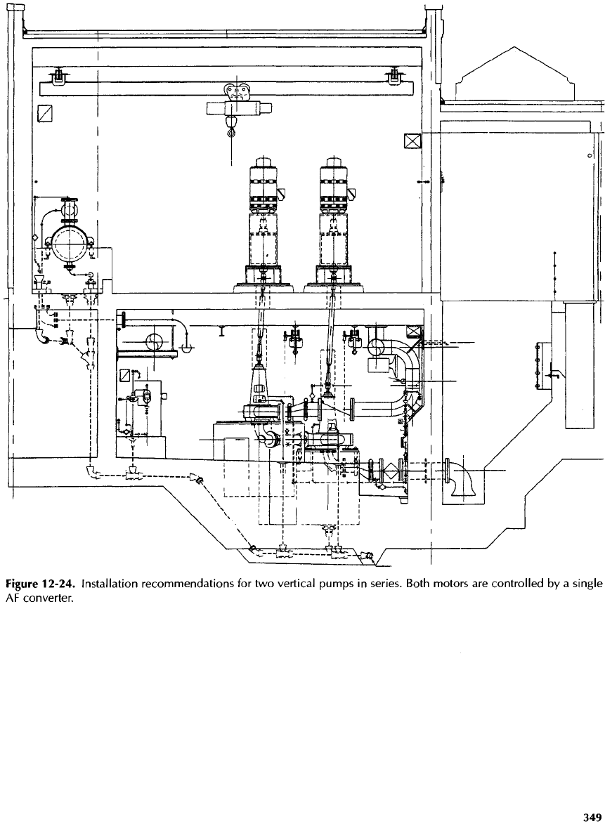
Figure
12-24. Installation recommendations
for two
vertical pumps
in
series.
Both motors
are
controlled
by a
single
AF
converter.
Service
Piping
and
Appurtenances
Care should
be
taken
to
avoid cluttering equipment
maintenance
points with service piping, conduits,
and
other peripheral devices
and
fixtures.
If
gauges
are
necessary, they should
be
mounted
on
walls
or
gauge
boards located away
from
the
pump itself. Purge pan-
els for
packing
boxes
or
mechanical
seals
should
be
located
on
walls
or
columns
and the
service piping
(stainless steel) routed
in
slabs
to the
pump house-
keeping pad. Every
effort
should
be
made
to
keep
the
equipment
installation clean
and
free
from
items that
could
interfere
with
maintenance operations.
12-6.
Pump
Intake
Basins:
An
Appraisal
The
head-capacity curves
for
pumps developed
by the
pump
manufacturer
are
based
on
tests
of a
single
pump
operating
in a
semi-infinite pool with
no
nearby
walls
or floors and no
stray currents. Hence,
flow
into
the
pump suction
is
symmetrical with
no
vortices
or
swirling
(prerotation). Pumping station designers rely
on
these curves
to
define
the
operating
conditions
for
the
pumps selected.
But
various constraints such
as
size,
cost, limitations
on
storage time,
and
(for solids-
bearing waters) deposition require walls,
floors, and
pump
intakes
to be in
close proximity
to
each other.
As
the
manufacturer's test conditions cannot
be
dupli-
cated
in the field,
various problems arise
and
many
designs,
in
spite
of
their common
acceptance
and
con-
tinual
usage,
do not
perform well.
The
BHRA
[1]
recommendations
and (in the
United States)
the
Hydraulic Institute Standards
[2, 3,
4] are
considered
to be the
authoritative works
for the
design
of
pump intakes. However,
up to and
includ-
ing
the
1994
edition
of the
Hydraulic Institute Stan-
dards
(as
well
as the
BHRA
publication),
the
focus
has
been largely
confined
to
clear water, with discus-
sion
on
solids-bearing
water
essentially
limited
to the
advice that
flat floor
areas should
be
minimized, that
designs proven
to be
successful should
be
followed,
or
that pump manufacturers should
be
consulted.
In
1994,
the
Hydraulic Institute appointed
a
committee
of
users, engineering consultants, researchers,
and
pumping equipment producers
to
expand
and
improve
the
standards
for
clear
water and,
for the first
time,
to
consider designs
for
solids-bearing waters
in
detail.
The
material
in
this chapter
and the
proposed
standards
are
mutually compatible
and
complemen-
tary.
Furthermore,
the
presentation
in
this chapter
reflects:
(1)
experience
gained through more than
35
years
of
designing pumping station
wet
wells;
(2)
information
developed
at the
U.S. Corps
of
Engineers
Waterways
Experiment Station
in
Vicksburg;
(3)
investigations
at
Montana
State
University
and
ENSR
Hydraulic
Laboratory
in
Redmond, Washington,
under
financial
assistance
from
the
U.S. Environmen-
tal
Protection Agency,
The
Gorman-Rupp
Co.,
Fair-
banks Morse Pump Corp.,
ITT
Flygt
AB;
Montana
State University,
and R. L.
Sanks;
and (4)
full-scale
tests
at the
Fairbanks Morse Pump Corp. plant
in
Kansas
City
—
all
of
which have
led to
several
publi-
cations
[5, 6, 7,
8].
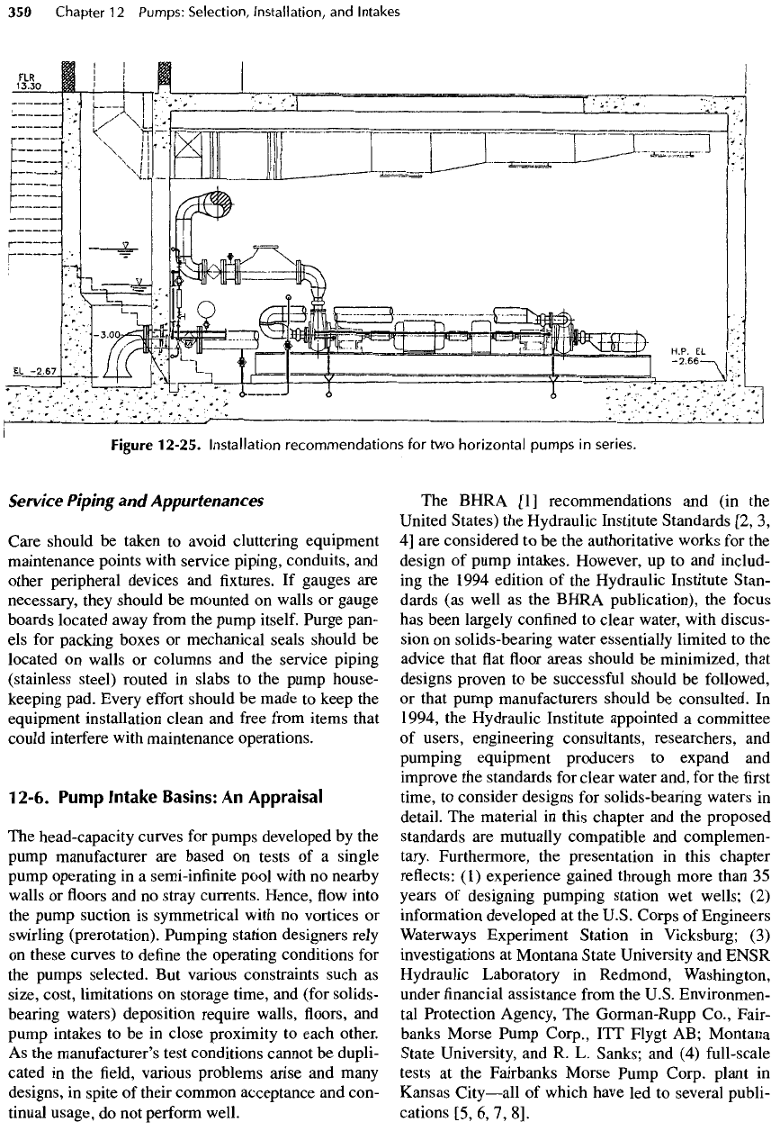
Figure
12-25.
Installation
recommendations
for two
horizontal
pumps
in
series.
Pump
Sump Problems
The
geometry
of the
pump sump
and its
associated
piping
and
entrance conditions
has a
profound
effect
on
pump performance. Hydraulic
conditions
detri-
mental
to
pump performance include:
•
Asymmetrical velocities
in the
approach
to the
pump
intake
•
Nonuniform
or
asymmetrical velocity distribution
in
the
pump intake
•
Swirling
or
prerotation
of flow at the
impeller
•
Surface
and
subsurface vortices.
Asymmetrical
flow to a
pump intake
is
likely
to
pro-
duce
swirling and/or asymmetrical velocity distribution
in
the
intake throat. Asymmetrical velocities
in the
intake throat create
a
higher load
on one
side
of the
impeller, bend
the
shaft,
and put
extra stress
on
bearings
and
couplings. They
can
cause rough operation, vibra-
tion,
and
loss
of
head
and
capacity.
These
effects
worsen
as
pumps
get
larger
and as the
specific
speed
increases.
Swirling
changes
the
angle
of
attack
on the
impel-
ler
vanes,
reduces
head
and
capacity,
and
decreases
efficiency.
An
angle
of 5°
from
axial
is
usually consid-
ered
the
maximum allowable. Swirling
in the
approach
can
degenerate
into
vortices.
The
pressure
in
the
core
of a
vortex
is
reduced
and air (or
other gasses)
coming
out of
solution
can
cause noisy operation
and
vibration. When
a
vortex
is
severe,
it
results
in
cavita-
tion
that quickly erodes metals.
Strong surface vortices entrain
air
bubbles that col-
lapse
as
they pass
from
low to
high
pressure
zones
across
the
impeller vane, thus creating
noise,
uneven
torque,
undue stress
on
shafts
and
couplings,
and
ero-
sion.
A
small amount
of air can
cause
a
large
decrease
of
capacity, head,
and
efficiency.
Milder surface vorti-
ces
tend
to
become smaller
but
more intense
as
they
enter
the
intake.
Strong
subsurface
vortices,
formed
as
liquid sepa-
rates
from
walls
or floors, are
often
present
and
difficult
or
impossible
to
detect
in the field.
Normally,
the
bub-
bles
in
subsurface
vortices consist
of air
that comes
out
of
solution
due to the
decreased pressure
in the
core.
Subsurface
vortices
are
just
as
damaging
as
surface vor-
tices
—
sometimes
more
so. If
vapor bubbles
can
form,
they
cause rapid erosion.
In
fact,
the
rate
of
erosion
can
be
reduced (although performance
is
also reduced)
by
introducing
air
deliberately
to
form
large bubbles that
do
not
completely collapse (see Section 10-4).
General
Problems
Designers should
try to
visualize
the flow
patterns
likely
to
develop
in a
sump.
The
mental picture
may
be
somewhat inaccurate,
but
even
so, it can
serve
to
identify
potential
problems.
For
example,
let us
ana-
lyze
several types
of
sumps
by
trying
to
visualize
how
water must behave
in
each. Bear
in
mind several phe-
nomena
that govern
the flow of
water
including:
Phenomenon
1
.
Water emerging
as a jet
from
a
pipe
into
a
relatively quiescent
pool
tends
to
continue
to
flow
in
a
straight
jet
that spreads only about
one
unit
per
eight units
of
travel.
The
center
of the jet
tends
to
retain
its
original velocity
for a
consider-
able distance,
and
eddies (rotation)
are
generated
along
the
edges
of the
jet.
Phenomenon
2.
When
a jet of
water
is
forced
to
turn,
swirls
are
created
and
some energy
is
lost. Swirls
tend
to
persist
and may
develop into vortices
at
pump
intakes.
Phenomenon
3.
Vortices easily
form
in
quiescent
water both
at the
water surface
and
under water
at
walls
or floors. Low
velocities past pump intakes
tend
to
prevent swirls
from
organizing into vortices.
Specific
Examples
According
to
Hydraulic Institute Standards
[2] or the
ANSI/HI
Standards
[3, 4], the
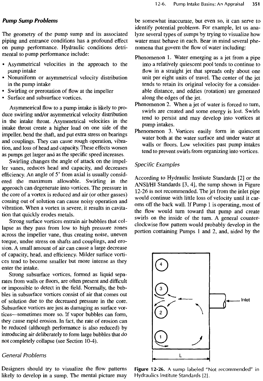
sump shown
in
Figure
12-26
is not
recommended.
The jet
from
the
inlet pipe
would
continue with little loss
of
velocity until
it
car-
oms off the
back wall.
If
Pump
1 is
operating, most
of
the flow
would turn toward that pump
and
create
swirls
on the
inside
of the
turn.
A
general counter-
clockwise
flow
pattern would probably develop
in the
portion containing Pumps
1 and 2,
and, aided
by the
Figure
12-26.
A
sump
labeled
"Not
recommended"
in
Hydraulics
Institute
Standards
[2].
incoming jet, might become quite pronounced.
On the
other hand,
if
only Pump
4
were operating,
the
water
would
turn toward that pump
and
produce
a
clockwise
current
in the
part
of the
sump containing Pumps
3
and
4. In
either regime, however,
flow to all
pumps
would
be
asymmetrical
with
respect
to a
line through
the
center
of the
pump
and
normal
to the
wall. Swirl-
ing
would probably
be
excessive because
of
Phenom-
enon
2.
The
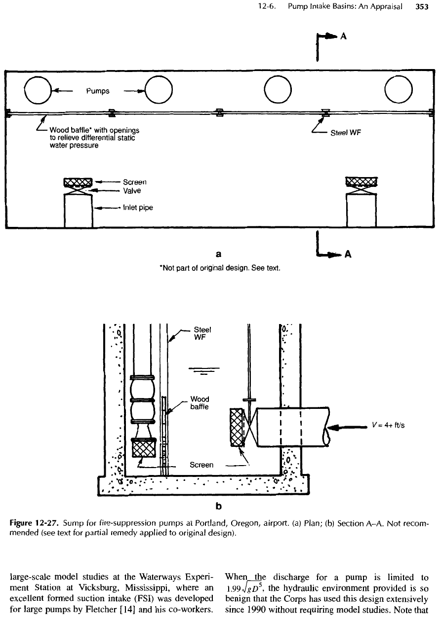
sump shown
in
Figure
12-27
(but without
the
baffle)
was
used
in a fire
suppression system
for two
huge
airplane hangars.
The
sump design
was so
poor
that
the
pumps vibrated excessively
and
could
not
meet their rated capacity.
The fire
marshall refused
to
approve
the
system. Against
the
express
recommenda-
tion
of the
pump
manufacturer,
a
consultant (guided
by
30
years
of
experience with trench-type
wet
wells)
recommended
a
submerged
baffle
to
place
the
pump
intakes
in a
trench.
As
shown
in the figure, the
trench
is
fed by
water
flowing
gently over
the top of the
baf-
fle.
Consequently,
the
circulation currents
are
destroyed, water
now
enters
the
pump intakes sym-
metrically,
the
pumps operate
at
rated capacity,
and
the
installation
was
approved.
Nevertheless,
the
sump
is
deficient
in
several other
respects
(excessive
floor
clearance under pump intakes
and
poor
inlet design,
to
name two)
and is not
recommended.
Consider
the
sump shown
in
Figure 12-28. Some
swirling along
the
edges
of the jet may be
expected
and
rotation
due to the
curvature
of the jet as it
strikes
the
end
wall
is not
entirely suppressed. Flow, espe-
cially
flow to the end
pumps,
is
asymmetrical
(although much less
so
than
in
Figure 12-26),
and the
asymmetry
may
induce swirling.
In
sumps
of
this
type,
baffle
walls have sometimes been placed
between
the
pumps
to
improve symmetry,
but the
noses
of the
baffle
wall themselves
may be a
source
of
swirling.
Furthermore,
the
submergence shown
is
inadequate
for
some installations. According
to
Sanks,
Jones,
and
Sweeney [7],
the
submergence
of the
suc-
tion
intake should
be at
least
2 D to
prevent
the
forma-
tion
of
significant
surface vortices
at
intake velocities
up
to
1.5
m/s (5
ft/s).
Dicmas
[9] has
shown that
the
submergence should
be 2.4 D in
sumps
2 D
wide
and
1.9
D in
sumps
3 D
wide. According
to
Hecker
[10],
the
intake
of air
from
surface vortices
can
only
be
entirely eliminated
at
submergences
of at
least
S
=
(1+2.3F)D
(12-1)
where
S is
submergence,
D is the
outside diameter
of
the
suction bell,
and F
(the Froude number)
is
defined
as
v(gZ))~°
5
where
v is the
average
velocity
at the
entrance
to the
bell.
On the
basis
of
Equation
12-1,
the
required submergence
is
usually
12 to 20%
more than
the
criterion
of 2 Z). A
significant
disadvantage
of the
design
in
Figure 12-28
is its
tremendous size.
If the
intake structure must
be
deep,
such
a
sump would
be
costly indeed.
It
might well
be
improved
by
making
the floor flat to
within, say,
D of the
pump intake cen-
ters
—
a
design (shown
by the
dashed lines) that puts
the
intakes
in a
trench. Then
the flow to the
intakes
would probably become more symmetrical,
and
pump
performance would likely
be
improved.
The
length
could then
be
shortened
for
economy. Such
a
modified
sump
for
pumping
37,600
m
3
/h
(238
Mgal/d)
of
set-
tled wastewater
at a
treatment plant
in
Colorado per-
forms
very well indeed.
Another
way to
improve
the
performance
of the
sump
in
Figure 12-28
is to add
long
baffles
between
the
pumps
as
described
in the
Hydraulic Institute
Standards proposed
for
publication
in
1998.
The
baf-
fles
extend
from
the end
wall
to a
point
at
least
5 D
from
the
pump. Thus each pump
is
located
in an
indi-
vidual
channel
—
a
construction that requires
a
long
sump.
Such
a
sump
is
difficult
to
keep clean
if the
water contains solids.
Extensive research
at the
Hydraulics Laboratory
of
the
U.S.
Army Corps
of
Engineers Waterways Experi-
ment Station
at
Vicksburg,
Mississippi,
resulted
in a
short
but
thorough
and
informative technical letter
[11]
for
guidance
in the
design
of wet
wells
of the
configuration
shown
in
Figure 12-28.
The
reason
for
troubles with pumps
in
such sumps
is
shown
in one of
the
figures in the
technical
letter
that
illustrates
a jet
discharging into ponded water. Means
for
circumven-
tion
are
shown
in
other
figures in the
technical letter.
Figure 12-29 represents
the
type
of
sump
in
which
water
is
required
to
change direction
by
90°, thereby
running
afoul
of
Phenomenon
2
—
a
problem that
can
be
alleviated
by
making
the
distance
L
sufficiently
great.
The
baffles
are
intended
to
straighten
the flow
and
make
it
symmetrical. Again, this design requires
a
large footprint
and
becomes
costly.
Aping
the
geometry
of
traditional designs
is no
guarantee
of
success. Triplett, Fletcher,
and
Grace
[12] emphasized
the
problems concerning some estab-
lished pump sump design criteria with their statement
in
1988 that
"approximately
50% of all
sumps
for
flood-control
pumping stations designed
and
con-
structed
by the
Corps
[of
Army Engineers] needed
some sort
of
post-
construction
modification
to
improve
the flow
conditions
to the
pumps.
These
mod-
ifications
were
costly
and in
most cases
did not
cor-
rect
the
problem
but
improved
the
conditions
only
slightly."
Criticisms such
as
this should
jar
engineers
out
of any
complacency
toward sump
design
(see
also
Karassik
et
al
[13]).
The
problems
did
lead
the
U.S.
Army Corps
of
Engineers
to
undertake extensive,
large-scale model studies
at the
Waterways Experi-
ment
Station
at
Vicksburg, Mississippi, where
an
excellent
formed suction intake (FSI)
was
developed
for
large pumps
by
Fletcher [14]
and his
co-workers.
When
the
discharge
for a
pump
is
limited
to
1.
99
Jg
Z)
5
,
the
hydraulic environment provided
is so
benign that
the
Corps
has
used this design extensively
since 1990 without requiring model studies. Note that
*Not
part
of
original design.
See
text.
Figure
12-27.
Sump
for
fire-suppression pumps
at
Portland,
Oregon,
airport,
(a)
Plan;
(b)
Section A-A.
Not
recom-
mended
(see text
for
partial
remedy
applied
to
original
design).
