Pumping Station Desing - Second Edition by Robert L. Sanks, George Tchobahoglous, Garr M. Jones
Подождите немного. Документ загружается.

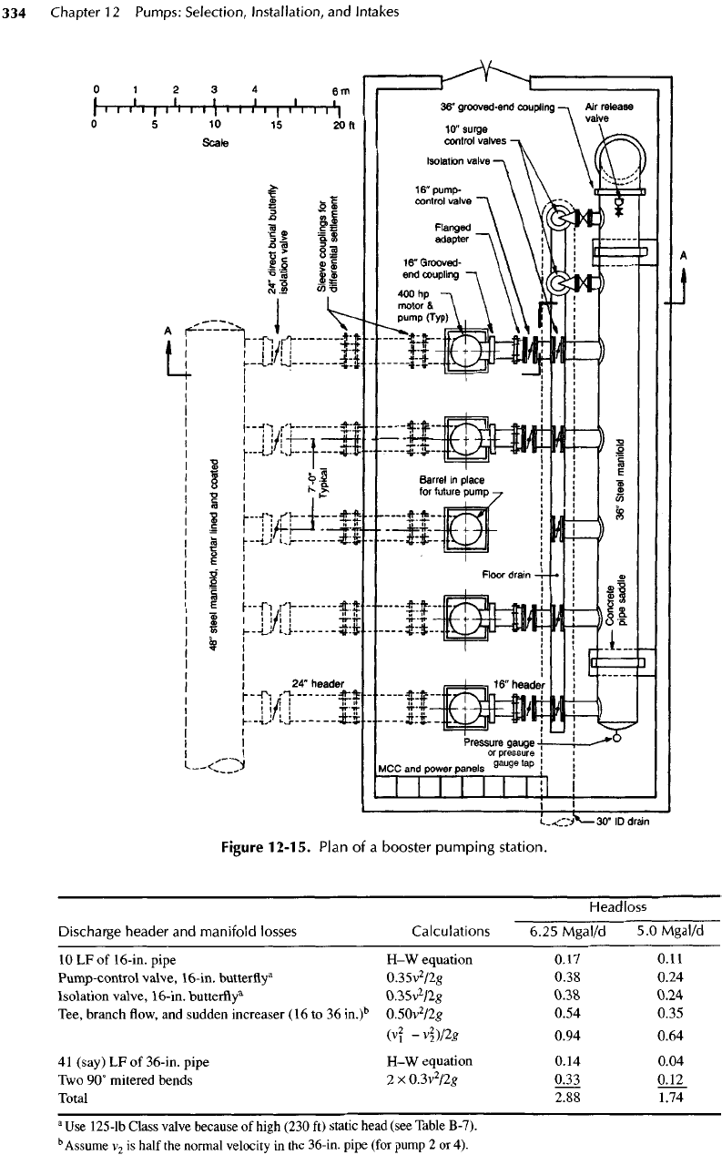
Figure
12-15.
Plan
of a
booster
pumping
station.
Headless
Discharge header
and
manifold
losses
Calculations 6.25
Mgal/d
5.0
Mgal/d
10
LF of
16-in.
pipe
H-W
equation
0.17 0.11
Pump-control
valve,
16-in.
butterfly
3
0.35v
2
/2g
0.38 0.24
Isolation
valve,
16-in.
butterfly*
035v
2
/2g
038
0.24
Tee,
branch
flow, and
sudden
increaser
(16 to 36
in.)
b
0.50v
2
/2g
0.54 0.35
(v\
-v
2
2
}!2g
0.94 0.64
41
(say)
LF of
36-in.
pipe
H-W
equation
0.14
0.04
Two
90°
mitered
bends
2x0.3v
2
/2g
0.33 0.12
Total
2.88 1.74
a
Use
125-lb
Class valve because
of
high (230
ft)
static head (see Table B-7).
b
Assume
V
2
is
half
the
normal velocity
in the
36-in. pipe (for pump
2 or 4).
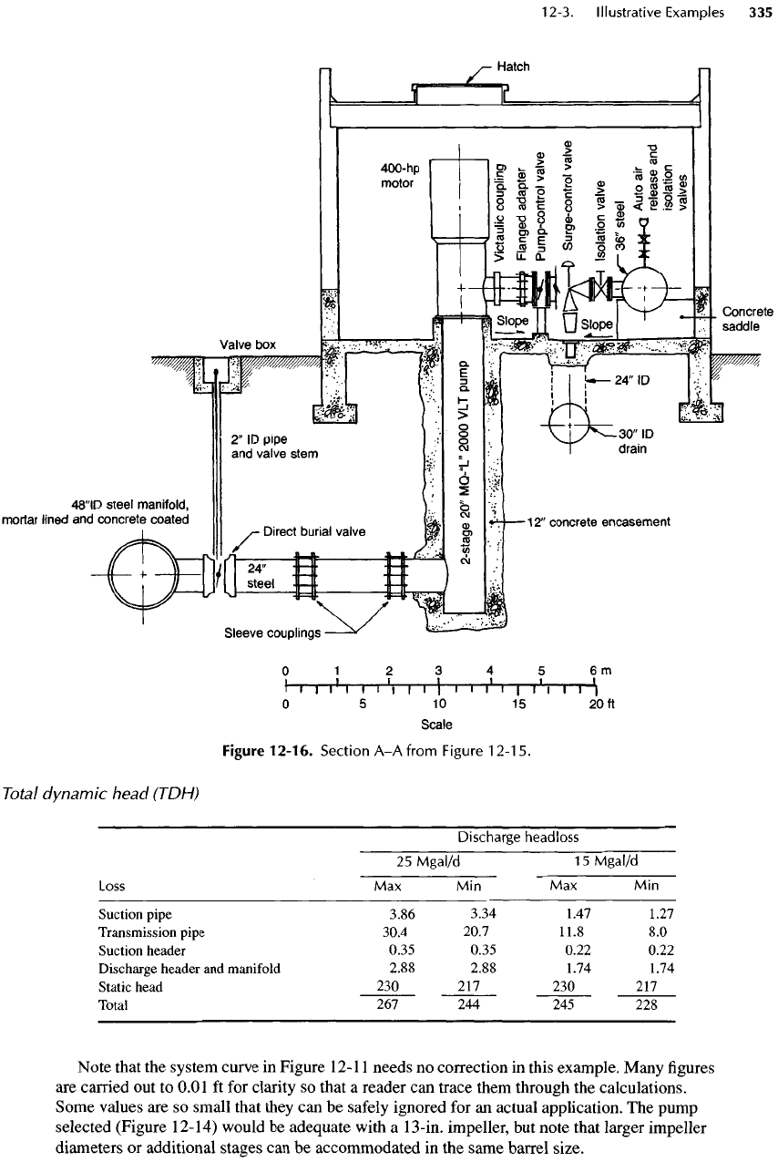
Figure
12-16.
Section
A-A
from
Figure
12-15.
Total
dynamic
head
(TDH)
Discharge
headloss
25
Mgal/d
15
Mgal/d
Loss
Max Min Max Min
Suction pipe 3.86 3.34 1.47 1.27
Transmission pipe 30.4 20.7 11.8
8.0
Suction header 0.35 0.35 0.22 0.22
Discharge header
and
manifold 2.88 2.88 1.74 1.74
Static head
230 217 230 217
Total
267 244 245 228
Note
that
the
system curve
in
Figure
12-11
needs
no
correction
in
this example. Many
figures
are
carried
out to
0.01
ft for
clarity
so
that
a
reader
can
trace them through
the
calculations.
Some values
are so
small that they
can be
safely
ignored
for an
actual application.
The
pump
selected (Figure 12-14) would
be
adequate with
a
13-in.
impeller,
but
note that larger impeller
diameters
or
additional stages
can be
accommodated
in the
same barrel size.
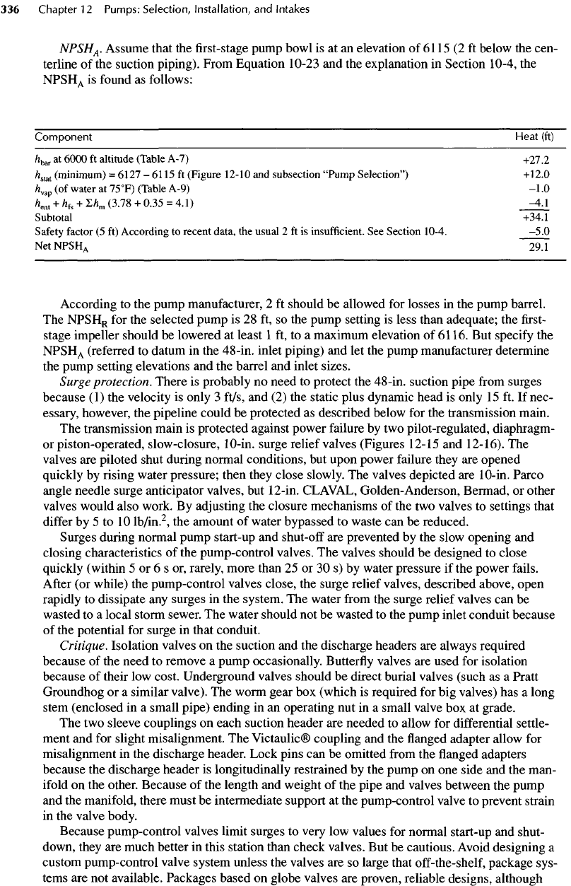
NPSH
A
.
Assume that
the first-stage
pump bowl
is at an
elevation
of
6115
(2 ft
below
the
cen-
terline
of the
suction piping). From Equation 10-23
and the
explanation
in
Section 10-4,
the
NPSH
A
is
found
as
follows:
Component Heat (ft)
h
bar
at
6000
ft
altitude
(Table
A-7)
+27.2
/z
stat
(minimum)
=
6127
-
6115
ft
(Figure
12-10
and
subsection
"Pump
Selection")
+12.0
/z
vap
(of
water
at
75
0
F)
(Table A-9)
-1.0
/z
ent
+
h
k
+
I/z
m
(3.78
+
0.35
=
4.1)
-4.1
Subtotal +34.1
Safety
factor
(5 ft)
According
to
recent
data,
the
usual
2 ft is
insufficient.
See
Section
10-4.
-5.0
Net
NPSH
A
29.1
According
to the
pump manufacturer,
2 ft
should
be
allowed
for
losses
in the
pump barrel.
The
NPSH
R
for the
selected pump
is 28 ft, so the
pump setting
is
less than adequate;
the first-
stage impeller should
be
lowered
at
least
1 ft, to a
maximum elevation
of
6116.
But
specify
the
NPSH
A
(referred
to
datum
in the
48-in. inlet piping)
and let the
pump manufacturer determine
the
pump setting elevations
and the
barrel
and
inlet sizes.
Surge
protection. There
is
probably
no
need
to
protect
the
48-in. suction pipe
from
surges
because
(1) the
velocity
is
only
3
ft/s,
and (2) the
static plus dynamic head
is
only
15 ft. If
nec-
essary, however,
the
pipeline could
be
protected
as
described below
for the
transmission main.
The
transmission main
is
protected against power failure
by two
pilot-regulated,
diaphragm-
or
piston-operated, slow-closure,
10-in.
surge relief valves (Figures 12-15
and
12-16).
The
valves
are
piloted shut during normal conditions,
but
upon power
failure
they
are
opened
quickly
by
rising water pressure; then they
close
slowly.
The
valves
depicted
are
10-in. Parco
angle needle surge anticipator valves,
but
12-in.
CLAVAL,
Golden-Anderson,
Bermad,
or
other
valves would also work.
By
adjusting
the
closure mechanisms
of the two
valves
to
settings that
differ
by 5 to 10
lb/in.
2
,
the
amount
of
water bypassed
to
waste
can be
reduced.
Surges during normal pump start-up
and
shut-off
are
prevented
by the
slow opening
and
closing characteristics
of the
pump-control valves.
The
valves should
be
designed
to
close
quickly (within
5 or 6 s or,
rarely, more than
25 or 30 s) by
water pressure
if the
power
fails.
After
(or
while)
the
pump-control valves close,
the
surge relief valves, described above, open
rapidly
to
dissipate
any
surges
in the
system.
The
water
from
the
surge relief valves
can be
wasted
to a
local storm sewer.
The
water should
not be
wasted
to the
pump inlet conduit because
of
the
potential
for
surge
in
that conduit.
Critique. Isolation valves
on the
suction
and the
discharge headers
are
always required
because
of the
need
to
remove
a
pump occasionally.
Butterfly
valves
are
used
for
isolation
because
of
their
low
cost. Underground valves should
be
direct burial valves (such
as a
Pratt
Groundhog
or a
similar valve).
The
worm gear
box
(which
is
required
for big
valves)
has a
long
stem
(enclosed
in a
small pipe) ending
in an
operating
nut in a
small valve
box at
grade.
The two
sleeve couplings
on
each suction header
are
needed
to
allow
for
differential
settle-
ment
and for
slight misalignment.
The
Victaulic® coupling
and the flanged
adapter allow
for
misalignment
in the
discharge header. Lock pins
can be
omitted
from
the flanged
adapters
because
the
discharge header
is
longitudinally restrained
by the
pump
on one
side
and the
man-
ifold
on the
other. Because
of the
length
and
weight
of the
pipe
and
valves between
the
pump
and
the
manifold, there must
be
intermediate support
at the
pump-control valve
to
prevent strain
in
the
valve body.
Because pump-control valves limit surges
to
very
low
values
for
normal start-up
and
shut-
down,
they
are
much better
in
this station than check valves.
But be
cautious. Avoid designing
a
custom
pump-control valve system unless
the
valves
are so
large that
off-the-shelf,
package sys-
tems
are not
available. Packages based
on
globe valves
are
proven, reliable designs, although
1
2-4.
Summary
and
General
Considerations
in
Pump
Selection
A
step-by-step procedure
for
selecting pumps
is as
follows.
1
.
Identify
the
design point
as
well
as all
other oper-
ating
points
for
which
the
pump must
be
selected.
2.
Define
any
other operating conditions.
3.
Compute
and
plot
the
station characteristics
for
the
design
and all
extreme conditions.
4.
Decide
the
number
of
pumps
to be
used
and the
type
of
pump (horizontal, vertical turbine, sub-
mersible, etc.).
5.
From
a
manufacturer's coverage chart
or
selection
table,
find the
pumps that operate
in the
desired
range.
Be
sure
to
give
all
operating conditions
and
system
H-Q
curves
to two or
more manufacturers
for
independent evaluation
and
selection recom-
mendations.
However, always check
the
work,
because your
responsibility
for
selection
cannot
be
shirked.
If
suitable pumps cannot
be
found,
the
headless
can be
high
and the
cost
of
energy therefore substantial (see Example 5-1).
To
save
dynamic
head,
butterfly
valve packages
are
used
for
pump control
in
this example. However,
pump
control
is
extremely severe service
for a
butterfly
valve,
so be
sure
the
valve
is
specifically
built
for
throttling.
For
throttling service,
it is
probably best
to
have seals that
are
cemented
in
place even though replacement
is
more
difficult
than
for
seals held
in
place
by
bolts, because
bolts
tend
to
loosen
due to
vibration.
After
a
short period,
fixed-pressure
gauges become unreliable because
of
vibration, corrosion,
and
other factors,
so it is
better
to use
portable gauges that
can be
calibrated before use. Usually,
a
pressure
tap
should
be
located
on
each discharge header well downstream
from
disturbances
(about
6
pipe diameters) caused
by the
pump.
But
such locations
in
this design
are so
close
to the
manifold
that
the
gauge readings would closely approximate
the
manifold pressure (within 0.33
m
or 13 in. WC or
less). Hence,
a
single-pressure gauge
tap on the
manifold
is
adequate.
The
36-in. discharge manifold
is
shown supported
on
concrete pipe saddles. Because
of
thrust
generated
in a
surge,
the
saddle must
be
extended
at
least
to the
half-depth
of the
manifold
on
the
wall side. Steel pipe supports could
be
used
instead—probably
at
less
cost—but
horizon-
tal
supports between
manifold
and
wall would also then
be
necessary.
The
bending stress with
the
manifold
full
of
water
is
less than
2000
lb/in.
2
(for
a
pipe wall
3
/
8
in.
thick),
so
neither stress
nor
buckling
is a
problem.
If the
manifold
is too
long
for the
fabricator,
it can be
built
in two
halves
joined
by a
shouldered Victaulic® coupling
and
supported
at the
Victaulic® joint with
either
a
pipe support
or a
concrete saddle. Note that
the
headers connect
to the
manifolds
at 90°
for
ease
in
fabrication. Connections
at 45° are
sometimes used,
but the
headloss saved
is
negligi-
ble,
the
piping layout
is not as
neat,
the floor
space shape
is
less desirable,
and the
fabrication
cost
is
greater.
An air
release valve
at a
high point
in the
piping
is
also always required,
and in
this
station,
the
best location
is at the first 90°
bend where
air
would naturally accumulate.
The
surge control valves discharge through
a
standard reducer
(to
prevent splashing) into
a 24-
in.
downspout connected
to a
30-in. sewer pipe designed
to flow
partly
full
to
prevent
"burping."
The
velocity
from
the
surge control valves
can
reach
40 or 50
ft/s,
so a
large drain
is
necessary.
Note that there
is 42 in. of
clearance between pumps,
a
generous
6-ft
clear walkway beside
the
pumps (which could
be
reduced
to 5 ft or, if
space were
at a
premium, even
to a
crowded
4
ft),
and 42 in. of
clearance
in
front
of the
480-V
electrical cabinets.
As
shown
in
Figure
12-15,
there
are five
20-in.-square cabinets
for
combination motor starters
(at
present,
one is
empty),
another
for the
main breaker,
and two for
auxiliaries (such
as
heating
and
ventilating).
If
4160-V
motors were used, there would
be
seven cabinets
36 in.
wide
by 30 in.
deep
(five
for
combina-
tion
motor starters,
one for the
main breaker,
and one for a
transformer) plus
two
20-in.-square
cabinets
for
auxiliaries
as
before; according
to the
NEC,
the
front
clearance would have
to be 4
ft.
The
clearances shown
in the figure and the
spacings between
fittings on the
discharge headers
are
reasonably minimum
but
adequate
for
ease
of
access
and
maintenance.
The
design
is
simple,
compact,
inexpensive,
and
practical.
The
station
can be
quickly fabricated
and
constructed
and
will
be
easy
to
maintain
and
operate.
contact
the two
manufacturers anyway, because
pumps
and
impellers that
are not
shown
in the
catalogs are, nevertheless, often available.
The
specified operating conditions must include:
•
High
and low
static
lifts
and the
envelope
of
max-
imum
and
minimum possible
friction
losses.
• For C/S
pumps,
the
specified operating point
should
be
within
5% of
bep.
• If the
pump must operate against
a
closed valve
(or
against water
at
rest
in a
long pipeline), fur-
nish
data
on
frequency
and
time length
of
such
events. Check acceleration time
for
long pipe-
lines
to
make certain
the
pump will
not be
sub-
jected
to
unacceptably long periods
of
operation
at
high radial thrust loads.
• The
NPSH
A
,
referenced
to
pump elevation.
•
Unusual
fluid
characteristics.
For
example, exces-
sive
Cl~ (in
salt water pumping)
or
grit. Stainless
steel
is
attacked
by
Cl~,
so use
Hastelloy
or
Monel
metal. Erosion resistance
of
cast iron
is
greatly
increased
by
adding
2 to 3%
nickel.
•
Service requirements (such
as
continuous
or
intermittent duty)
and
required service
life.
•
Special requirements such
as
heavy
shafts,
oversized bearings,
and
packing glands versus
mechanical seals.
6.
Examine
the
appropriate pump performance curve
for
the
series
of
pumps selected
in
step
4
until
a
pump
is
found
with
a
high
efficiency
at the
operat-
ing
point. Decide
on the
maximum permissible
speed
and the
speed range
for
which
the
pump will
be
selected. Decide
on the
pump
and
pump com-
ponent
life
to be
selected. Whenever possible,
choose larger, lower-speed pumps
for
resistance
to
abrasive wear (which varies with speed
to an
exponent
of
about
3 or 4),
long
life,
and low
main-
tenance.
For
sewage pumps, consider 1200 rev/
min
to be the
maximum
for any
application,
and
above
0.2
m
3
/s
(3000
gal/min)
capacity, think
about limiting speeds
to
less than
1200
rev/min.
7. In
most situations,
the
required capacity will
increase somewhat over
the
years. There
are
sev-
eral ways
to
accommodate this increase.
• If
practical, select
a
pump
with
a
less-than-maxi-
mum-diameter
impeller
so
that modest increases
in
flow can be
obtained
by
changing
to a
larger
impeller.
In
such instances, size
the
motor
and all
related equipment
for the
larger capacity.
•
Design
the
suction piping conservatively
so
that
larger pumps
can be
substituted.
•
Leave room (and piping)
for an
additional
pump,
as in
Example 12-2.
8.
Plot
the
pump operating characteristics
on the
sta-
tion
H-Q
curves. Make sure that
the
selection
is
compatible with
the
required
operating conditions
and
pump life.
9.
Compare
the
NPSH
R
with
the
NPSH
A
.
10.
Make sure that
the
pump
is
rugged enough
for the
intended service.
For
example,
specify
that
the
deflection
of the
shaft
shall
not
exceed 0.05
mm
(0.002
in.)
at the
packing gland
and the
impeller
shall
not be
allowed
to
deflect
more than
50% of
the
wear ring clearance under extreme conditions
(e.g.,
at the
minimum allowable discharge
for
variable-speed pumps). Require
the
pump suppli-
ers
to
demonstrate compliance. Recheck
the
speed selection.
11.
Repeat steps
5
through
10
using catalogs
from
at
least
two or
three
other reputable pump manufac-
turers until
satisfied
that
a
number
of
manufactur-
ers can
meet
the
operating conditions with
standard pumps,
or if
not,
by
customizing stan-
dard pumps
to
accept larger
shafts
and
bearings.
12.
Be
sure that
all of the
expected operating points
of
the
pump were considered
in the
station
and
pump head capacity plot. Static heads
may
vary,
pipe
friction
may
differ
from
the
assumptions,
and
variable-
speed
pumps operate through large
variations
of flowrate, so the
selected pumps must
be
capable
of
meeting
a
variety
of
operating
ranges. Conservative selections
of
pumps
for
future
needs
can
cause problems under current
conditions
if not
properly
considered.
Designers must understand that published
curves
of
pump
efficiencies
may or may not be
attainable
in
reality. Some curves
may be
drawn
for
the
maximum ideal
efficiency
of
only
a
pol-
ished pump casing
and its
impeller with
all
other
friction
losses (in,
for
example, bearings,
stuffing
boxes, inlets,
and
outlets) deducted.
The
above
warning applies especially
to
column type (axial
flow
and
vertical turbine) pumps
and to
submers-
ible sewage pumps where leakage
may
exceed
5%
of the
discharge
—
or
more
for old
pumps.
On
the
other hand, other curves (even
in the
same cat-
alog)
may
indicate overall attainable
field
effi-
ciencies.
The
difference
in
energy losses
may be
substantial
and
must
be
taken into account when
comparing pumps
from
different
manufacturers.
In
general, however, these
differences
have little
meaning
for
designers
in
this initial selection pro-
cess.
But be
aware that
the
size
of the
driver
may
be
affected.
Once these initial selections have been made,
make
a
closer examination
of the
application
(such
as
variable-speed
or
off-on
operation),
the
fluid
characteristics (such
as
grit, solids,
corrosiv-
ity),
starting/stopping requirements, reliability,
expected service
life,
and
owner-dictated features.
13.
Contact candidate manufacturers
and
request
their best
offering
given
the
requirements estab-
lished previously.
If the
application
is
unusual
or
demanding,
contact
the
manufacturers'
engineer-
ing
departments directly.
In
some instances,
it
may
be
appropriate
to
visit
the
manufacturers'
factories
and
confer with
the
pump engineers
face
to
face. Note that equipment
manufacturers'
rep-
resentatives
may
know shockingly little about
their product lines other than
how to
price them.
14.
With
the
manufacturers' best
offerings
in
hand,
determine which
offerings
meet
the
established
criteria.
Use a
simple method
for
determining
quality,
such
as
size
of
shafts;
bearing arrange-
ment
and
size; provisions
for
maintaining
shaft
seals, sleeves,
and
wear
rings;
operating speed;
and
impeller
eye
diameter
(to
name
a
few).
For
example,
one
expert
finds
that massiveness usu-
ally
accompanies
quality,
and he
computes
a
rela-
tive
shaft
stiffness
for
overhung-shaft, nonclog
pumps
as
L
3
Id
4
,
where
L is the
pump
shaft
over-
hang
and d is the
shaft
diameter
at the
radial bear-
ing.
The
lower
the
computed result
for a
given
pump,
the
greater
the
shaft
stiffness.
This
value
can
be
used
in the final
specifications
to
rule
out
pumps
with more
flexible
shafts
and, hence,
greater deflection during
operation.
Specifications
written
for the
most massive pumps eliminate
light,
flexible
pumps that would otherwise
be
selected
on the
basis
of low
bid.
15.
After
each
offering
has
been examined, weed
out
the
weakest
and
least
sufficient.
Ask
searching
questions
about user data
and
actual performance
under
similar conditions. Probe
to
obtain answers
when
the
offered
information
is
vague.
Be firm; do
not
accept partial answers
nor
answers only par-
tially understood. Finally,
the
selection
depends
on
that
hard-to-define-and-quantify
process
of
professional
judgment.
It is in
this step that
the art
and
skill
of the
professional must
finally be
brought
to
bear
to
sort
out
quality
and
cost issues.
16.
Obtain estimated
fob
costs
from
manufacturers
and
evaluate
the
cost
and
other desirable features
(e.g.,
efficiencies,
low
maintenance, reliability,
cost
of
repair,
and
availability
of
parts)
to
select
the
"best"
unit
for the
owner
—
which
may not
necessarily
be the
cheapest pump.
"Best"
means
the
lowest life-cycle cost (capital cost, mainte-
nance cost,
and
energy cost)
for the
entire station
in
conjunction with reliability
and any
other
desirable attributes.
17.
Write specifications
to
allow
at
least
two
manu-
facturers
to bid on the
pumps
and to
obtain
the
features
necessary
to
provide
reliable
service.
(For example, some experts require special alloys
for
parts
in
contact with water.)
Be
prepared
to
defend
your specifications. Disappointed manu-
facturers
will surely protest
to
your client
if the
pumping equipment package
is of any
size.
If the
evaluation
process
has
been done properly,
it
will
be
possible
to
support professional judgments
with facts that
can be
shown
to
lead
to a
well-con-
sidered conclusion.
18.
Ship large pumps disassembled
and
with continu-
ously
recording
accelerometers
in X, Y, and Z
planes.
19.
Require
the
contractor
to
purchase pumps
and
driving units
from
one
source (usually
the
pump
manufacturer)
to
ensure
the
parts
are
compatible
mechanically
and
electrically (see Sections 16-1
and
1.02
B in
Appendix
C).
20. To aid in
ensuring
an
enforceable warranty,
require
the
contractor
to
have
the
manufacturer
certify
that
the
installation
is
satisfactory.
With experience, these steps become automatic
and
the
designer scarcely
realizes
they
are
being fol-
lowed.
The
steps tend
to
blend together
so
that several
may
actually
be
under
consideration
at
once.
Although
not
indicated
as one of the
"steps,"
a
designer should
be
thoroughly familiar with
a
manu-
facturer's equipment
by
reading
the first
part
of the
catalog where
the
features
of
pumps
are
described.
If
you
have
not
used
a
particular catalog
for a
long time,
read
it
again
for the
wealth
of
valuable information
it
contains.
The
cost curves given
in
Chapter
29 may be
help-
ful
for
evaluating
the
items
in
step
16. In
general,
the
least expensive type
of
wastewater pumping station
for
small
flows
consists
of
self-priming pumps
because
(1) the
only underground construction
is the
wet
well
and (2) all
machinery
is
above grade where
it
is
readily accessible
for
maintenance
and
requires
only ventilation
or, in
cold weather, heating.
For
larger
flows,
stations with
VTSH®
pumps
may be the
lowest
in
cost despite
the
high cost
of the
pump, because
underground
construction
is
also limited
to the wet
well. Stations with submersible pumps
are
shown
in
Figure 29-9
to
have
the
lowest initial cost,
but
mainte-
nance involves removal
and
disassembly
of the
entire
unit
—
a
specialized,
often
expensive
task.
The
prefab-
ricated
pumping station
is
next
in
cost,
but
access,
ventilation, room
for
repairs,
and
safety
consider-
ations
are
often
inadequate (see Table 25-3).
The
most
expensive
is the wet
well-dry
well custom station
(many
are
poorly designed with inadequacies
for
maintenance
and
repair), although care
and
thought-
fulness
in
design
can
keep life-cycle costs compara-
tively
low.
On
average,
if the
capital cost
of a
station
with
submersible pumps
is
taken
as a
base
at
100%,
a
prefabricated
station costs 120%
and a wet
well-dry
well
station costs 160% (Figure 29-9).
Life-cycle
costs depend
on
maintenance costs
in
addition
to
capital
and
energy costs. Unfortunately,
maintenance
costs
—
even
comparative
ones
—
are
quite
uncertain because
so
many factors
are
involved
(e.g., attitude
of the
utility; size, number,
and
kind
of
other pumping stations;
and
quality
of
equipment
installed),
none
of
which
is
quantifiable.
But to
ignore
maintenance costs, however unpredictable they
may
be, is to
skew selection toward low-initial-cost equip-
ment
—
often
to the
disadvantage
of the
owner. Read-
ers are
cautioned
to be
skeptical regarding extravagant
claims
by
salespersons
or
accounts
in the
literature
about
low-maintenance equipment that
is
new. Main-
tenance records
of
equipment used
for
less than, say,
15
yr are apt to be
misleading.
Pumping
stations should
be
visited daily
(or at
least
every other
day
even with remote monitoring);
depending
on the
location,
the
time allocated might
vary
from
365 to 730
h
per
year regardless
of the
type
of
station
or
equipment. Note, incidentally, that moni-
tors
for
such parameters
as
bearing temperature
and
vibration
are
temperamental
and
expensive.
In
addi-
tion,
the
following worker-hours
per
year
for
mainte-
nance might
be
allocated
to
sewage pumping stations
of
approximately
3
Mgal/d
capacity.
Self-priming
pumps:
400-1
000
h
Submersible
pumps:
300-600
h
Additional
for
pump
repair
100-30Oh
estimated
as
once/30
months:
Wet
well-dry
well:
500-1500
h
Supervision, parts, tools, clerical, transportation,
and
overhead costs must
be
added
to
these hours
and
costs.
The
above data
are
subjective
and
those
for
sub-
mersible pumps
are apt to be
misleading. Submersible
pumps
are
operated
to
failure
or to
other signs
of
dis-
tress such
as
detected moisture. Then
the
pump must
be
lifted out, cleaned, dismantled,
and
usually
rebuilt
—
all
at a
cost
of
about one-third that
of a new
pump.
The
preventive maintenance possible with
a
well-designed
dry
well pump
installation
—
and
conse-
quently
its
longer
life
—
may
make
the
long-term cost
of
a wet
well-dry
well pumping station compare
favorably
with that
of a
submersible pumping station.
The
maintenance
of
water pumping stations
can be
expected
to be,
perhaps, half
to
two-thirds
of the
above costs because
the
service
is
less severe.
12-5.
Installation
For an
installation
to be
successful, several aspects
must
be
carefully
considered, including
(1)
suitability
of
selected equipment
for the
application;
(2)
pump
inlet conditions;
(3)
selection, arrangement,
and
sup-
port
of
connecting piping;
(4)
method
of
support
for
the
equipment;
(5)
maintenance access;
(6)
method
of
controlling
the
pumping system;
(7)
environmental
considerations;
and (8)
arrangement
of
service piping.
The
suitability
of
pumping equipment
is
discussed
in
Section 12-4.
Pump
inlet
Conditions
Pump inlet conditions
are
among
the
most overlooked
and
misunderstood aspects
of
inlet
design,
yet
they
probably constitute
the
single reason most responsible
for
the
success
or
failure
of an
installation. (The
design
of
pumping station
wet
wells
and
forebays
is a
separate
subject
—
see
Sections 12-6
and
12-7.) Pump
performance
is
entirely dependent
on the
quality
of
the
effort
to
provide adequate conditions
at the
pump
inlet. Regardless
of the
type
of
inlet (either pressur-
ized, sump,
or
forebay), care must
be
exercised
to
avoid
poor hydraulic conditions
at the
impeller.
The
pump
intake design must
satisfy
the
requirements
for
proper approach conditions
by
avoiding
the
following:
•
Loss
of
efficiency
and
capacity
•
Noise
and
vibration
•
Unstable operation
•
Damage
to
impellers,
bowls, bearings,
and
shafts.
Undesirable features noted
in
many sump designs
include:
• A
free
fall
into open sumps
from
the
inlet conduit
into
the
pool below with
the
consequent entrain-
ment
of air in the
liquid
and
(with wastewater)
the
release
of
odors.
The air
bubbles, easily captured
by
currents
and
carried into
the
pumps, cause loss
of
capacity
and
damage
to the
equipment.
•
Piping with excessive velocities that cause exces-
sive headloss
and can
lead
to
vibration problems
caused
by
turbulence
in
fittings
and
valves.
•
Abrupt changes
in flow
direction upstream
from
the
pump
inlet connection.
In
sumps, abrupt changes
may
cause vortices.
In
intake manifolds
and
pump
inlet piping, abrupt changes
in
direction
may
cause
flow to
become asymmetrical
and
thus load pump
shafts
and
bearings excessively. Abrupt changes
in
flow
direction
are
acceptable when
the
pump manu-
facturer
(1)
supplies
the
fitting
as a
part
of the
equipment
or (2)
does
not
take exception
to the
presence
of the fitting.
Operation
is
probably
not
adversely
affected
in
such circumstances.
•
Sump
or
inlet piping geometry that permits
differ-
ential velocities and,
thus,
rotation
of the
water.
With
the
slightest rotation,
the
spin increases
as the
water
approaches
the
pump suction inlet. Swirling
in
the
suction pipe
may
reduce
the
local
NPSH
A
in
the
core
to
zero
and
thereby cause cavitation, noise,
and
rapid wear even though
the
average
NPSH
A
is
adequate. Preswirling
at an
impeller changes
the
angle
of
attack
of the flow to the
impeller blades
and
shifts
the
pump
curve
—
often
drastically.
•
Horizontal velocities
in
sumps near
the
pump inlets
that
are too
high.
In
general such velocities should
be
much less than
0.3 m/s (1
ft/s).
Actual velocities
usually
differ
greatly
from
calculated average
velocities.
•
Interference between adjacent intakes. Space
intakes
no
closer than
2.5 D c-c
(where
D is
intake
bell diameter).
•
Discontinuities such
as
corners without
fillets and
uneven
distribution
of
currents caused
by flow
past
pier noses that
often
result
in the
formation
of
air-
entraining
vortices. Although there
is
usually
no
surface
indication, subsurface vortices
may
also
occur,
and
they
can be
very damaging.
•
Stagnant areas
in
wastewater pumping station
wet
wells where velocities
are too low to
prevent
the
dep-
osition
of
putrescible solids
from
wastewater. Veloci-
ties
of
about
0.3 m/s (1
ft/s)
are
enough
to
keep
organic solids moving whereas velocities
in
excess
of
0.5 m/s (2
ft/s)
are
required
to
keep grit moving.
After
organic material
and
grit
are
deposited, veloci-
ties
in
excess
of
1.6
m/s (5
ft/s)
are
required
to
move
the
deposits with appreciable
effect.
Pump
Suction
and
Intake
Piping
Design considerations include:
•
Velocities
in
pump intake manifolds should
not
exceed about
0.9 m/s (3
ft/s),
and the
manifolds
should
have
a
constant diameter
as
reducers
increase cost
and
induce turbulence. Avoid
a
sudden
acceleration into branch connections
to
pumps
—
if
necessary,
by
installing
an
eccentric reducer
in the
branch
at the
manifold.
• The
velocity
of flow
into
the
trench-type sumps
should
not
exceed
1.2 m/s (4
ft/s).
Use
judgment
in
establishing velocity limits
for
other types
of
sumps.
•
Limit velocities
in
constant-
speed
pump suction
pipes
to
about
2.4 m/s (8
ft/s)
and in
discharge pip-
ing
to
about
3.7 m/s (12
ft/s)
to
keep headlosses
within
reason. When energy costs
are
considered,
it
may
be
more economical
to
reduce
the
above veloc-
ities
by as
much
as
30%.
For
variable-
speed
pumps,
however, these velocities
can be
increased
by
about
25%,
because
the
discharge
from
a V/S
pump aver-
ages about
75% of its
maximum capacity.
•
Carefully
calculate
the
NPSH
A
under
the
worst pos-
sible
combination
of
barometric pressure,
fluid
tem-
perature, vapor pressure,
and
intake conditions.
Allow
a
factor
of
safety
of at
least
1.5 m (5 ft)
over
the
manufacturer's published
NPSH
R
requirement
for
the
pump.
See
Figure
10-13
and the
accompany-
ing
discussion.
•
Eliminate piping arrangements
and any
features
(such
as
concentric reducers) that might trap
air
—
especially
in the
inlet piping,
but if
that
is not
possi-
ble, provide
a
means
to
relieve trapped
air to
appro-
priate points
of
disposal.
• Use the
room walls
to
support heavy valves
and
piping.
•
Avoid placing check valves
on
vertical
pipes
(espe-
cially
in
wastewater pumping
to
prevent solids
from
jamming
the
valve). Provide convenient
access
to
valve
bonnets
for
maintenance.
• In
wastewater stations, always connect pump dis-
charge piping
to the
side
of a
manifold
and
never
to
the
underside
to
prevent solids, moving along
the
manifold
invert,
from
falling into
the
vertical pipe
and
clogging
it.
•
Arrange piping
and
supports
to
allow convenient
access
for
maintenance
on
three sides
of the
equip-
ment. Provide adequate clearance
from
all
projec-
tions
of at
least
l.lm
(42
in.)
on
each
of
those three
sides.
•
Provide adequate room
for the use of
wrenches
and
to
remove bolts.
Pay
particular attention
to the
removal
of
sleeves
and
bolts
in
sleeve couplings.
•
There must
be
quick, unobstructed exit
for
people
working around
the
pumps.
•
Make certain
all
pipe
and fittings are
supported
independently. Supports should
be
designed
to
carry
the
full
weight
of fittings and
valves (and
included water)
to the
structure. Plan piping
and fit-
tings
to
isolate
strain
from
lateral misalignment
at
the
pump connections. Strain isolation
is
best
achieved
by
installing
two flexible
couplings
(instead
of
one)
at
each pump connection.
Installation recommendations
for the
piping
and
piping supports
for
several kinds
of
pump installations
are
shown
in
Figures
12-17
to
12-25.
Avoid piping lay-
outs
in
which
the
entire
width
of a dry
well
is
traversed
by
pipes
just above
the floor (as in
Figure
12-17a)
or at
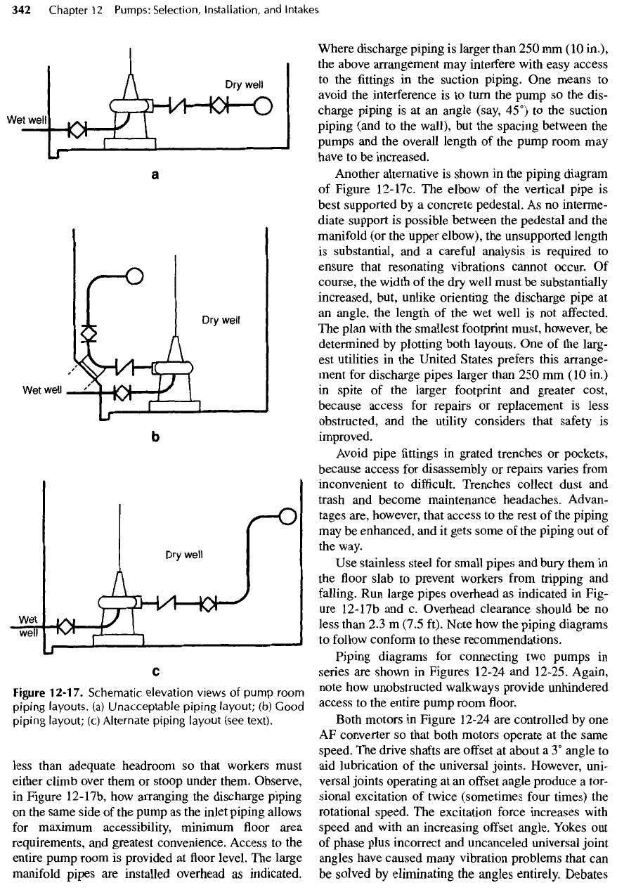
Figure
12-17.
Schematic
elevation
views
of
pump
room
piping
layouts,
(a)
Unacceptable
piping
layout;
(b)
Good
piping
layout;
(c)
Alternate
piping
layout
(see
text).
less than adequate headroom
so
that workers must
either climb over them
or
stoop under them. Observe,
in
Figure
12-17b,
how
arranging
the
discharge piping
on
the
same side
of the
pump
as the
inlet piping allows
for
maximum accessibility, minimum
floor
area
requirements,
and
greatest convenience. Access
to the
entire pump room
is
provided
at floor
level.
The
large
manifold
pipes
are
installed overhead
as
indicated.
Where discharge piping
is
larger than
250 mm (10
in.),
the
above arrangement
may
interfere with easy access
to
the fittings in the
suction
piping.
One
means
to
avoid
the
interference
is to
turn
the
pump
so the
dis-
charge piping
is at an
angle (say, 45°)
to the
suction
piping (and
to the
wall),
but the
spacing between
the
pumps
and the
overall length
of the
pump room
may
have
to be
increased.
Another alternative
is
shown
in the
piping diagram
of
Figure
12-17c.
The
elbow
of the
vertical pipe
is
best supported
by a
concrete pedestal.
As no
interme-
diate support
is
possible between
the
pedestal
and the
manifold
(or the
upper elbow),
the
unsupported length
is
substantial,
and a
careful
analysis
is
required
to
ensure that resonating vibrations cannot occur.
Of
course,
the
width
of the dry
well must
be
substantially
increased,
but, unlike
orienting
the
discharge
pipe
at
an
angle,
the
length
of the wet
well
is not
affected.
The
plan with
the
smallest footprint must, however,
be
determined
by
plotting both layouts.
One of the
larg-
est
utilities
in the
United States prefers this arrange-
ment
for
discharge
pipes
larger than
250 mm (10
in.)
in
spite
of the
larger
footprint
and
greater cost,
because
access
for
repairs
or
replacement
is
less
obstructed,
and the
utility considers that
safety
is
improved.
Avoid
pipe
fittings in
grated trenches
or
pockets,
because access
for
disassembly
or
repairs varies
from
inconvenient
to
difficult.
Trenches collect dust
and
trash
and
become maintenance headaches. Advan-
tages are, however, that access
to the
rest
of the
piping
may
be
enhanced,
and it
gets some
of the
piping
out of
the
way.
Use
stainless
steel
for
small
pipes
and
bury them
in
the floor
slab
to
prevent workers
from
tripping
and
falling.
Run
large pipes overhead
as
indicated
in
Fig-
ure
12-17b
and c.
Overhead clearance should
be no
less than
2.3
m
(7.5 ft). Note
how the
piping diagrams
to
follow
conform
to
these recommendations.
Piping diagrams
for
connecting
two
pumps
in
series
are
shown
in
Figures 12-24
and
12-25. Again,
note
how
unobstructed walkways provide unhindered
access
to the
entire pump room
floor.
Both
motors
in
Figure 12-24
are
controlled
by one
AF
converter
so
that both motors operate
at the
same
speed.
The
drive
shafts
are
offset
at
about
a
3°
angle
to
aid
lubrication
of the
universal joints. However, uni-
versal
joints
operating
at an
offset
angle produce
a
tor-
sional
excitation
of
twice (sometimes
four
times)
the
rotational speed.
The
excitation force increases with
speed
and
with
an
increasing
offset
angle. Yokes
out
of
phase plus incorrect
and
uncanceled universal joint
angles have caused many vibration
problems
that
can
be
solved
by
eliminating
the
angles entirely. Debates
about
the
need
for
offset
angles
led the
Spicer Com-
pany
to a
test
of two
shafts
—
one
at
zero
offset
and
one at a 3°
offset
angle. Both
failed
at
about
the
same
time.
An
offset
angle
of
true zero cannot
be
achieved
in
practice,
and the
unavoidable tiny angle
is
sufficient
to
distribute grease
to the
needle bearings
and to
pre-
vent
"brinelling."
Strong opinions
pro and con
still
persist,
but if the
manufacturer prescribes
offsetting
the
shaft,
use the
smallest angle acceptable.
Drive
shafts
operating between
offset
universal
joints accelerate
and
decelerate twice
per
revolution.
If
the
angles
at
each
end are
different,
the
shaft
tries
to
accelerate
at two
different
rates.
If the
yokes
are not in
the
same plane,
the
shaft
tries
to
start
and
stop acceler-
ating
at
different
times, thereby causing torsional
and
bending stresses
in the
shaft
and
vibration
in the
drive
train.
The
worst situation
is
offsetting
two
drive
shafts
between
a
coaxial pump
and
motor.
If
upper
and
lower
offset
angles
are 3°, the
central angle
is 6°, and the
shaft
bends
in an "S"
shape.
The
center universal
joints will have
a
short life.
The
pump
and
driver train
in
Figure 12-25
is
unusually
long because
of the flywheel
located
between
the
motor
and the
pump
on the right. The use
of
a
single motor
for
both pumps ensures that both
operate
at the
same speed.
Equipment
Supports
Rotating equipment
is
best supported
on
massive
concrete structures. Regardless, concrete
and
steel
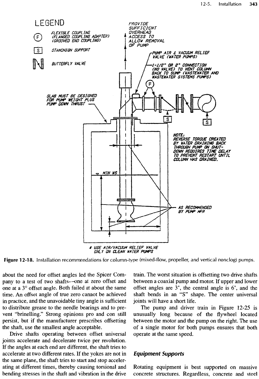
Figure
12-18.
Installation
recommendations
for
column-type
(mixed-flow,
propeller,
and
vertical
nonclog)
pumps.
