Pumping Station Desing - Second Edition by Robert L. Sanks, George Tchobahoglous, Garr M. Jones
Подождите немного. Документ загружается.

Discharge
case
and
adapter.
The
discharge case
(Figure
11-24)
or
discharge adapter
is
mounted
on
the top
bowl. Both
of
them
contain
the
threaded
or
bolted connection
for
attachment
of the
bowl
assembly
to the
column.
The
discharge case con-
tains
a
center
hub to
which
the
enclosing tube
can
be
connected.
The
discharge adapter
is
fully
open
on
the
inside
and
does
not
accept
an
enclosing tube.
Column
and
Lineshafting
The
column supports
the
bowl assembly, ducts
the
liq-
uid
to the
discharge head,
and
encloses
the
lineshaft-
ing. Column pipe
is
available with threaded
or
flanged
connections (Figure
11-27).
The
threaded column
has
a
smaller outside
diameter,
which
is
important
in
well
installations.
The
flanged
column
is
easier
to
assemble
and
disassemble.
The
lineshafting transmits
the
torque
from
the
driver
to the
pump rotor.
The
lineshafting sections
are
connected
to
each other with threaded couplings
or,
for
larger diameter
shafts,
with sleeve couplings.
Open lineshafting
is
exposed
to the
pumped liquid
and
is
guided
in
lineshaft bearings, which
are
sup-
ported
in
bearing retainers. Lineshaft sleeves protect
the
shafting
from
wear
in the
bearings. With
the
enclosed lineshafting (Figure
ll-27b),
the
enclosing
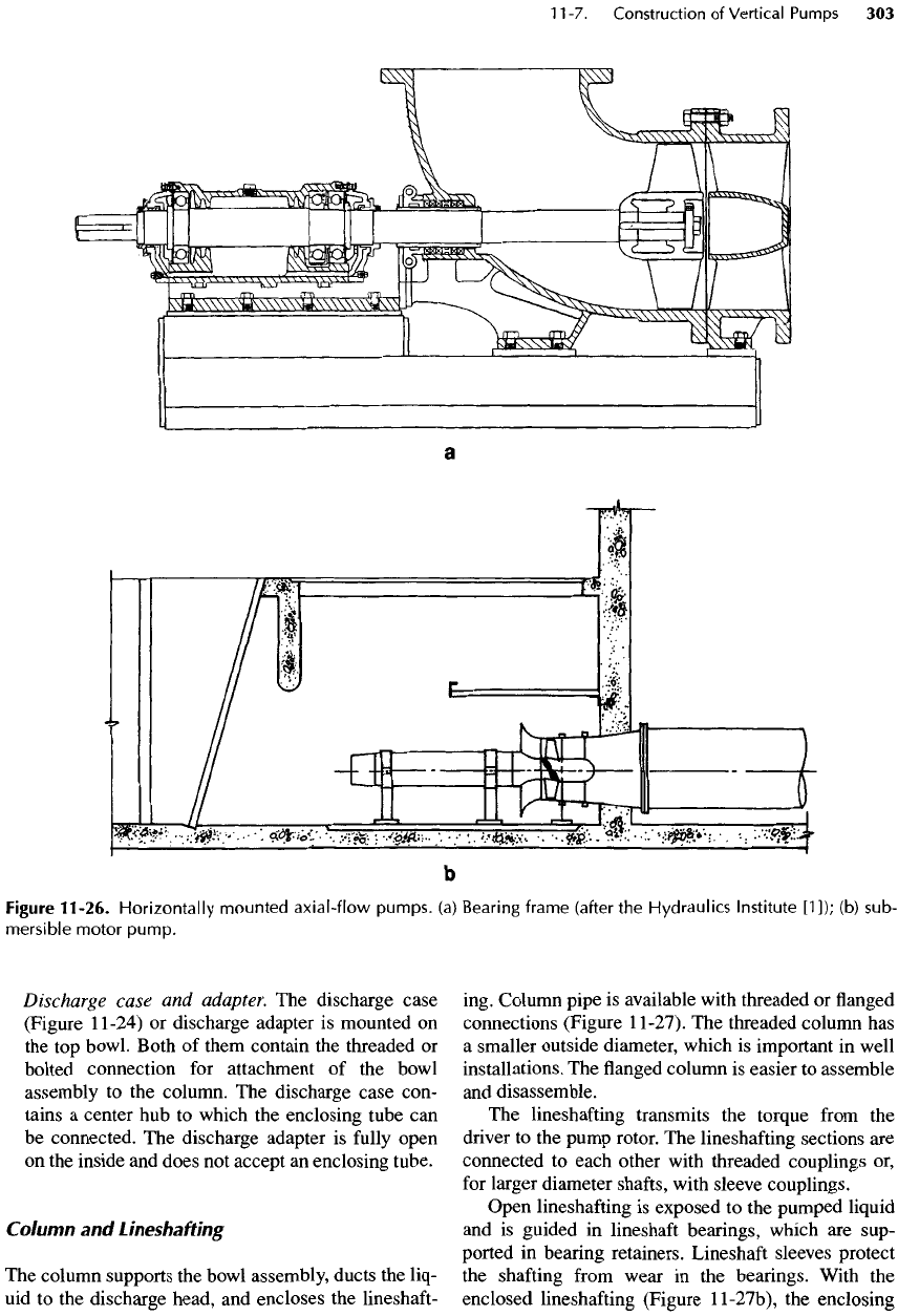
Figure
11-26.
Horizontally
mounted
axial-flow
pumps,
(a)
Bearing frame (after
the
Hydraulics Institute
[1]);
(b)
sub-
mersible
motor
pump.
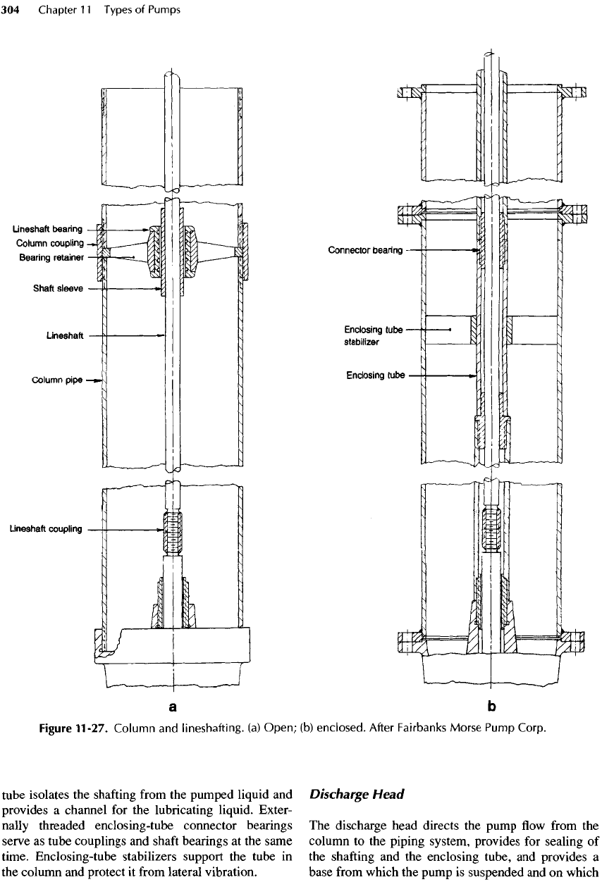
tube
isolates
the
shafting
from
the
pumped liquid
and
provides
a
channel
for the
lubricating liquid. Exter-
nally
threaded enclosing-tube connector bearings
serve
as
tube couplings
and
shaft
bearings
at the
same
time.
Enclosing-tube stabilizers support
the
tube
in
the
column
and
protect
it
from
lateral vibration.
Discharge
Head
The
discharge head directs
the
pump
flow
from
the
column
to the
piping system, provides
for
sealing
of
the
shafting
and the
enclosing tube,
and
provides
a
base
from
which
the
pump
is
suspended
and on
which
Figure
11-27.
Column
and
lineshafting.
(a)
Open;
(b)
enclosed.
After Fairbanks
Morse
Pump
Corp.
the
driver
is
mounted (Figure
11-24).
The
discharge
head
may be a
casting
or a
fabricated component.
The
discharge head
usually
contains
a
separate
packing
box
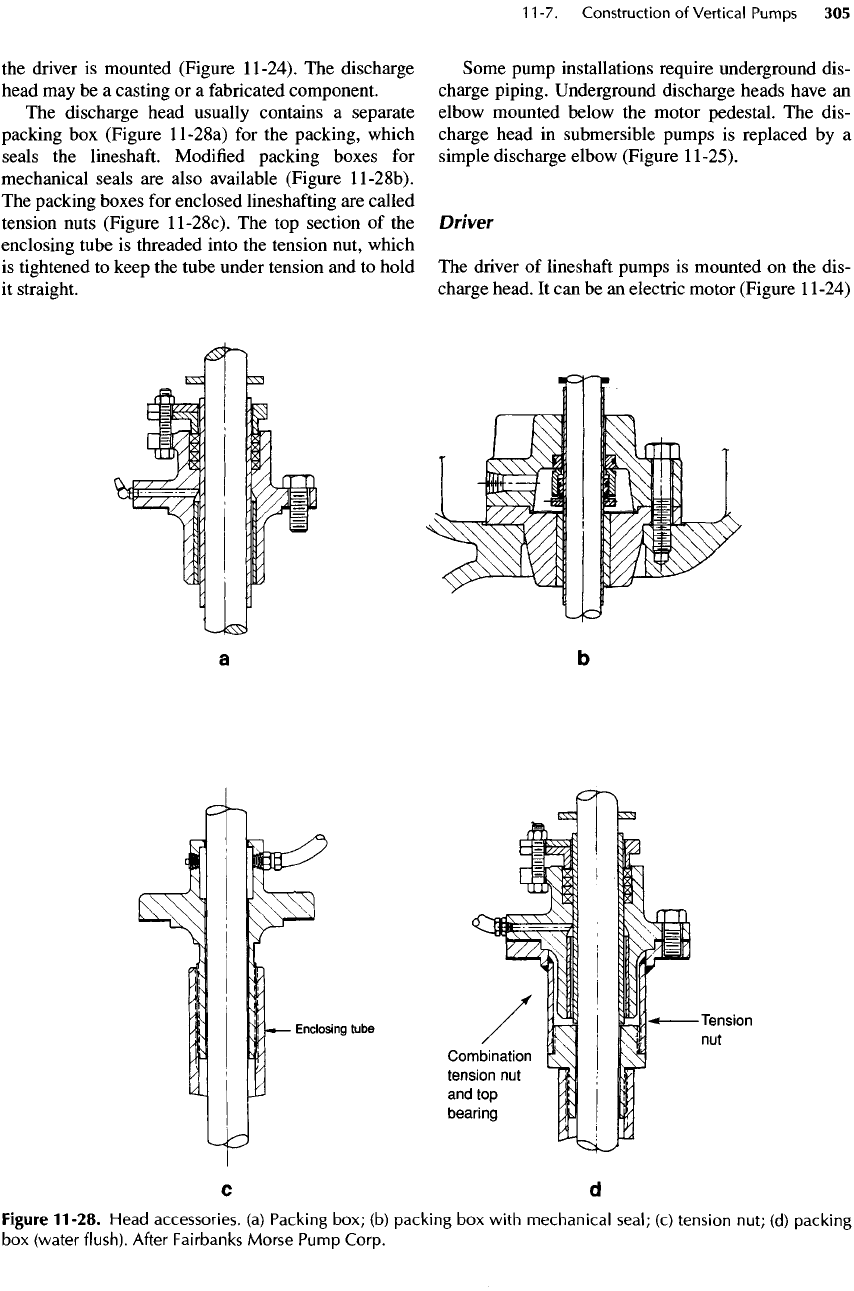
(Figure
ll-28a)
for the
packing, which
seals
the
lineshaft.
Modified
packing boxes
for
mechanical
seals
are
also available (Figure
ll-28b).
The
packing boxes
for
enclosed lineshafting
are
called
tension nuts (Figure
ll-28c).
The top
section
of the
enclosing tube
is
threaded into
the
tension nut, which
is
tightened
to
keep
the
tube under tension
and to
hold
it
straight.
Some pump installations require underground dis-
charge piping. Underground discharge heads have
an
elbow mounted below
the
motor pedestal.
The
dis-
charge head
in
submersible pumps
is
replaced
by a
simple discharge elbow (Figure
11-25).
Driver
The
driver
of
lineshaft pumps
is
mounted
on the
dis-
charge head.
It can be an
electric
motor (Figure
1
1-24)
Figure
11-28.
Head
accessories,
(a)
Packing
box;
(b)
packing
box
with
mechanical
seal;
(c)
tension
nut;
(d)
packing
box
(water
flush).
After
Fairbanks
Morse
Pump
Corp.
or an
angle gear with
an
engine. Because
the
pump
bowl
assembly
or
column contains
no
thrust bearings,
the
driver must
be
equipped with
a
thrust bearing
capable
of
supporting
the
hydraulic axial thrust
of the
pump
and the
weight
of the
pump rotor with
its
line-
shaft.
Solid
shaft
drivers require
an
axially adjustable
coupling
for the top
section
of the
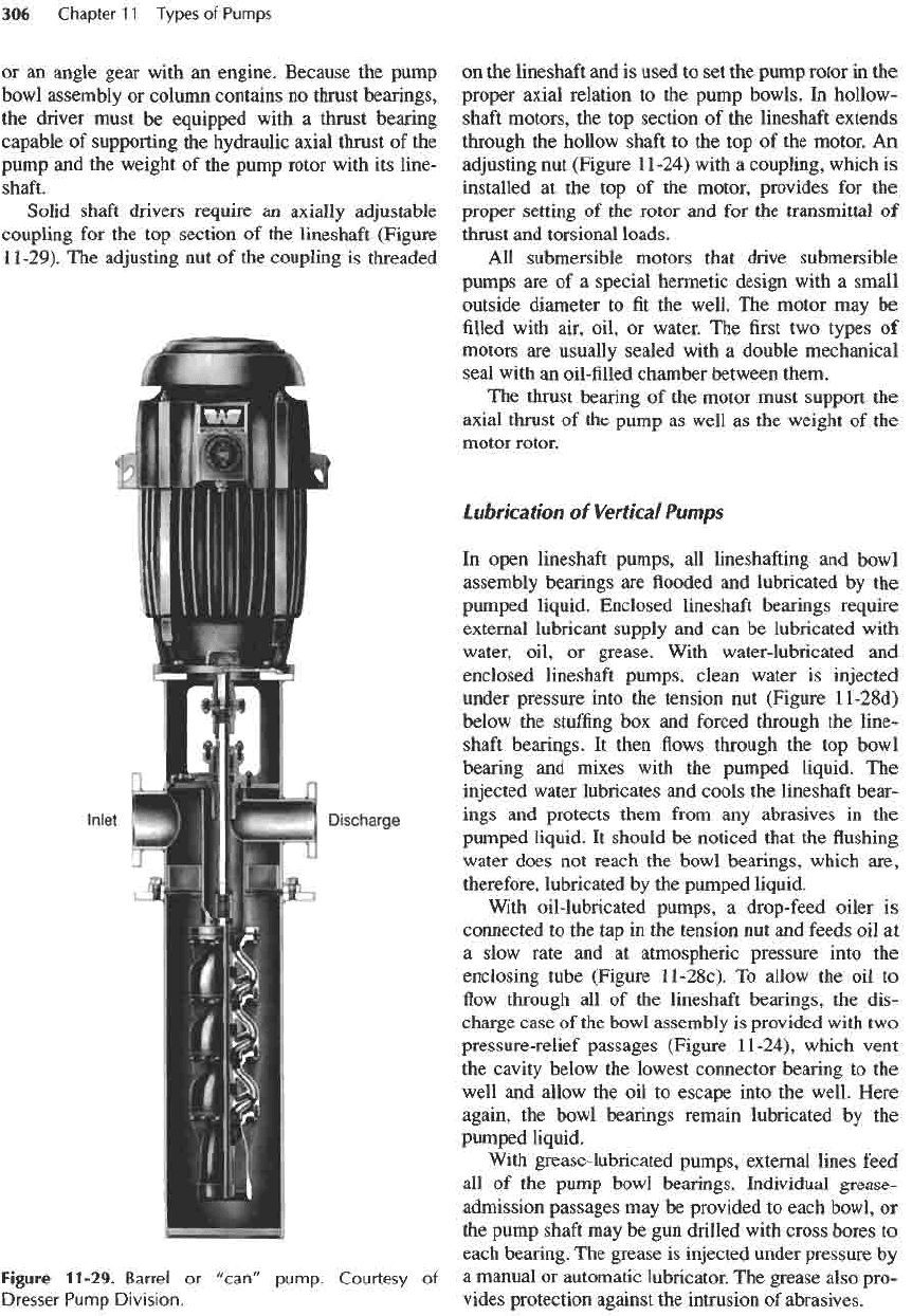
lineshaft (Figure
11-29).
The
adjusting
nut of the
coupling
is
threaded
Figure
11-29.
Barrel
or
"can"
pump.
Courtesy
of
Dresser
Pump
Division.
on
the
lineshaft
and is
used
to set the
pump rotor
in the
proper axial relation
to the
pump bowls.
In
hollow-
shaft
motors,
the top
section
of the
lineshaft extends
through
the
hollow
shaft
to the top of the
motor.
An
adjusting
nut
(Figure
1
1-24)
with
a
coupling, which
is
installed
at the top of the
motor, provides
for the
proper
setting
of the
rotor
and for the
transmittal
of
thrust
and
torsional
loads.
All
submersible motors that drive submersible
pumps
are of a
special
hermetic design with
a
small
outside diameter
to fit the
well.
The
motor
may be
filled
with
air, oil,
or
water.
The first two
types
of
motors
are
usually sealed with
a
double mechanical
seal with
an
oil-filled chamber between them.
The
thrust bearing
of the
motor must support
the
axial thrust
of the
pump
as
well
as the
weight
of the
motor rotor.
Lubrication
of
Vertical
Pumps
In
open lineshaft pumps,
all
lineshafting
and
bowl
assembly bearings
are flooded and
lubricated
by the
pumped liquid. Enclosed lineshaft bearings require
external lubricant supply
and can be
lubricated with
water, oil,
or
grease. With water-lubricated
and
enclosed lineshaft pumps, clean water
is
injected
under pressure into
the
tension
nut
(Figure
ll-28d)
below
the
stuffing
box and
forced through
the
line-
shaft
bearings.
It
then
flows
through
the top
bowl
bearing
and
mixes with
the
pumped liquid.
The
injected
water lubricates
and
cools
the
lineshaft bear-
ings
and
protects
them
from
any
abrasives
in the
pumped liquid.
It
should
be
noticed that
the flushing
water does
not
reach
the
bowl bearings, which are,
therefore, lubricated
by the
pumped liquid.
With oil-lubricated pumps,
a
drop-feed oiler
is
connected
to the tap in the
tension
nut and
feeds
oil at
a
slow rate
and at
atmospheric pressure into
the
enclosing tube (Figure
ll-28c).
To
allow
the oil to
flow
through
all of the
lineshaft bearings,
the
dis-
charge case
of the
bowl assembly
is
provided with
two
pressure-relief passages (Figure
11-24),
which vent
the
cavity below
the
lowest connector bearing
to the
well
and
allow
the oil to
escape into
the
well. Here
again,
the
bowl bearings remain lubricated
by the
pumped liquid.
With
grease-lubricated pumps, external lines feed
all of the
pump bowl bearings. Individual grease-
admission passages
may be
provided
to
each bowl,
or
the
pump
shaft
may be gun
drilled with cross bores
to
each
bearing.
The
grease
is
injected under
pressure
by
a
manual
or
automatic lubricator.
The
grease also pro-
vides protection against
the
intrusion
of
abrasives.
1 1
-8.
Types
of
Vertical Pumps
The
types
of
vertical pumps
are
shown
in
Figure
11-lb.
Deep
Well,
Lineshaft
Pumps
A
typical
lineshaft-driven
deep well pump
is
shown
in
Figure
11-24.
The
bowl assembly
of the
pump
may
contain
as
many
as 60
stages, depending
on the
well
setting
and on the
discharge pressure requirements.
The
bowls
may be
equipped with enclosed
or
semi-open
impellers
and
optional wear
rings or
wear plates. Semi-
open impellers
offer
the
advantage
of
end-clearance
adjustability
for
pumping liquids with
a
higher abrasive
content,
but
they
are
difficult
to
adjust
for
deep settings.
Lineshafting.
The
lineshafting
is
usually open
for
settings
up to 75 m
(250
ft) and is
usually enclosed
for
deeper settings. Enclosed
shafting
is
drip
fed
and
lubricated with oil. Open
shafting
is
lubricated
with
pumpage
but
requires prelubrication with
water
before starting, because
the
lineshaft bearings
must
be
provided with lubricant
to
avoid
dry
run-
ning
until they become
flooded
with
the
pumped
liquid. Grease lubrication
is not
very practical
due
to the
requirement
for
long grease lines.
Column
and
head.
The
column
and the
head must
be
designed
for the
anticipated pressure
and for
high
axial loads.
For
column diameters
up to 300
mm
(12
in.),
columns
are
usually threaded. Larger
columns
are
usually
flanged
for
ease
of
assembly
and
disassembly.
Axial
Thrust
The
thrust
due to the
total dynamic head (including
the
pumped liquid contained
in the
column) combined
with
the
weight
of the
bowl assembly,
the
lineshaft,
and the
column causes significant stretching
of
both
the
lineshaft
and the
column. This must
be
considered
in
component selection.
The
column
and the
lineshaft
stretch
by
different
amounts,
and the final
axial setting
of
the
rotor requires particular attention with deep
well
pumps.
Deep
Well
Submersible
Pumps
Submersible motor-driven pumps (Figure
11-25)
are
another
popular
configuration
of
deep well pumps. They
have
no
lineshafting and, therefore,
no
related problems.
The
overall
efficiency
is
improved somewhat because
there
are no
lineshafting
friction
losses. These advan-
tages become greater
as the
well depth increases.
On the
other hand, they must
be
equipped with
a
special sub-
mersible motor
and a
long power-supply cable.
The
motor
is not
accessible
for
inspection
or
maintenance
without
pulling
the
entire pump
from the
well (see Table
25-8).
The
reliability
and
life
of a
submersible pump
depend greatly
on the
motor design
and
quality.
All
bowl
and
column components
of
submersible
pumps
are
very similar
to
those
of
lineshaft pumps.
Discharge
Elbow
The
discharge elbow (Figure
11-25)
replaces
the
dis-
charge head
of
lineshaft pumps.
It is
rather simple
in
design
but
must
be
capable
of
supporting
the
bowl
assembly with
the
motor
and the
column.
Lubrication
The
pump bearings
are
lubricated with pumpage
because there
is no
practical
way to
supply lubricants
of
any
kind
from
an
outside source.
The
motor bear-
ings
are
sealed
in the
motor and, depending
on the
motor design,
are
lubricated with water
or
oil.
The
hydraulic axial thrust
and the
weight
of the
pump
and
the
motor rotor
are
carried
by the
motor thrust bearing.
Short-Setting
Lineshaft
Pumps
The
basic components
of a
short-setting pump
are the
same
as
those
of a
deep well pump.
The
major
differ-
ence
is in the
length
of the
column
and in the
light-
weight
design
of the
column
and the
head.
The
column
of a
short-setting pump
is
often
limited
to one
section; occasionally,
it is
eliminated altogether with
the
bowl mounted
to the
head directly.
Bowl assembly.
The
bowl assemblies
are
one-
or
two-stage propeller bowls (Figure
11-30)
or
single-
and
multistage
mixed-flow
bowls.
Lineshafting
and
options.
The
lineshafting
can be
open
or
enclosed.
The
lineshafting
and
bowl assem-
bly
can be
lubricated with pumpage, water
flush,
oil,
or
grease.
The
wear ring
or
wear plate, packing
or
mechanical seal,
and
different
bearing material
options
are
available
and are of
greater importance,
because short-setting pumps
are
used
to
pump
a
great variety
of
liquids.
Installation.
Short-setting pumps usually take their
suction
from
a wet
well.
The
performance
of
vertical
pumps
is
rather sensitive
to
inlet
flow
conditions.
The wet
well should, therefore,
be
designed
by a
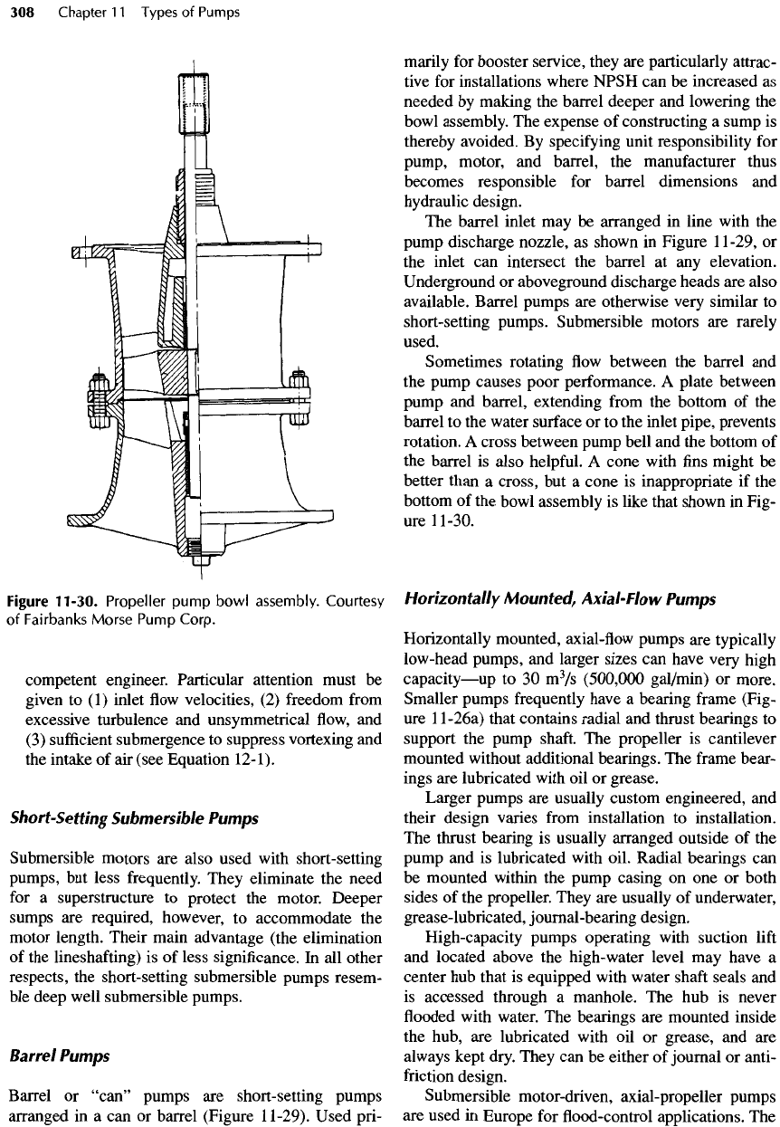
Figure
11-30.
Propeller
pump
bowl
assembly.
Courtesy
of
Fairbanks
Morse
Pump
Corp.
competent
engineer. Particular attention
must
be
given
to (1)
inlet
flow
velocities,
(2)
freedom
from
excessive turbulence
and
unsymmetrical
flow, and
(3)
sufficient
submergence
to
suppress
vortexing
and
the
intake
of air
(see Equation
12-1).
Short-Setting
Submersible
Pumps
Submersible motors
are
also used with short-setting
pumps,
but
less frequently. They eliminate
the
need
for
a
superstructure
to
protect
the
motor.
Deeper
sumps
are
required, however,
to
accommodate
the
motor length. Their main advantage (the elimination
of
the
lineshafting)
is of
less significance.
In all
other
respects,
the
short-
setting
submersible pumps resem-
ble
deep well submersible pumps.
Barrel
Pumps
Barrel
or
"can"
pumps
are
short-setting pumps
arranged
in a can or
barrel (Figure
11-29).
Used pri-
marily
for
booster service, they
are
particularly attrac-
tive
for
installations where NPSH
can be
increased
as
needed
by
making
the
barrel deeper
and
lowering
the
bowl
assembly.
The
expense
of
constructing
a
sump
is
thereby avoided.
By
specifying unit responsibility
for
pump,
motor,
and
barrel,
the
manufacturer thus
becomes responsible
for
barrel dimensions
and
hydraulic design.
The
barrel inlet
may be
arranged
in
line with
the
pump
discharge nozzle,
as
shown
in
Figure
11-29,
or
the
inlet
can
intersect
the
barrel
at any
elevation.
Underground
or
aboveground discharge heads
are
also
available. Barrel pumps
are
otherwise very similar
to
short-setting
pumps.
Submersible motors
are
rarely
used.
Sometimes rotating
flow
between
the
barrel
and
the
pump causes poor performance.
A
plate between
pump
and
barrel, extending
from
the
bottom
of the
barrel
to the
water surface
or to the
inlet pipe, prevents
rotation.
A
cross between pump bell
and the
bottom
of
the
barrel
is
also
helpful.
A
cone with
fins
might
be
better
than
a
cross,
but a
cone
is
inappropriate
if the
bottom
of the
bowl assembly
is
like that shown
in
Fig-
ure
11-30.
Horizontally
Mounted,
Axial-Flow
Pumps
Horizontally mounted,
axial-flow
pumps
are
typically
low-head
pumps,
and
larger sizes
can
have very high
capacity
—
up
to 30
m
3
/s
(500,000
gal/min)
or
more.
Smaller pumps frequently have
a
bearing
frame
(Fig-
ure
ll-26a)
that contains radial
and
thrust bearings
to
support
the
pump
shaft.
The
propeller
is
cantilever
mounted without additional bearings.
The
frame
bear-
ings
are
lubricated with
oil or
grease.
Larger pumps
are
usually custom engineered,
and
their design varies
from
installation
to
installation.
The
thrust bearing
is
usually arranged outside
of the
pump
and is
lubricated with oil. Radial bearings
can
be
mounted within
the
pump casing
on one or
both
sides
of the
propeller. They
are
usually
of
underwater,
grease-lubricated, journal-bearing design.
High-capacity pumps operating with suction
lift
and
located above
the
high-water level
may
have
a
center
hub
that
is
equipped with water
shaft
seals
and
is
accessed through
a
manhole.
The hub is
never
flooded
with
water.
The
bearings
are
mounted inside
the
hub,
are
lubricated with
oil or
grease,
and are
always
kept dry. They
can be
either
of
journal
or
anti-
friction
design.
Submersible motor-driven, axial-propeller pumps
are
used
in
Europe
for flood-control
applications.
The
motor
of
these pumps
may be filled
with water
and the
bearings lubricated with water.
The
pump
and
motor
are
inherently
flood
resistant. Such pumping stations
are
compact,
low in
cost,
and
require
no
pump house.
Only
the
controls
and the
power supply
are
installed
above
the
surface
(Figure
ll-26b).
Submerged hydraulic motor-driven, axial-propel-
ler,
and
mixed-flow
pumps
are
also available.
In
these
units
the
hydraulic
fluid
power unit
is
electric motor
or
engine driven
and
located away
from
the
pump.
The
only connection
to the
pump
is a
pair
of
hydraulic
hoses.
11-9.
Positive-Displacement
Pumps
When compared with kinetic pumps, positive-dis-
placement pumps
are
inherently low-capacity, high-
discharge-pressure pumps. Although they
are
used
to
pump
a
great variety
of
liquids, they
are
also capable
of
pumping slurries
in
small volumes
or in
consisten-
cies that cannot
be
handled
by
centrifugal
pumps
—
the
basic reason
for
using positive-displacement pumps
in
water
and
wastewater pumping
and
treatment stations.
Only
designs suitable
for
sewage, slurries, sludge,
and
similar liquids
are
discussed
in
this chapter.
As
shown
in
Figure
11
-Ic,
positive-displacement
pumps
are
subdivided into three
categories:
recipro-
cating pumps, rotary pumps,
and
pneumatic (ejector)
pumps.
Of all the
various reciprocating pumps, only
the
plunger pump
is of
interest
for
pumping sludge
and
slurries.
Two
types
of
rotary pumps
are of
inter-
est: lobe pumps
and
progressive cavity pumps.
The
only type
of
pneumatic positive-displacement
pump
of
interest
is the
pneumatic ejector.
It is
used
for
pumping
raw
sewage
in
small volumes and, some-
times, high heads.
Plunger
Pumps
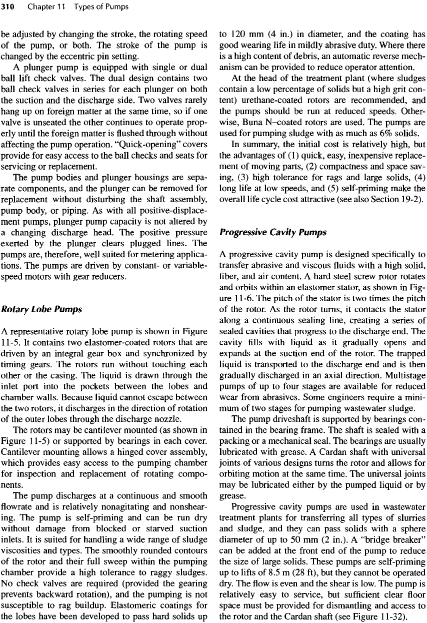
A
representative plunger pump
is
shown
in
Figure
11-31.
It can be
used
for all
types
of
sewage, sludge,
scum, slurries,
and
clarifier
and
thickener
underflow.
It
can be
applied
for
transfer
and for
metering service.
Such pumps
are
available
in
single-
and
multicylinder
models.
The
plunger contains
the
crosshead, driven
by
a
camshaft
arrangement.
The
capacity
of the
pump
can
Figure
11-31.
A
plunger
pump.
Courtesy
of
Komline-Sanderson
Engineering
Corp.
be
adjusted
by
changing
the
stroke,
the
rotating speed
of
the
pump,
or
both.
The
stroke
of the
pump
is
changed
by the
eccentric
pin
setting.
A
plunger pump
is
equipped with single
or
dual
ball
lift
check valves.
The
dual design contains
two
ball check valves
in
series
for
each plunger
on
both
the
suction
and the
discharge
side.
Two
valves rarely
hang
up on
foreign matter
at the
same time,
so if one
valve
is
unseated
the
other continues
to
operate prop-
erly until
the
foreign matter
is
flushed
through without
affecting
the
pump
operation.
"Quick-opening"
covers
provide
for
easy access
to the
ball checks
and
seats
for
servicing
or
replacement.
The
pump bodies
and
plunger housings
are
sepa-
rate components,
and the
plunger
can be
removed
for
replacement without disturbing
the
shaft
assembly,
pump
body,
or
piping.
As
with
all
positive-displace-
ment pumps, plunger pump capacity
is not
altered
by
a
changing discharge head.
The
positive pressure
exerted
by the
plunger clears plugged lines.
The
pumps
are, therefore, well suited
for
metering applica-
tions.
The
pumps
are
driven
by
constant-
or
variable-
speed motors
with
gear reducers.
Rotary
Lobe
Pumps
A
representative rotary lobe pump
is
shown
in
Figure
11-5.
It
contains
two
elastomer-coated rotors that
are
driven
by an
integral
gear
box and
synchronized
by
timing
gears.
The
rotors
run
without touching each
other
or the
casing.
The
liquid
is
drawn through
the
inlet port into
the
pockets between
the
lobes
and
chamber walls. Because liquid cannot escape between
the two
rotors,
it
discharges
in the
direction
of
rotation
of
the
outer lobes through
the
discharge nozzle.
The
rotors
may be
cantilever mounted
(as
shown
in
Figure
11-5)
or
supported
by
bearings
in
each cover.
Cantilever mounting allows
a
hinged cover assembly,
which
provides easy access
to the
pumping chamber
for
inspection
and
replacement
of
rotating compo-
nents.
The
pump discharges
at a
continuous
and
smooth
flowrate
and
is
relatively nonagitating
and
nonshear-
ing.
The
pump
is
self-priming
and can be run dry
without
damage
from
blocked
or
starved suction
inlets.
It is
suited
for
handling
a
wide range
of
sludge
viscosities
and
types.
The
smoothly rounded contours
of
the
rotor
and
their
full
sweep within
the
pumping
chamber provide
a
high tolerance
to
raggy sludges.
No
check valves
are
required (provided
the
gearing
prevents backward rotation),
and the
pumping
is not
susceptible
to rag
buildup. Elastomeric coatings
for
the
lobes have been developed
to
pass hard solids
up
to 120 mm (4
in.)
in
diameter,
and the
coating
has
good wearing
life
in
mildly abrasive duty. Where there
is
a
high content
of
debris,
an
automatic reverse mech-
anism
can be
provided
to
reduce
operator
attention.
At
the
head
of the
treatment plant (where sludges
contain
a low
percentage
of
solids
but a
high grit con-
tent) urethane-coated rotors
are
recommended,
and
the
pumps should
be run at
reduced speeds. Other-
wise, Buna
N-coated
rotors
are
used.
The
pumps
are
used
for
pumping sludge with
as
much
as 6%
solids.
In
summary,
the
initial
cost
is
relatively high,
but
the
advantages
of (1)
quick, easy, inexpensive replace-
ment
of
moving parts,
(2)
compactness
and
space sav-
ing,
(3)
high tolerance
for
rags
and
large
solids,
(4)
long
life
at low
speeds,
and (5)
self-priming make
the
overall
life
cycle cost attractive (see also Section 19-2).
Progressive
Cavity
Pumps
A
progressive cavity pump
is
designed
specifically
to
transfer
abrasive
and
viscous
fluids
with
a
high solid,
fiber,
and
air
content.
A
hard steel screw rotor rotates
and
orbits within
an
elastomer stator,
as
shown
in
Fig-
ure
11-6.
The
pitch
of the
stator
is two
times
the
pitch
of
the
rotor.
As the
rotor turns,
it
contacts
the
stator
along
a
continuous sealing line, creating
a
series
of
sealed cavities that progress
to the
discharge end.
The
cavity
fills
with liquid
as it
gradually opens
and
expands
at the
suction
end of the
rotor.
The
trapped
liquid
is
transported
to the
discharge
end and is
then
gradually
discharged
in an
axial direction. Multistage
pumps
of up to
four
stages
are
available
for
reduced
wear
from
abrasives. Some engineers require
a
mini-
mum
of two
stages
for
pumping wastewater sludge.
The
pump
driveshaft
is
supported
by
bearings con-
tained
in the
bearing
frame.
The
shaft
is
sealed with
a
packing
or a
mechanical seal.
The
bearings
are
usually
lubricated with
grease.
A
Cardan
shaft
with universal
joints
of
various designs turns
the
rotor
and
allows
for
orbiting motion
at the
same time.
The
universal joints
may
be
lubricated either
by the
pumped liquid
or by
grease.
Progressive cavity pumps
are
used
in
wastewater
treatment plants
for
transferring
all
types
of
slurries
and
sludge,
and
they
can
pass solids with
a
sphere
diameter
of up to 50 mm (2
in.).
A
"bridge
breaker"
can be
added
at the
front
end of the
pump
to
reduce
the
size
of
large solids. These pumps
are
self-priming
up to
lifts
of 8.5 m (28
ft),
but
they cannot
be
operated
dry.
The flow is
even
and the
shear
is
low.
The
pump
is
relatively easy
to
service,
but
sufficient
clear
floor
space must
be
provided
for
dismantling
and
access
to
the
rotor
and the
Cardan
shaft
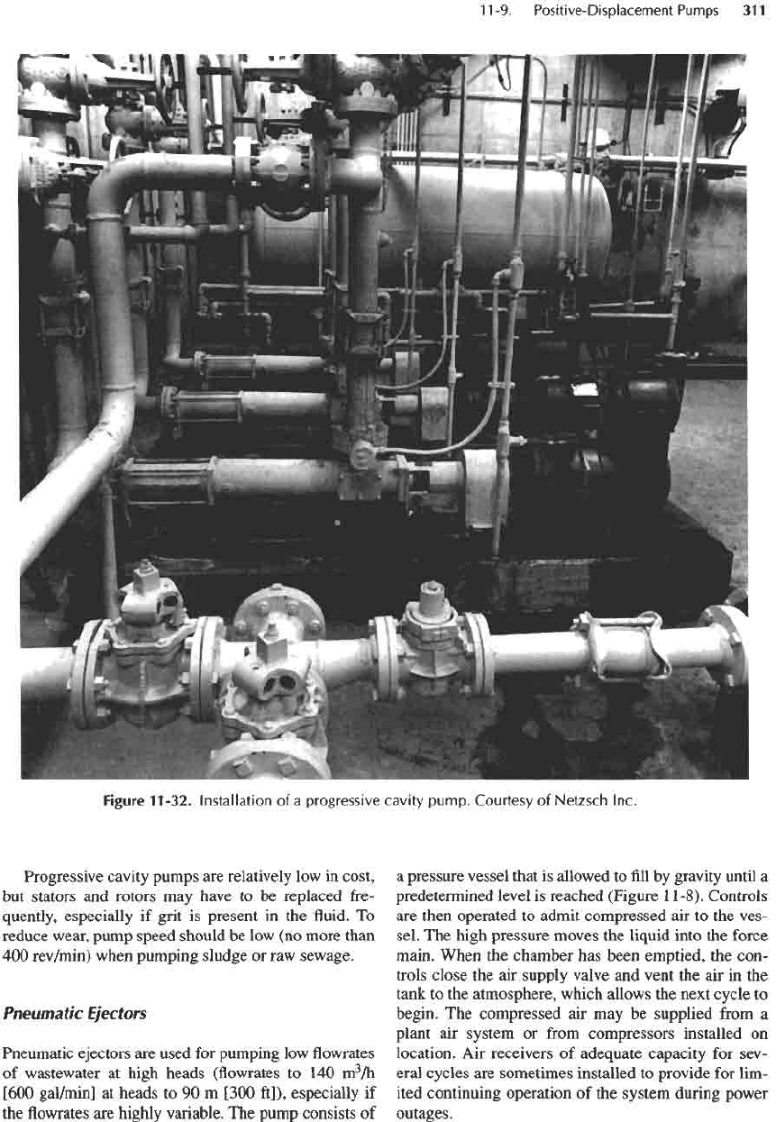
(see Figure
1
1-32).
Progressive cavity pumps
are
relatively
low in
cost,
but
stators
and
rotors
may
have
to be
replaced fre-
quently,
especially
if
grit
is
present
in the fluid. To
reduce wear, pump speed should
be low (no
more than
400
rev/min)
when pumping sludge
or raw
sewage.
Pneumatic
Ejectors
Pneumatic
ejectors
are
used
for
pumping
low flowrates
of
wastewater
at
high heads
(flowrates
to 140
m
3
/h
[600
gal/min]
at
heads
to 90
m
[300
ft]),
especially
if
the flowrates are
highly variable.
The
pump consists
of
a
pressure vessel that
is
allowed
to fill by
gravity until
a
predetermined level
is
reached (Figure
11-8).
Controls
are
then operated
to
admit compressed
air to the
ves-
sel.
The
high pressure moves
the
liquid into
the
force
main. When
the
chamber
has
been emptied,
the
con-
trols close
the air
supply valve
and
vent
the air in the
tank
to the
atmosphere, which allows
the
next cycle
to
begin.
The
compressed
air may be
supplied
from
a
plant
air
system
or
from
compressors installed
on
location.
Air
receivers
of
adequate capacity
for
sev-
eral cycles
are
sometimes installed
to
provide
for
lim-
ited continuing operation
of the
system during power
outages.
Figure
11-32.
Installation
of a
progressive cavity
pump.
Courtesy
of
Netzsch Inc.
Mechanical controls
for the
system have proven
to
be
more durable than electronic controls.
The
check
valves
should
be
specifically designed
for
passing sol-
ids and
stringy material. Because
of the
danger
of
freez-
ing,
the
pneumatic ejector
and the air
supply system
should
not be
exposed
to low
ambient temperatures.
11-10.
Special
Pumps
The
pumps
in
this section
are for the
limited purpose
of
producing either high pressures
at low flowrates or
moderate
to
large
flowrates
at low
lifts.
Regenerative
Turbine
Pumps
Regenerative turbine pumps derive their name
from
the
many buckets machined into
the
periphery
of the
impeller.
They have long been recognized
for
effi-
ciently producing
low flows at
pressures much higher
than
those
of
centrifugal pumps
of
comparable size.
They
are
excellent
for
seal water
and
washwater
pumps.
Regenerative turbine pumps
are
unique
in
opera-
tion.
The
liquid circulates
in and out of the
impeller
buckets many times
on its way
from
the
inlet
to the
outlet
of the
pump. Both centrifugal
and
shearing
action combine
to
impart additional energy
to the
liq-
uid
each time
it
passes through
the
buckets. Pressure
from
the
inlet
in
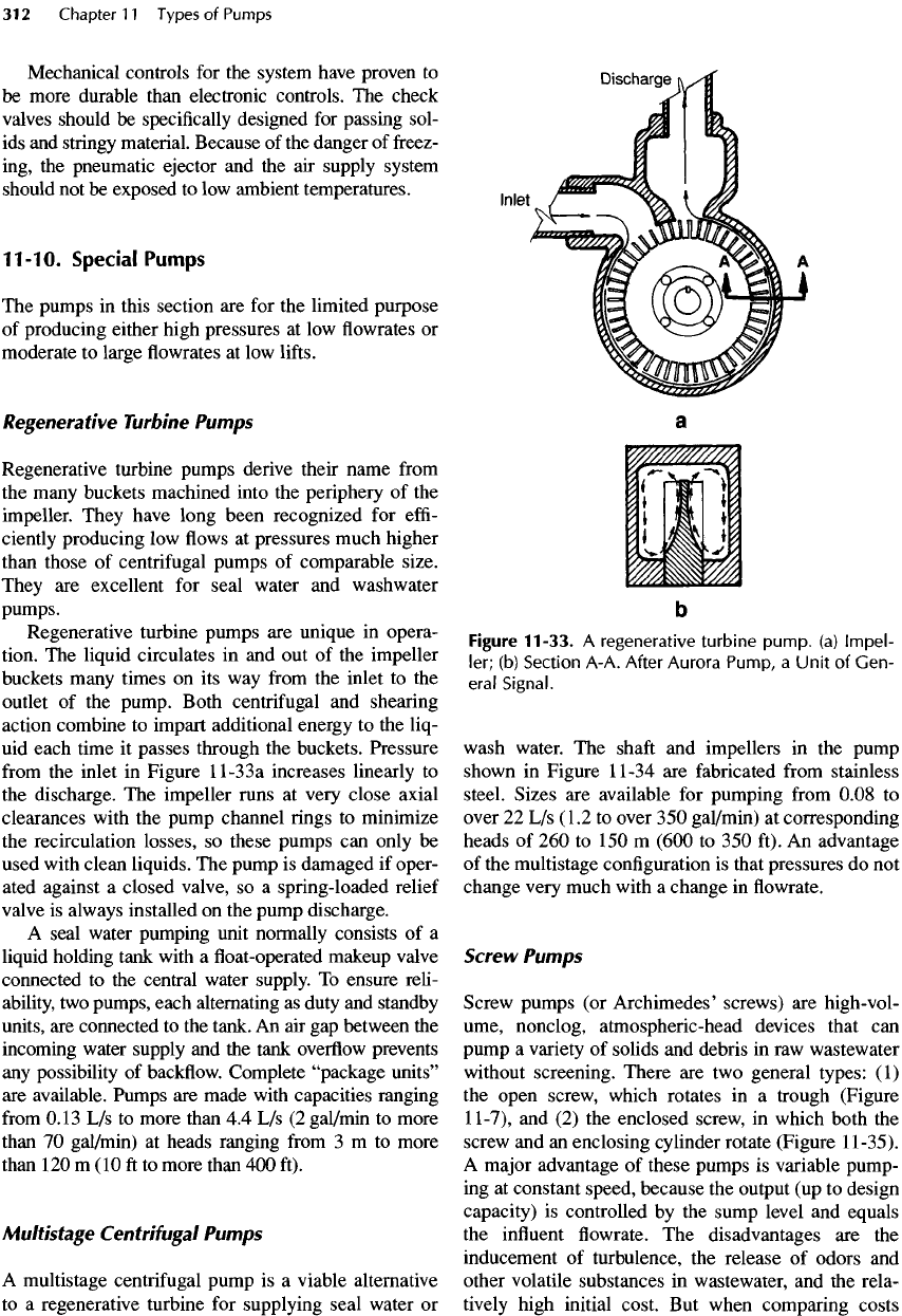
Figure
11
-3
3
a
increases
linearly
to
the
discharge.
The
impeller runs
at
very close axial
clearances with
the
pump channel
rings to
minimize
the
recirculation
losses,
so
these pumps
can
only
be
used with clean liquids.
The
pump
is
damaged
if
oper-
ated against
a
closed valve,
so a
spring-loaded relief
valve
is
always installed
on the
pump discharge.
A
seal water pumping unit normally consists
of a
liquid holding tank with
a float-operated
makeup valve
connected
to the
central water supply.
To
ensure reli-
ability,
two
pumps, each alternating
as
duty
and
standby
units,
are
connected
to the
tank.
An air gap
between
the
incoming water supply
and the
tank
overflow
prevents
any
possibility
of
backflow.
Complete
"package
units"
are
available. Pumps
are
made with capacities ranging
from
0.13
L/s to
more than
4.4 L/s (2
gal/min
to
more
than
70
gal/min)
at
heads ranging
from
3 m to
more
than
120
m (10 ft to
more than
400
ft).
Multistage
Centrifugal
Pumps
A
multistage centrifugal pump
is a
viable alternative
to a
regenerative turbine
for
supplying seal water
or
Figure
11-33.
A
regenerative
turbine
pump,
(a)
Impel-
ler;
(b)
Section
A-A.
After
Aurora
Pump,
a
Unit
of
Gen-
eral
Signal.
wash
water.
The
shaft
and
impellers
in the
pump
shown
in
Figure
11-34
are
fabricated
from
stainless
steel.
Sizes
are
available
for
pumping
from
0.08
to
over
22 L/s
(1.2
to
over
350
gal/min)
at
corresponding
heads
of 260 to 150 m
(600
to 350
ft).
An
advantage
of
the
multistage configuration
is
that pressures
do not
change very much with
a
change
in flowrate.
Screw
Pumps
Screw pumps
(or
Archimedes' screws)
are
high-vol-
ume, nonclog,
atmospheric
-head
devices that
can
pump
a
variety
of
solids
and
debris
in raw
wastewater
without
screening. There
are two
general types:
(1)
the
open screw, which rotates
in a
trough (Figure
11-7),
and (2) the
enclosed screw,
in
which both
the
screw
and an
enclosing cylinder rotate (Figure
1
1-35).
A
major advantage
of
these pumps
is
variable pump-
ing at
constant speed, because
the
output
(up to
design
capacity)
is
controlled
by the
sump level
and
equals
the
influent
flowrate. The
disadvantages
are the
inducement
of
turbulence,
the
release
of
odors
and
other volatile substances
in
wastewater,
and the
rela-
tively
high initial cost.
But
when comparing costs
