Pumping Station Desing - Second Edition by Robert L. Sanks, George Tchobahoglous, Garr M. Jones
Подождите немного. Документ загружается.

operating conditions including both
HWL and LWL
in
the wet
well
and the
extremes
of
friction
losses
in
the
force main. (See Section 3-2, Tables
B-5 to
B-7,
and
Figures
B
-2
and
B
-3.)
As
shown, Curve
A
repre-
sents losses
at the
greatest static
lift
(LWL
in the wet
well)
and the
worst condition
for
pipeline resistance
losses
—
in
this example
for
Hazen-
Williams
C=
120.
Curve
A'
represents
the
lowest static
lift
condition
(HWL
in the wet
well)
and
similar pipeline losses,
while
curve
A"
represents
the
lowest static
lift
condi-
tion with
the
most favorable
pipeline
resistance
losses
—
assumed
here
to be C =
145. Minor losses
in
the
force main caused
by
valves
and fittings
can, per-
haps,
be
ignored
if the
pipe
is
very long.
Curve
B + C is the sum of
friction
and
turbulence
losses
from
the
suction intake
to the
manifold. Losses
on
the
inlet side
of the
pump
are
calculated
and
accumulated
separately
because they
are
needed
to
calculate
NPSH
A
.
Here, turbulence losses
in
pipe
fittings and
valves
are
more
significant
than pipe
friction
losses. Typical loss
coefficients
are
given
in
Tables
B-6 and
B-7. Draw Curve
B
+ C for the
maximum expected losses.
Begin
the
analysis
by
locating
the
operating point
for
the
maximum
head,
so
consider only Curve
A and
ignore (for
the
present) Curves
A
1
and
A".
Determine
the
total required station discharge,
Q, and
draw
a
verti-
cal
line
to
intersect Curve
A at
Point
1.
If the
three duty
pumps
are of the
same size, each must discharge
Q/3.
Draw
a
vertical line
from
Q/3 to
intersect
(at
Point
2)
the
horizontal line through Point
1
.
Point
2
represents
the
discharge
and
head required
of the
pump system
that
includes intake
and
discharge piping.
The
pump
itself must develop enough more head,
y
3
,
to
overcome
the
friction
and
turbulence losses
in the
intake
and
dis-
charge piping,
so
plot
y
3
from
Point
2 to
Point
3.
Point
3 is the
required operating point
or
rated
condition
for
each
of the
three pumps.
It is
unique because
it
repre-
sents
the
highest head required. Note, however, that
the
pumps
will rarely operate
at
this condition.
Now
choose
a
pump with
an
operating curve that
includes Point
3
—
in
other words, above
and to the
right
of
Point
3
(refer
to
Sections 12-3
and
12-4
for
selecting pumps).
The
manufacturer's pump curve,
here called Curve
M, can be
made
to fit
Point
3
exactly
by
changing either
the
speed
or the
diameter
of
the
impeller
(or
both) according
to the
affinity
laws
as
defined
by
Equations 10-15 through
10-18,
10-20,
and
10-21.
Note that these
equations
must
be
applied
simultaneously.
When
an
impeller
is
trimmed
or the
speed
is
changed, both head
and
discharge
change.
The
curve through Point
3 is
called
M',
the
adjusted
pump
curve.
(If the
manufacturer shows
the
curves
for
a
synchronous speed,
the
curve must also
be
corrected
to the
speed
of the
induction motor
to be
used.) Sub-
tracting
the
ordinates
(y
3
,
y
5
,
etc.)
of
Curve
B + C
from
the
adjusted pump curve,
M',
gives
M",
the
cor-
rected pump curve. Think
of
M"
as the
curve
if
suc-
tion
and
discharge piping were considered
to be
part
of
the
pump. This curve (M") must
be
extended
to
pass through Curve
A".
Another operating point, unique because
it
repre-
sents
the
maximum discharge when
one
pump oper-
ates alone against reduced
friction
and
turbulence
losses,
is
found
by
intersecting Curves
M"
and
A"
at
Point
4 and
plotting
y
5
above
Point
4 to
locate
Point
5.
All
operating points
for the
pumps (regardless
of
the
wet
well levels
or the
pipe roughness)
are
located
along
the
Curve
M'
between
Points
3 and 5. The
pumps
must
be
selected
so
that both points
are
within
the
manufacturer's recommendations.
It
is
interesting
to
plot Curves
2M"
and
3M"
to see
what
pump discharges
and
heads
are
developed under
different
conditions.
For
example,
for HWL and
mini-
mum
pipe
friction,
the flow and
head
for the
pumping
system
is
defined
by the
intersection
of
Curves
3M"
and
A"
at
Point
6. To
obtain
the
head
for the
pump itself,
add
y
8
to
Point
7 to
obtain
the
total dynamic head
at
Point
8.
The
conditions
for
both Points
3 and 5
must
be
published
in the
purchase order
or
project specifica-
tions, because this
is the
only legally defensible
method
for
communicating performance requirements
to the
equipment manufacturer.
Always
bear
in
mind that pump performance
is
worse,
in
terms
of
vibration, potential cavitation,
and
mechanical damage
to the
pump,
at
operating condi-
tions
different
from
the
best
efficiency
point.
As a
gen-
eral rule, off-the-shelf pumps perform best
if
operating conditions
lie
between
60 and
115%
of
best
efficiency
capacity,
bee.
The
next
step
(which should
not be
omitted)
is to
plot
the
hydraulic
profile
for the
system curves against
the
profile
for the
pipeline under
the
intended modes
of
operation. Although extreme accuracy
is not
criti-
cal,
it is
important
to
assess
the
system
as it is
intended
to
function.
Try to
visualize
how the
system
will behave under
all
operating conditions. Questions
to
be
asked when performing this task are:
• Are all
operating conditions properly
defined
by the
system
curves?
•
What happens
in the
pipeline
under each operating
condition?
• Are
there
any
peculiarities
in the
operation
of the
system that have
not
been
considered
in the
con-
struction
of the
system curves?
• Has
everything that might
influence
pump operating
conditions (and, hence, pump performance) been
considered?
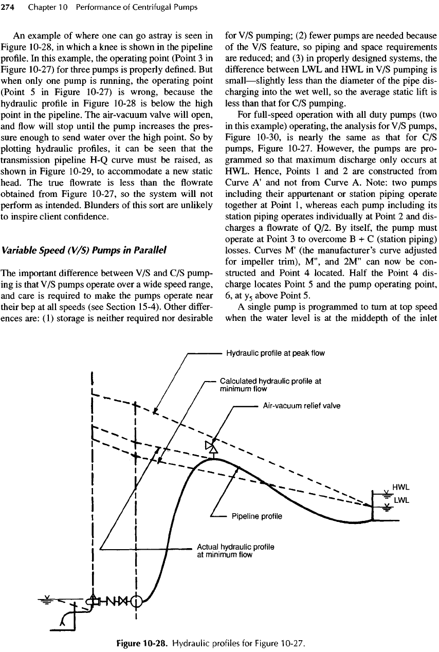
An
example
of
where
one can go
astray
is
seen
in
Figure 10-28,
in
which
a
knee
is
shown
in the
pipeline
profile.
In
this example,
the
operating point (Point
3 in
Figure 10-27)
for
three pumps
is
properly
defined.
But
when
only
one
pump
is
running,
the
operating point
(Point
5 in
Figure 10-27)
is
wrong, because
the
hydraulic
profile
in
Figure 10-28
is
below
the
high
point
in the
pipeline.
The
air-vacuum valve will open,
and
flow
will stop until
the
pump increases
the
pres-
sure enough
to
send water over
the
high point.
So by
plotting
hydraulic profiles,
it can be
seen that
the
transmission pipeline
H-Q
curve must
be
raised,
as
shown
in
Figure 10-29,
to
accommodate
a new
static
head.
The
true
flowrate is
less than
the flowrate
obtained
from
Figure 10-27,
so the
system will
not
perform
as
intended. Blunders
of
this sort
are
unlikely
to
inspire client confidence.
Variable
Speed
(V/S)
Pumps
in
Parallel
The
important
difference
between
V/S and C/S
pump-
ing
is
that
V/S
pumps operate over
a
wide speed range,
and
care
is
required
to
make
the
pumps operate near
their
bep at all
speeds (see Section
15-4).
Other
differ-
ences are:
(1)
storage
is
neither required
nor
desirable
for
V/S
pumping;
(2)
fewer
pumps
are
needed because
of
the V/S
feature,
so
piping
and
space requirements
are
reduced;
and (3) in
properly designed systems,
the
difference
between
LWL and HWL in V/S
pumping
is
small
—
slightly
less than
the
diameter
of the
pipe dis-
charging into
the wet
well,
so the
average static
lift
is
less than that
for C/S
pumping.
For
full-speed operation with
all
duty pumps (two
in
this example) operating,
the
analysis
for V/S
pumps,
Figure
10-30,
is
nearly
the
same
as
that
for C/S
pumps,
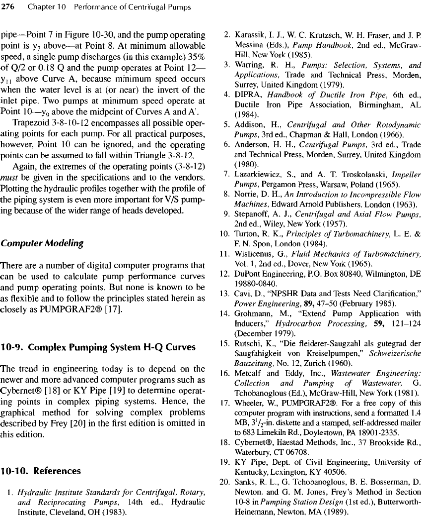
Figure 10-27. However,
the
pumps
are
pro-
grammed
so
that maximum discharge only occurs
at
HWL. Hence, Points
1 and 2 are
constructed
from
Curve
A'
and not
from
Curve
A.
Note:
two
pumps
including their appurtenant
or
station piping operate
together
at
Point
1,
whereas each pump including
its
station piping operates individually
at
Point
2 and
dis-
charges
a flowrate of
Q/2.
By
itself,
the
pump must
operate
at
Point
3 to
overcome
B + C
(station piping)
losses. Curves
M'
(the manufacturer's curve adjusted
for
impeller trim),
M",
and
2M"
can now be
con-
structed
and
Point
4
located. Half
the
Point
4
dis-
charge locates Point
5 and the
pump operating point,
6, at
y
5
above Point
5.
A
single pump
is
programmed
to
turn
at top
speed
when
the
water level
is at the
middepth
of the
inlet
Figure
10-28.
Hydraulic
profiles
for
Figure
10-27.
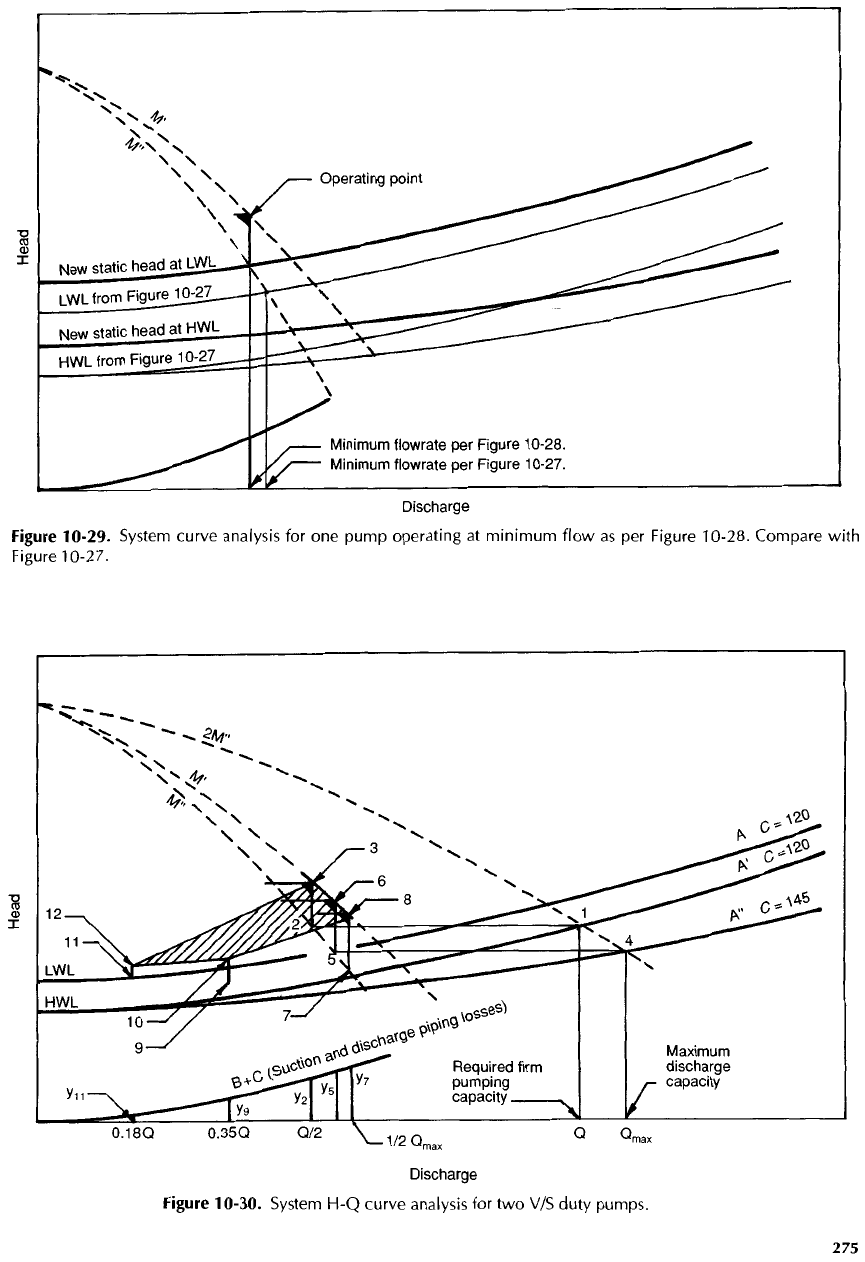
Figure
10-29.
System
curve
analysis
for one
pump
operating
at
minimum
flow
as per
Figure
10-28.
Compare
with
Figure
10-27.
Figure
10-30.
System
H-Q
curve analysis
for two V/S
duty
pumps.
pipe
—
Point
7 in
Figure
10-30,
and the
pump operating
point
is
y
7
above
—
at
Point
8. At
minimum allowable
speed,
a
single pump discharges
(in
this example)
35%
of
Q/2 or
0.18
Q and the
pump operates
at
Point
12
—
y
n
above Curve
A,
because minimum speed occurs
when
the
water level
is at (or
near)
the
invert
of the
inlet
pipe.
Two
pumps
at
minimum speed operate
at
Point
10
—
y
9
above
the
midpoint
of
Curves
A and
A'.
Trapezoid
3-8-10-12
encompasses
all
possible oper-
ating
points
for
each pump.
For all
practical purposes,
however, Point
10 can be
ignored,
and the
operating
points
can be
assumed
to
fall
within
Triangle 3-8-12.
Again,
the
extremes
of the
operating points
(3-8-12)
must
be
given
in the
specifications
and to the
vendors.
Plotting
the
hydraulic
profiles
together
with
the
profile
of
the
piping system
is
even more important
for V/S
pump-
ing
because
of the
wider range
of
heads developed.
Computer
Modeling
There
are a
number
of
digital computer programs that
can
be
used
to
calculate pump performance curves
and
pump operating points.
But
none
is
known
to be
as
flexible and to
follow
the
principles stated herein
as
closely
as
PUMPGRAF2®
[17].
10-9.
Complex
Pumping
System
H-Q
Curves
The
trend
in
engineering today
is to
depend
on the
newer
and
more advanced computer programs such
as
Cybernet®
[18]
or KY
Pipe
[19]
to
determine operat-
ing
points
in
complex piping systems. Hence,
the
graphical method
for
solving complex problems
described
by
Frey [20]
in the first
edition
is
omitted
in
this
edition.
10-10.
References
1
.
Hydraulic Institute Standards
for
Centrifugal,
Rotary,
and
Reciprocating Pumps,
14th ed.,
Hydraulic
Institute,
Cleveland,
OH
(1983).
2.
Karassik,
I.
J.,
W. C.
Krutzsch,
W. H.
Fraser,
and J. P.
Messina
(Eds.),
Pump Handbook,
2nd
ed.,
McGraw-
Hill,
New
York
(1985).
3.
Warring,
R.
H.,
Pumps: Selection, Systems,
and
Applications, Trade
and
Technical Press, Morden,
Surrey,
United Kingdom (1979).
4.
DIPRA, Handbook
of
Ductile Iron Pipe,
6th
ed.,
Ductile
Iron Pipe Association, Birmingham,
AL
(1984).
5.
Addison,
H.,
Centrifugal
and
Other
Rotodynamic
Pumps,
3rd
ed.,
Chapman
&
Hall, London (1966).
6.
Anderson,
H.
H.,
Centrifugal
Pumps,
3rd
ed.,
Trade
and
Technical Press, Morden, Surrey, United Kingdom
(1980).
7.
Lazarkiewicz,
S.,
and A. T.
Troskolanski, Impeller
Pumps, Pergamon Press, Warsaw, Poland (1965).
8.
Norrie,
D.
H.,
An
Introduction
to
Incompressible Flow
Machines, Edward Arnold Publishers, London (1963).
9.
Stepanoff,
A.
J.,
Centrifugal
and
Axial Flow Pumps,
2nd
ed.,
Wiley,
New
York
(1957).
10.
Turton,
R.
K.,
Principles
of
Turbomachinery,
L. E. &
F.
N.
Spon, London
(1984).
11.
Wislicenus,
G.,
Fluid Mechanics
of
Turbomachinery,
Vol.
1,
2nd
ed.,
Dover,
New
York
(1965).
12.
DuPont Engineering,
P.O.
Box
80840,
Wilmington,
DE
19880-0840.
13.
Cavi,
D.,
"NPSHR Data
and
Tests Need Clarification,"
Power
Engineering,
89,
47-50
(February 1985).
14.
Grohmann,
M.,
"Extend Pump Application with
Inducers,"
Hydrocarbon Processing,
59,
121-124
(December 1979).
15.
Rutschi,
K.,
"Die
fleiderer-Saugzahl
als
gutegrad
der
Saugfahigkeit
von
Kreiselpumpen,"
Schweizerische
Bauzeitung,
No. 12,
Zurich (1960).
16.
Metcalf
and
Eddy,
Inc.,
Wastewater Engineering:
Collection
and
Pumping
of
Wastewater,
G.
Tchobanoglous
(Ed.),
McGraw-Hill,
New
York
(1981).
17.
Wheeler,
W,
PUMPGRAF2®.
For a free
copy
of
this
computer program with instructions, send
a
formatted
1
.4
MB,
3V
2
-in.
diskette
and a
stamped, self-addressed mailer
to
683
Limekiln
Rd.,
Doylestown,
PA
18901-2335.
18.
Cybernet®, Haestad Methods,
Inc.,
37
Brookside
Rd.,
Waterbury,
CT
06708.
19.
KY
Pipe, Dept.
of
Civil Engineering, University
of
Kentucky,
Lexington,
KY
40506.
20.
Sanks,
R.
L.,
G.
Tchobanoglous,
B. E.
Bosserman,
D.
Newton,
and G. M.
Jones,
Prey's
Method
in
Section
10-8
in
Pumping Station Design
(1st
ed.),
Butterworm-
Heinemann, Newton,
MA
(1989).
The
types
of
pumps commonly used
in
public utilities
for
the
pumping
of
water,
wastewater,
and
sludge
are
described
in
this chapter together with details such
as
impellers, cas-
ings,
seals,
and
wear rings.
A
summary
of
pump sizes
and
applications
is
given
in
Section
11-11,
and a
general com-
parison
of
advantages
and
disadvantages
of the
pumps
is
presented
in
Section 25-6.
A
more complete listing
of
pump
parts
is
given
by the
Hydraulic Institute
[1,
2].
For
pump
dimensions
and
performance data,
refer
to the
pump
manufacturers'
catalogs. Examples
of
pump selection
are
presented
in
Chapters
12,
17,
18,
19,
26,
and 29.
References
to
standards
are
given
in
abbreviated
form,
such
as
ANSI B73.1.
See
Appendix
E for a
list-
ing of
titles
of
standards
useful
for
selecting
and
spec-
ifying
pumps
and
Appendix
F for the
addresses
of the
publishers
of the
standards.
11-1.
General
Classifications
of
Pumps
Pumps
may be
classified
in
many different ways.
Classification
by
general mechanical configuration
is
Chapter
1 1
Types
of
Pumps
RICHARD
O.
GARBUS
CONTRIBUTORS
Kirk
Blanchard
Rodney
L.
Cusworth
Kundan
Desai
Mayo
Gottliebson
David
A.
House
Joseph
K.
Jackson
R.
Russell
Langteau
Colin
Martin
Stephen
G.
Miller
Lowell
G.
Sloan
Earle
C.
Smith
Robert
E.
Starke
used
in
this chapter. Figure
11-1
(an
abridged version
of
the
more complete listing given
by the
Hydraulic
Institute
[I])
is a
chart
of the
pumps discussed here
arranged according
to
their design.
A
slightly
different
version
of
Figure
11-1
is
given
in a
later edition
of
Hydraulic
Institute
Standards [2],
but it
offers
no
advantage
for
this chapter.
An
overview
of
pumps
is
given
in the
following subsections.
The
pumps
are
described
in
more detail
in
Sections
11-3
to
11-10.
There
are two
basic
groups
of
pumps:
(1)
kinetic
and
(2)
positive displacement.
Kinetic
Pumps
Kinetic pumps impart velocity
and
pressure
to the
fluid
as
it
moves past
or
through
the
pump impeller
and, subsequently, convert some
of
that velocity into
additional pressure. Kinetic pumps
are
subdivided
into
two
major groups:
(1)
centrifugal
(or
volute)
and
(2)
vertical
(or
turbine) pumps.
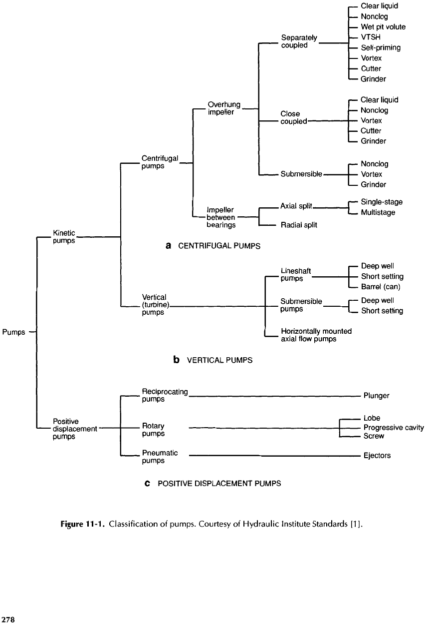
Figure
11-1.
Classification
of
pumps. Courtesy
of
Hydraulic Institute Standards
[1].
Centrifugal
Pumps
All
centrifugal
pumps have
one
common feature:
they
are
equipped
with
a
volute
or
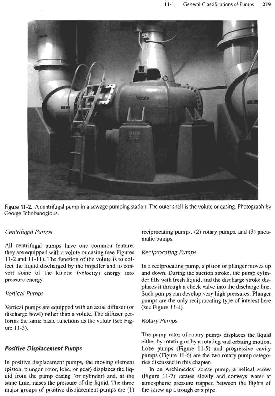
casing (see Figures
11-2
and
11-11).
The
function
of the
volute
is to
col-
lect
the
liquid discharged
by the
impeller
and to
con-
vert
some
of the
kinetic (velocity) energy into
pressure
energy.
Vertical
Pumps
Vertical
pumps
are
equipped with
an
axial
diffuser
(or
discharge bowl) rather than
a
volute.
The
diffuser
per-
forms
the
same basic
functions
as the
volute (see Fig-
ure
11
-3).
Positive
Displacement
Pumps
In
positive displacement pumps,
the
moving element
(piston,
plunger, rotor, lobe,
or
gear) displaces
the
liq-
uid
from
the
pump casing
(or
cylinder) and,
at the
same time, raises
the
pressure
of the
liquid.
The
three
major
groups
of
positive displacement pumps
are (1)
reciprocating pumps,
(2)
rotary pumps,
and (3)
pneu-
matic pumps.
Reciprocating Pumps
In
a
reciprocating pump,
a
piston
or
plunger moves
up
and
down. During
the
suction stroke,
the
pump cylin-
der fills
with
fresh
liquid,
and the
discharge stroke dis-
places
it
through
a
check valve into
the
discharge line.
Such pumps
can
develop very high pressures. Plunger
pumps
are the
only reciprocating type
of
interest here
(see Figure
11-4).
Rotary
Pumps
The
pump rotor
of
rotary pumps displaces
the
liquid
either
by
rotating
or by a
rotating
and
orbiting motion.
Lobe pumps (Figure
11-5)
and
progressive cavity
pumps
(Figure
11-6)
are the two
rotary pump catego-
ries
discussed
in
this chapter.
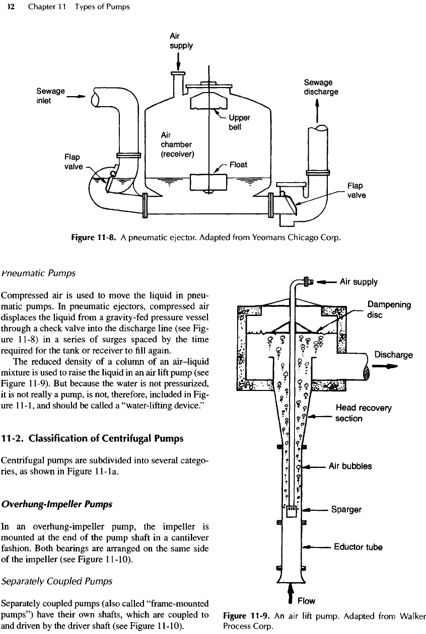
In an
Archimedes' screw pump,
a
helical screw
(Figure
11-7)
rotates slowly
and
conveys water
at
atmospheric pressure trapped between
the flights of
the
screw
up a
trough
or a
pipe.
Figure
11-2.
A
centrifugal
pump
in a
sewage
pumping
station.
The
outer
shell
is the
volute
or
casing.
Photograph
by
George
Tchobanoglous.
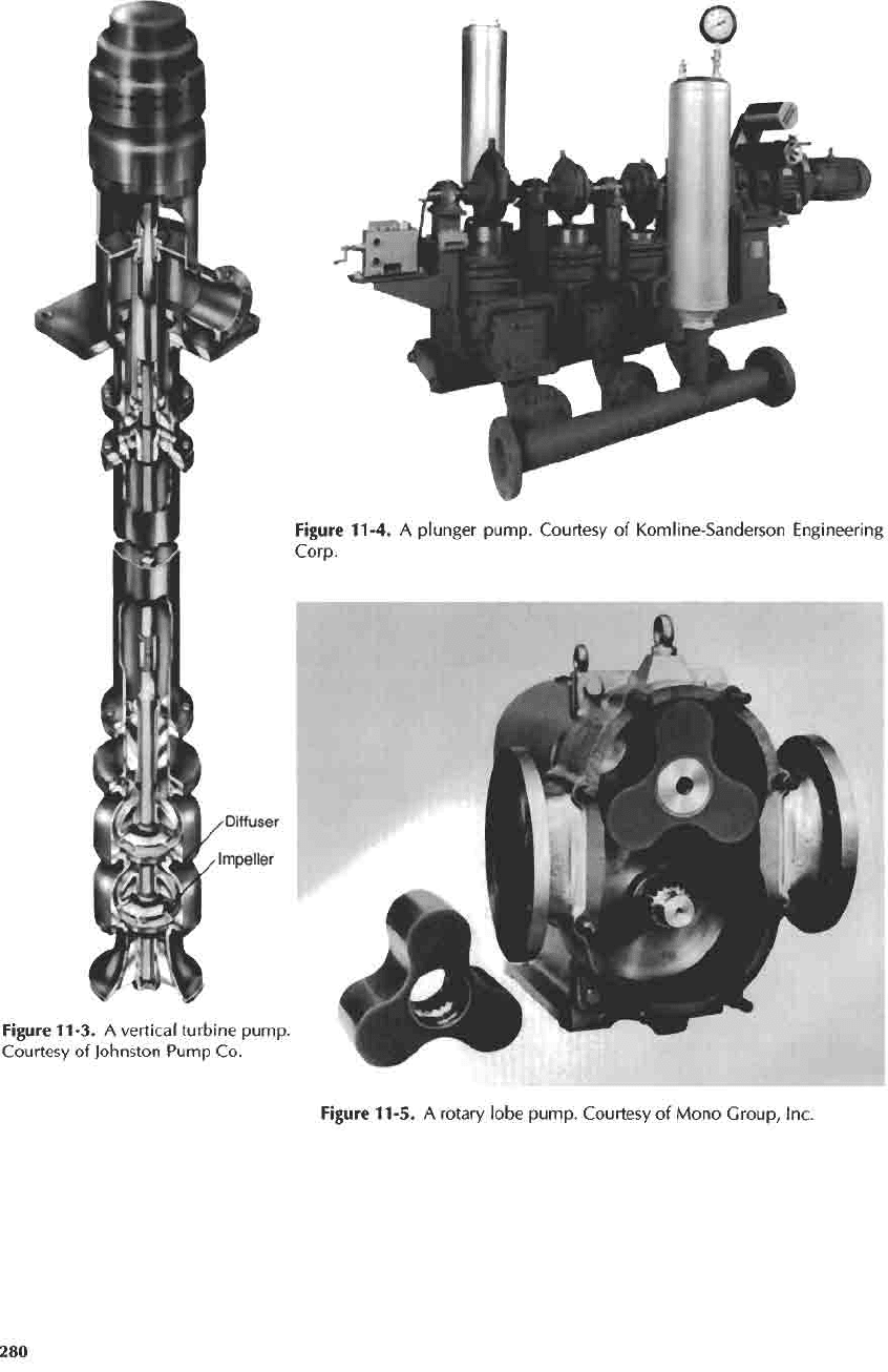
Figure
11-4.
A
plunger
pump.
Courtesy
of
Komline-Sanderson Engineering
Corp.
Figure
11-3.
A
vertical
turbine
pump.
Courtesy
of
Johnston Pump
Co.
Figure
11-5.
A
rotary
lobe
pump.
Courtesy
of
Mono
Group,
Inc.
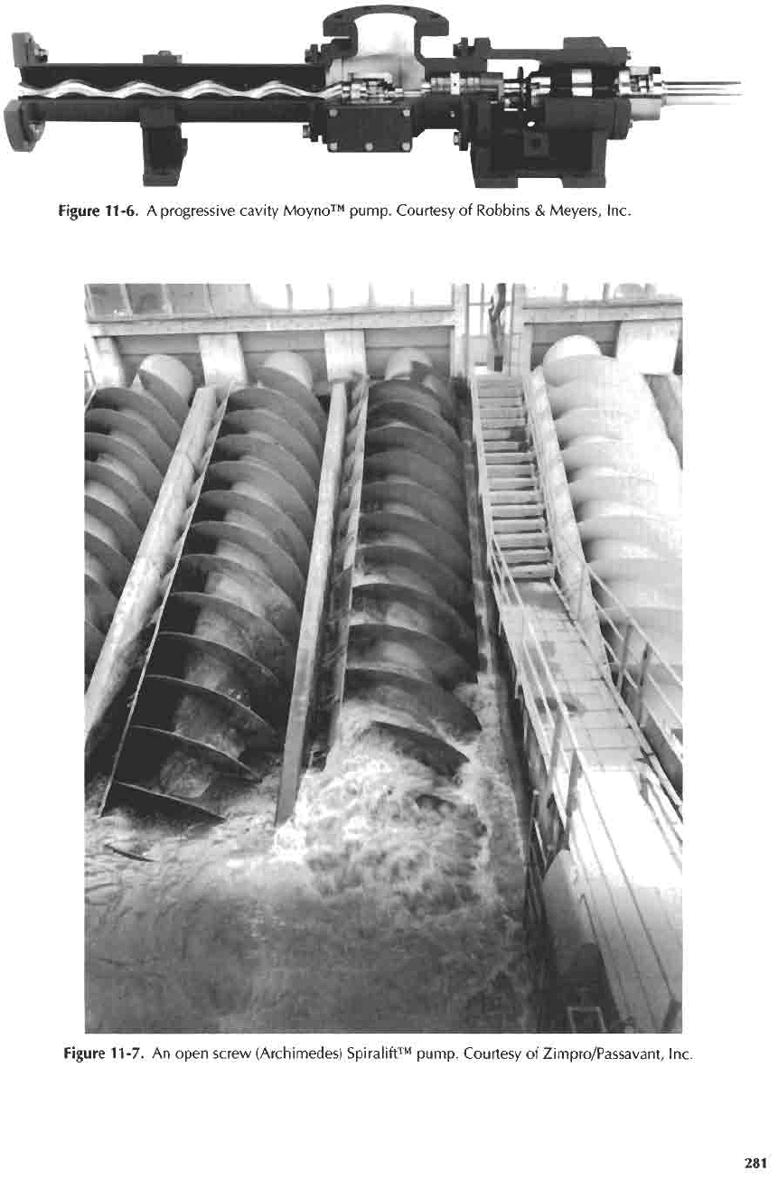
Figure 11-6.
A
progressive cavity
Moyno™
pump.
Courtesy
of
Robbins
&
Meyers,
Inc.
Figure
11-7.
An
open
screw (Archimedes)
Spiralift™
pump.
Courtesy
of
Zimpro/Passavant,
Inc.
Pneumatic
Pumps
Compressed
air is
used
to
move
the
liquid
in
pneu-
matic pumps.
In
pneumatic ejectors, compressed
air
displaces
the
liquid
from
a
gravity-fed pressure vessel
through
a
check valve into
the
discharge line (see Fig-
ure
11-8)
in a
series
of
surges spaced
by the
time
required
for the
tank
or
receiver
to fill
again.
The
reduced density
of a
column
of an
air—
liquid
mixture
is
used
to
raise
the
liquid
in an air
lift
pump (see
Figure
11-9).
But
because
the
water
is not
pressurized,
it
is not
really
a
pump,
is
not, therefore, included
in
Fig-
ure
11-1,
and
should
be
called
a
"water-lifting
device."
11-2.
Classification
of
Centrifugal
Pumps
Centrifugal
pumps
are
subdivided into several catego-
ries,
as
shown
in
Figure
11-la.
Overhung-lmpeller
Pumps
In an
overhung-impeller pump,
the
impeller
is
mounted
at the end of the
pump
shaft
in a
cantilever
fashion.
Both bearings
are
arranged
on the
same side
of
the
impeller (see Figure
1
1-10).
Separately
Coupled
Pumps
Separately coupled pumps (also called "frame-mounted
pumps") have their
own
shafts,
which
are
coupled
to
and
driven
by the
driver
shaft
(see Figure
1
1-10).
Figure
11-9.
An air
lift
pump.
Adapted
from
Walker
Process
Corp.
Figure 11-8.
A
pneumatic
ejector.
Adapted
from
Yeomans Chicago
Corp.
