Pumping Station Desing - Second Edition by Robert L. Sanks, George Tchobahoglous, Garr M. Jones
Подождите немного. Документ загружается.

suction
nozzle
of the
pump
and
referenced
to the
pump
datum elevation
and
atmospheric pressure.
Manometric
discharge head
(h
gd
):
The
discharge
gauge
reading
is
expressed
in
meters
(feet)
measured
at
the
discharge nozzle
of the
pump
and
referenced
to the
centerline
of the
pump impeller.
The
gauge
reading
is the
height that
a
water column would
attain
in a
vertical pipe.
It is
also
the
distance
to the
hydraulic
gradeline (shown dashed
in
Figures 10-2
and
10-3).
Manometric
head
(//
g
):
This
is the
increase
of
pressure
head, expressed
in
meters
(feet)
generated
by
the
pump
(fc
gd
-
/i
gs
).
Friction
headloss
(h
fs
,
/z
hd
):
This
is the
head
of
water
that
must
be
supplied
to
overcome
the
frictional
loss
in the
pipe.
The
frictional
headloss
in the
suction
(h
fs
)
and
discharge
(h
fd
)
piping systems
can be
com-
puted with
the
Hazen-Williams
or
Darcy-Weisbach
equations
(Equations
3-9 and
3-10).
Velocity
head
(v
2
/2g):
The
velocity head
is the
kinetic energy
in the
liquid being pumped
at any
point
in the
system.
The
energy gradeline (shown
solid
in
Figures 10-2
and
10-3)
is
always above
the
hydraulic
or
piezometric
or
manometric
gradeline
(dashed line)
by
v
2
/2g.
The
velocity head
in the
dis-
charge pipe,
v\
/2g is
lost
if the
pipe discharges
freely
in air or if it
discharges abruptly below
the
sur-
face
of a
reservoir. Some
of the
velocity head
can be
recovered
if
turbulence
is
inhibited
by a
gradually
expanding section,
but
this
is
ordinarily
impractical
with
the
pipe velocities normally encountered (i.e.,
up
to 2.5
m/s
or 8
ft/s).
Fitting
and
valve losses
(h
fvs
,
/i
fvd
):
As a fluid flows
through
fittings and
valves, energy
is
lost
due to
eddy
formation
and
turbulence. Because
the
head lost
in fit-
tings
and
valves
is
small compared with
the
friction
loss
in
long piping systems,
the
losses
in fittings and
valves
are
sometimes called
"minor
losses"
and
often
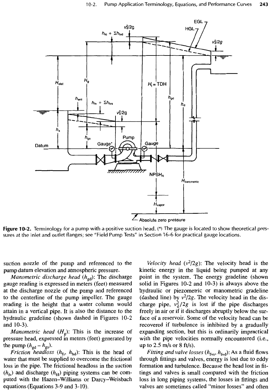
Figure
10-2. Terminology
for a
pump
with
a
positive suction head.
(*) The
gauge
is
located
to
show
theoretical
pres-
sures
at the
inlet
and
outlet
flanges;
see
"Field
Pump
Tests"
in
Section
16-6
for
practical gauge
locations.
ignored.
But the
lengths
of
pipes within
a
pumping
station
are
short,
and the
total headloss through
the fit-
tings
and
valves
is
likely
to be
greater than
the
pipe
friction
loss. Regardless
of the
shortness
of
pipe
length, both
the
frictional headless
and the
"minor
losses"
should always
be
computed.
The
loss
of
head through each individual
fitting or
valve
is
estimated
by
using Equation 3-15
(h =
Kv
2
/2g)
with
K
values taken
from
Tables
B-6
and B-7 (or
from
the
literature).
The
total
fitting and
valve
losses
in the
piping system
are
determined
by
summing
the
individ-
ual
losses
for
each
fitting and
valve,
but,
as
explained
in
Section
3-4,
the
total
may in
reality
be
somewhat
less
or
much greater than this sum.
Total
dynamic
head
(H
1
or
TDPf):
The
total
dynamic
head
is the
head against which
the
pump
must
work.
It is
determined
by
adding
the
static
suc-
tion
and
discharge head (with respect
to
signs),
the
frictional
headlosses,
the
velocity heads,
and the fit-
ting
and
valve headlosses.
The
expression
for
deter-
mining
the
total dynamic head
for the
pumps shown
in
Figures
10-2
and
10-3
is
given
by
Equations
10-1,
10-2,
and
10-3.
2 2
H
*
=
h
#-
h
»
+
Tg-Tg
(1(M)
where
h
gd
=
h
d
+
h
fd
+
I/*
fvd
(10-2)
and
2
^gs
=
^s
-
^ent
~
^fs
-
2*f»
~
~
(10-3)
Substituting Equations
10-2
and
10-3
into Equa-
tion
10-1
and
noting that
h
d
-h
s
=
//
stat
,
H
i
=
H
stat
+
h
ent
+
h
fs
+
h
fd
v
2
(10-4)
+
S/*
frs
+
E/z
fvd
+
^
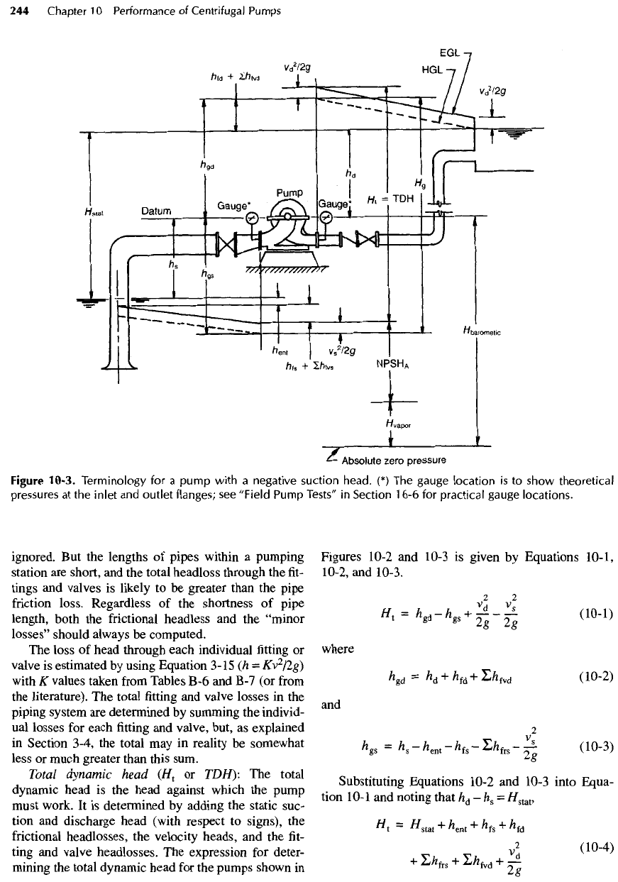
Figure
10-3.
Terminology
for a
pump
with
a
negative suction head.
(*) The
gauge
location
is to
show theoretical
pressures
at the
inlet
and
outlet flanges;
see
"Field Pump
Tests''
in
Section
16-6
for
practical gauge locations.
Some designers consider
all
headlosses
except pipe
friction
to be
"minor"
losses,
/z
m
,
and
rewrite Equation
10-4
as
^
=
#stat
+
^
s
+
^fd
+
2X
(
10
-
5
>
Power
Output Power
The
power output
of a
pump
is the
energy delivered
by
the
pump
to the fluid. In SI
units,
the
power output
is
defined
as
P
=
JQH
=
IJ2
(1
°"
6a)
where
P is the
water power
in
kilowatts,
y
is the
spe-
cific
weight
of the fluid in
kilonewtons
per
cubic
meter (see Table A-8),
Q is the flowrate in
cubic
meters
per
second,
H is the
total dynamic head
in
meters,
q is the flowrate in
liters
per
second,
and 102
is a
conversion
factor
for
water
at 15 to
2O
0
C.
In
U.S.
customary
units, power output
is
defined
as
P
=
TQH
-
WH
_
qH
550
33,000
3960
v
'
where
P is the
water power
in
horsepower,
y is the
specific
weight
of the fluid in
pounds
per
cubic
foot
(see Table A-9),
Q is the flowrate in
cubic
feet
per
sec-
ond,
H is the
total dynamic head
in
feet,
550 is the
conversion
factor
from
foot-pounds
per
second
to
horsepower,
W is
weight
of
water pumped
in
pounds
per
minute,
33,000
is the
conversion factor
from
foot-
pounds
per
minute
to
horsepower,
q is flowrate in
gal-
lons
per
minute,
and
3960
is
used
to
convert gallon
feet
per
minute
to
horsepower.
Input
Power
Pump performance
is
measured
in
terms
of the flow-
rate that
a
pump
can
discharge against
a
given head
at
a
given
efficiency.
The
pump capacity
depends
on the
design,
and
design information
is
furnished
by the
pump
manufacturer
in a
series
of
curves
for a
given
pump. Pump
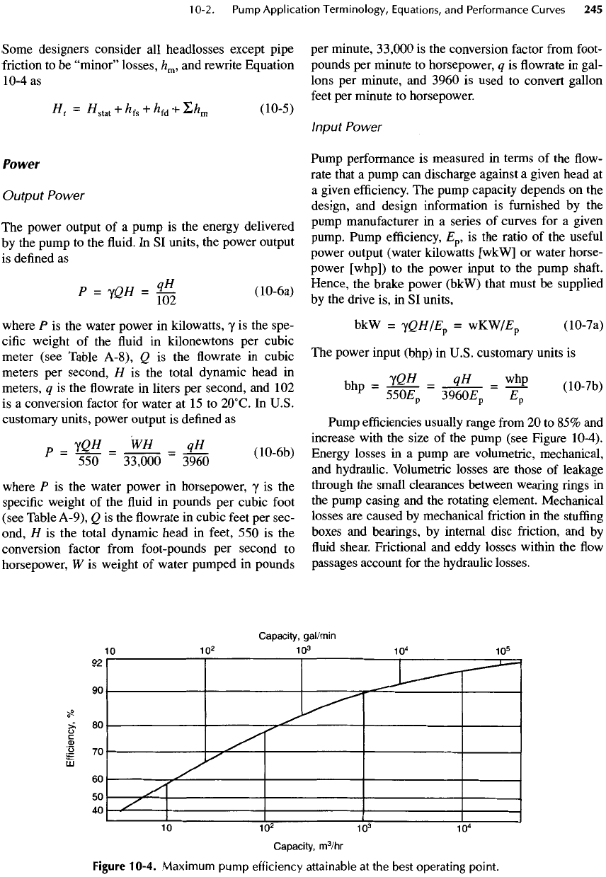
efficiency,
E
p
,
is the
ratio
of the
useful
power output (water kilowatts
[wkW]
or
water horse-
power [whp])
to the
power input
to the
pump
shaft.
Hence,
the
brake power (bkW) that must
be
supplied
by
the
drive
is, in SI
units,
bkW
=
jQH/E
p
=
wKW/£
p
(10-7a)
The
power input (bhp)
in
U.S. customary units
is
bh
=
IQH
=
qH _
whp
P
550£
p
3960E
p
£
p
V
'
Pump
efficiencies
usually range
from
20 to 85% and
increase
with
the
size
of the
pump (see Figure
10-4).
Energy losses
in a
pump
are
volumetric, mechanical,
and
hydraulic. Volumetric losses
are
those
of
leakage
through
the
small clearances between wearing
rings in
the
pump casing
and the
rotating element. Mechanical
losses
are
caused
by
mechanical
friction
in the
stuffing
boxes
and
bearings,
by
internal disc friction,
and by
fluid
shear.
Frictional
and
eddy losses within
the flow
passages account
for the
hydraulic losses.
Figure
10-4.
Maximum
pump
efficiency
attainable
at the
best
operating
point.
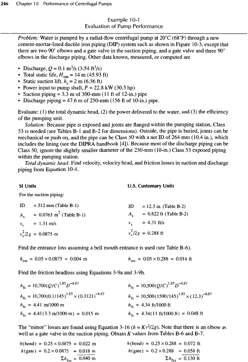
Example
10-1
Evaluation
of
Pump Performance
Problem: Water
is
pumped
by a
radial-flow centrifugal pump
at
2O
0
C
(68
0
F)
through
a new
cement-mortar-lined ductile iron piping (DIP) system such
as
shown
in
Figure 10-3, except that
there
are two 90°
elbows
and a
gate valve
in the
suction piping,
and a
gate valve
and
three
90°
elbows
in the
discharge piping. Other data known, measured,
or
computed
are
•
Discharge,
Q =
0.1
m
3
/s
(3.54
ft
3
/s)
•
Total static
life,
//
stat
= 14 m
(45.93
ft)
•
Static suction
lift,
h
s
= 2 m
(6.56
ft)
•
Power input
to
pump
shaft,
P =
22.8
kW
(30.5
hp)
•
Suction piping
= 3.3 m of
300-mm
(11
ft of
12-in.)
pipe
•
Discharge piping
=
47.6
m of
250-mm (156
ft of
10-in.)
pipe.
Evaluate:
(1)
the
total dynamic head,
(2) the
power delivered
to the
water,
and (3) the
efficiency
of
the
pumping unit.
Solution: Because pipe
is
exposed
and
joints
are flanged
within
the
pumping station, Class
53
is
needed (see Tables
B-I
and B-2 for
dimensions). Outside,
the
pipe
is
buried, joints
can be
mechanical
or
push
on, and the
pipe
can be
Class
50
with
a net ID of 264 mm
(10.4
in.),
which
includes
the
lining (see
the
DIPRA handbook
[4]).
Because most
of the
discharge piping
can be
Class
50,
ignore
the
slightly smaller diameter
of the
250-mm (10-in.) Class
53
exposed piping
within
the
pumping station.
Total
dynamic
head: Find velocity, velocity head,
and
friction
losses
in
suction
and
discharge
piping
from
Equation 10-4.
Sl
Units
U.S. Customary
Units
For the
suction
piping:
ID
= 312 mm
(Table
B-I)
ID =
12.3
in.
(Table B-2)
A
5
=
0.0763
m
2
(Table
B-I)
^
8
=
°-
822
ft
(
Table
B
'
2
)
v
s
=1.31
m/s
V
8
=
4.31 ft/s
v
2
s
/2g
=
0.0875
m
v
2
s
P,g
=
0.288
ft
Find
the
entrance loss assuming
a
bell mouth entrance
is
used (see Table B-6).
/*
ent
=
0.05
x
0.0875
=
0.004
m
/*
ent
=
0.05
x
0.288
=
0.014
ft
Find
the
friction headloss using Equations 3-9a
and
3-9b.
/z
fs
=
10,700(2/C)
1
'
85
D~
4
'
87
h
fs
=
10,500(G/C)
L85
£T
4
'
87
h
f&
=
10,700(0.1/145)
L85
x
(0.3121)~
4
-
87
h
fs
=
10,500(1590/145)
L85
x
(12.3)~
4<87
h
fs
=
4.41
m/lOOOm
h
fs
=
4.34
ft/1000
ft
h
fs
=
4.41(3.3
m/lOOOm)
=
0.015
m
h
f&
=
4.34(11
ft/1000
ft) =
0.048
ft
The
"minor"
losses
are
found
using Equation 3-16
(h =
Kv
2
/2g).
Note that there
is an
elbow
as
well
as a
gate valve
in the
suction piping. Obtain
K
values
from
Tables
B-6 and
B-7.
/z(bend)
=
0.25x0.0875
=
0.022
m
/z(bend)
=
0.25x0.288
=
0.072
ft
/z(gate)
=
0.2x0.0875
=
0.018
m
A
(gate)
=
0.2x0.288
=
0.058
ft
Z/z
fvs
=
0.040
m
Z/*
fvs
=
0.130ft
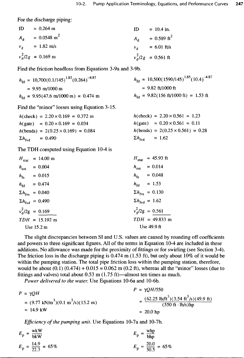
For the
discharge piping:
ID =
0.264
m ID =
10.4
in.
A
d
=
0.0548
m
2
A
d
=
0.589
ft
2
v
d
=
1.82
m/s
v
d
=
6.01
ft/s
v
d
/2#
=
0.169m
v
d
/2g
=
0.561
ft
Find
the
friction headloss
from
Equations
3-9a
and
3-9b.
h
fd
=
10,700(0.1/145)
L85
(0.264)-
4
'
87
h
fd
=
10,500(
1590/145)
L85
(10.4)-
4
'
87
=
9.95
m/1000
m =
9.82 ft/1000
ft
h
fd
=
9.95(47.6
m/1000
m) =
0.474
m
h
fd
=
9.82(156
ft/1000
ft) =
1.53
ft
Find
the
"minor"
losses using Equation 3-15.
/K
check)
=
2.20x0.169
=
0.372m
/K
check)
=
2.20x0.561
=
1.23
/z(gate)
=
0.20x0.169
=
0.034
A
(gate)
=
0.20x0.561
=
0.11
/i(bends)
=
2(0.25x0.169)
=
0.084
fc
(bends)
=
2(0.25x0.561)
=
0.28
Z/z
fvd
=
0.490
S/*
fvd
=
1.62
The TDH
computed using Equation
10-4
is
//
stat
=
14.00
m
//
stat
=
45.93
ft
/W
=
O-OO
4
*W
-
0.014
h
fs
=0.015
h
fs
=
0.048
h
fd
=
0.474
h
fd
=
1.53
I/z
fvs
=
0.040
Z/z
fvs
=0.130
L/z
fvd
=
0.490
£/*
fvd
=
1.62
v
d
/2g
=
0.169
v
d
/2g
=
0.561
TDH
=
15.192
m TDH =
49.833
m
Use
15.2m
Use
49.9
ft
The
slight discrepancies between
SI and
U.S. values
are
caused
by
rounding
off
coefficients
and
powers
to
three
significant
figures.
All of the
terms
in
Equation
10-4
are
included
in
these
additions.
No
allowance
was
made
for the
proximity
of fittings or for
swirling
(see
Section
3-4).
The
friction
loss
in the
discharge piping
is
0.474
m
(1.53
ft),
but
only about
10% of it
would
be
within
the
pumping station.
The
total pipe friction loss within
the
pumping station, therefore,
would
be
about
(0.1)
(0.474)
+
0.015
=
0.062
m
(0.2
ft), whereas
all the
"minor"
losses
(due
to
fittings
and
valves) total about
0.53
m
(1.75
ft)—almost
ten
times
as
much.
Power
delivered
to the
water.
Use
Equations
10-6a
and
10-6b.
p
=
yg///550
P
= JQH 3
,
3
3
(62.25
Ib/ft
)(3.54
ft/s)
(49.9
ft)
=
(9.77
kN/m
3
)(0.1
m
3
/s)(15.2
m)
=
(550
ft
•
lb/s)hp
=
14
'
9kW
=20.0hp
Efficiency
of
the
pumping unit.
Use
Equations 10-7a
and
10-7b.
...
_ wkW
J
7
_ whp
P
~
bkW
P
~
bhp
•,-58-««
'.
=
!
=
«*
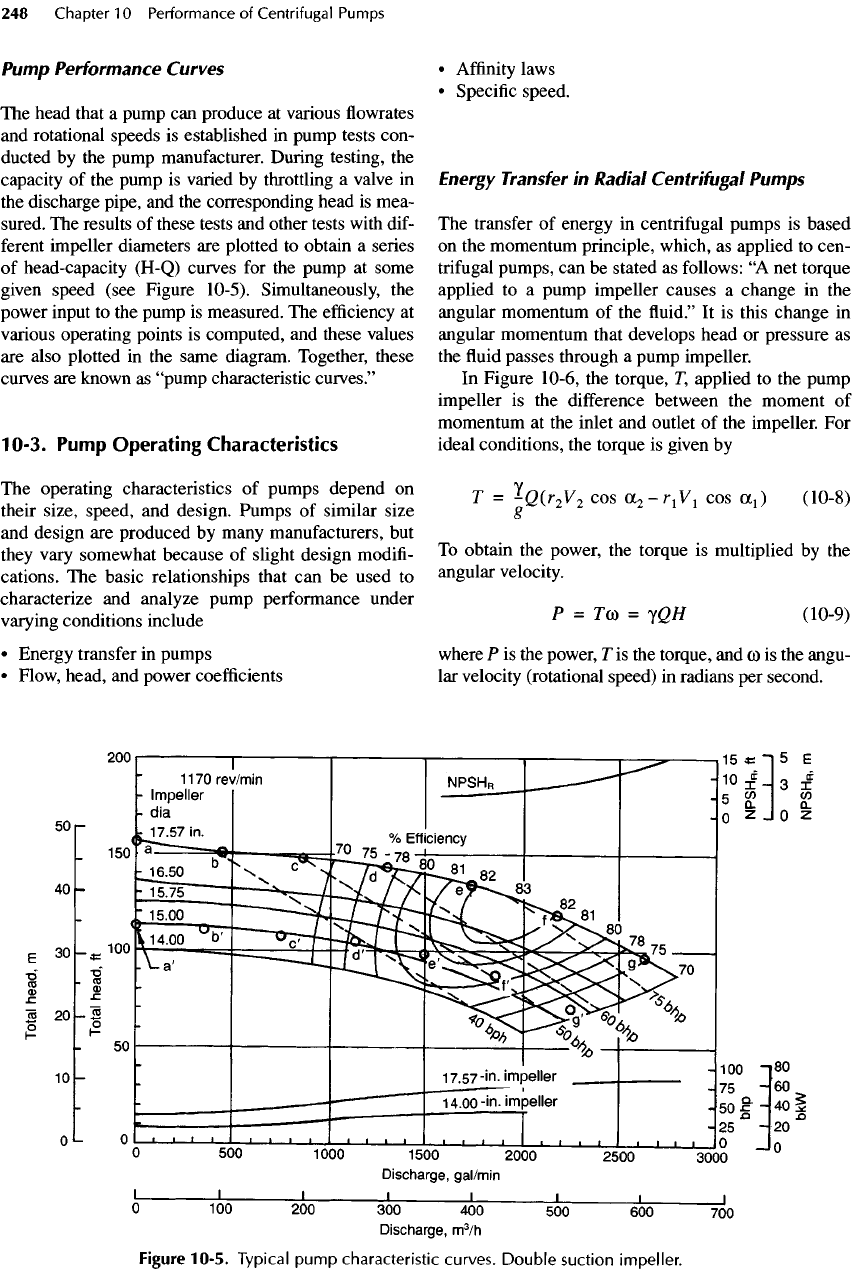
Pump
Performance
Curves
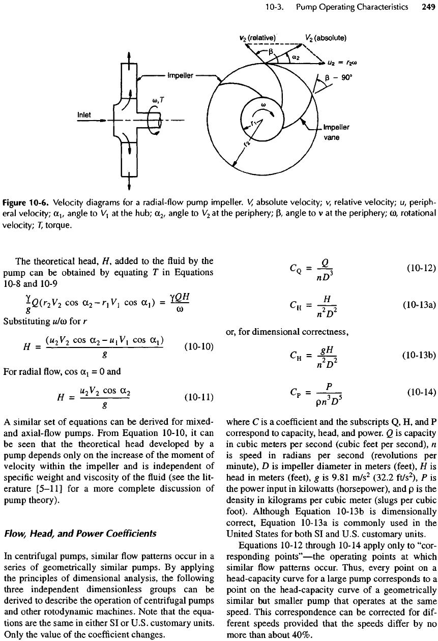
The
head that
a
pump
can
produce
at
various
flowrates
and
rotational speeds
is
established
in
pump tests
con-
ducted
by the
pump manufacturer. During testing,
the
capacity
of the
pump
is
varied
by
throttling
a
valve
in
the
discharge pipe,
and the
corresponding head
is
mea-
sured.
The
results
of
these tests
and
other tests with
dif-
ferent
impeller diameters
are
plotted
to
obtain
a
series
of
head-capacity
(H-Q)
curves
for the
pump
at
some
given
speed
(see
Figure 10-5). Simultaneously,
the
power input
to the
pump
is
measured.
The
efficiency
at
various
operating points
is
computed,
and
these values
are
also plotted
in the
same diagram. Together, these
curves
are
known
as
"pump characteristic curves."
10-3.
Pump
Operating Characteristics
The
operating characteristics
of
pumps depend
on
their size, speed,
and
design. Pumps
of
similar size
and
design
are
produced
by
many manufacturers,
but
they
vary somewhat because
of
slight design
modifi-
cations.
The
basic relationships that
can be
used
to
characterize
and
analyze pump performance under
varying
conditions include
•
Energy transfer
in
pumps
•
Flow, head,
and
power
coefficients
•
Affinity
laws
•
Specific
speed.
Energy
Transfer
in
Radial
Centrifugal
Pumps
The
transfer
of
energy
in
centrifugal pumps
is
based
on
the
momentum principle, which,
as
applied
to
cen-
trifugal
pumps,
can be
stated
as
follows:
"A
net
torque
applied
to a
pump impeller causes
a
change
in the
angular momentum
of the fluid." It is
this change
in
angular momentum that develops head
or
pressure
as
the
fluid
passes through
a
pump impeller.
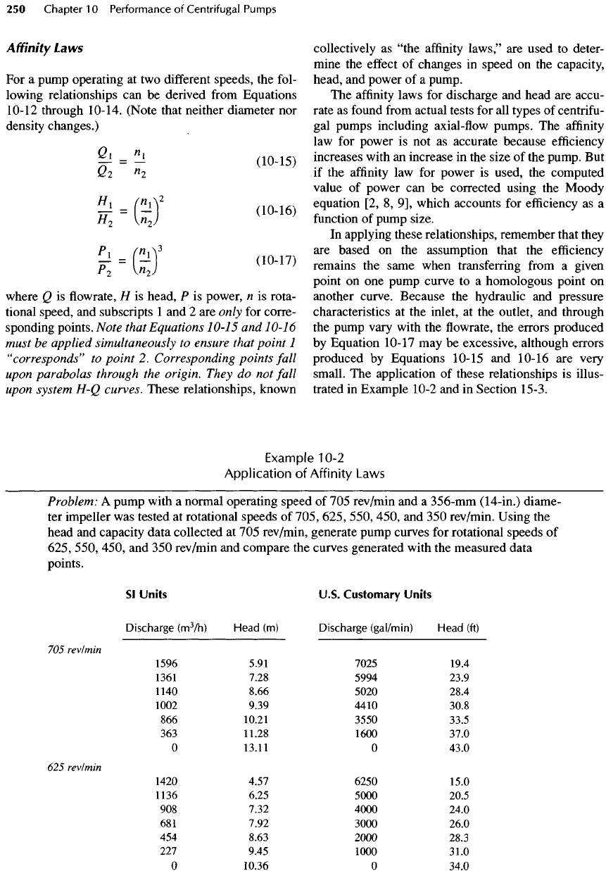
In
Figure
10-6,
the
torque,
T,
applied
to the
pump
impeller
is the
difference between
the
moment
of
momentum
at the
inlet
and
outlet
of the
impeller.
For
ideal conditions,
the
torque
is
given
by
T =
^Q(r
2
V
2
cos
OC
2
-T
1
V
1
cos
OL
1
)
(10-8)
O
To
obtain
the
power,
the
torque
is
multiplied
by the
angular velocity.
P
=
Tco
=
yQH
(10-9)
where
P is the
power,
T is the
torque,
and
co
is the
angu-
lar
velocity (rotational speed)
in
radians
per
second.
Figure
10-5.
Typical
pump
characteristic curves.
Double
suction
impeller.
The
theoretical head,
H
1
added
to the fluid by the
pump
can be
obtained
by
equating
T in
Equations
10-8
and
10-9
JgCr
2
V
2
cos
(X
2
-T
1
V
1
cos
a,)
=
^
Substituting
w/co
for r
H
=
(U
2
V
2
cosa
2
-^
1
V
1
COSa
1
)
g
For
radial
flow, cos
Cc
1
= O and
H
=
^
C
°
S
^
(10-11)
8
A
similar
set of
equations
can be
derived
for
mixed-
and
axial-flow pumps. From Equation
10-10,
it can
be
seen that
the
theoretical head developed
by a
pump
depends only
on the
increase
of the
moment
of
velocity within
the
impeller
and is
independent
of
specific
weight
and
viscosity
of the fluid
(see
the
lit-
erature
[5-11]
for a
more complete discussion
of
pump
theory).
Flow,
Head,
and
Power
Coefficients
In
centrifugal pumps, similar
flow
patterns occur
in a
series
of
geometrically similar pumps.
By
applying
the
principles
of
dimensional analysis,
the
following
three independent dimensionless groups
can be
derived
to
describe
the
operation
of
centrifugal pumps
and
other
rotodynamic
machines. Note that
the
equa-
tions
are the
same
in
either
SI or
U.S. customary units.
Only
the
value
of the
coefficient
changes.
CQ
=
-&-.
(10-12)
nD*
CH
=
-f-
2
(10-13a)
n D
or,
for
dimensional correctness,
Q
=
-ft
(10-13b)
n D
Cp
=
-|-
5
dO-14)
pn
D
where
C is a
coefficient
and the
subscripts
Q, H, and P
correspond
to
capacity, head,
and
power.
Q is
capacity
in
cubic meters
per
second (cubic feet
per
second),
n
is
speed
in
radians
per
second (revolutions
per
minute),
D is
impeller diameter
in
meters (feet),
H is
head
in
meters (feet),
g is
9.81
m/s
2
(32.2
ft/s
2
),
P is
the
power input
in
kilowatts (horsepower),
and p is the
density
in
kilograms
per
cubic meter (slugs
per
cubic
foot).
Although Equation
10-13b
is
dimensionally
correct, Equation
10-13a
is
commonly used
in the
United
States
for
both
SI and
U.S.
customary units.
Equations
10-12
through
10-14
apply only
to
"cor-
responding
points"
—
the
operating points
at
which
similar
flow
patterns occur. Thus, every point
on a
head-capacity curve
for a
large pump corresponds
to a
point
on the
head-capacity curve
of a
geometrically
similar
but
smaller pump that operates
at the
same
speed. This correspondence
can be
corrected
for
dif-
ferent
speeds provided that
the
speeds
differ
by no
more than about
40%.
Figure
10-6. Velocity diagrams
for a
radial-flow pump impeller.
V
1
absolute velocity;
v,
relative velocity;
u,
periph-
eral
velocity;
(X
1
,
angle
to
V
1
at the
hub;
Ct
2
,
angle
to
V
2
at the
periphery;
P,
angle
to v at the
periphery;
u),
rotational
velocity;
T
1
torque.
Affinity
Laws
For a
pump operating
at two
different
speeds,
the
fol-
lowing
relationships
can be
derived
from
Equations
10-12
through
10-14.
(Note that neither diameter
nor
density
changes.)
%
=
^
(10-15)
Q
2
n
2
£
-
O
2
£
-
©'
where
Q is flowrate, H is
head,
P is
power,
n is
rota-
tional speed,
and
subscripts
1 and 2 are
only
for
corre-
sponding points. Note that Equations 10-15
and
10-16
must
be
applied
simultaneously
to
ensure that
point
1
"corresponds"
to
point
2.
Corresponding points fall
upon
parabolas through
the
origin.
They
do not
fall
upon
system
H-Q
curves. These relationships, known
collectively
as
"the
affinity
laws,"
are
used
to
deter-
mine
the
effect
of
changes
in
speed
on the
capacity,
head,
and
power
of a
pump.
The
affinity
laws
for
discharge
and
head
are
accu-
rate
as
found
from
actual tests
for all
types
of
centrifu-
gal
pumps including
axial-flow
pumps.
The
affinity
law for
power
is not as
accurate because
efficiency
increases with
an
increase
in the
size
of the
pump.
But
if
the
affinity
law for
power
is
used,
the
computed
value
of
power
can be
corrected using
the
Moody
equation
[2, 8, 9],
which accounts
for
efficiency
as a
function
of
pump size.
In
applying these relationships, remember that they
are
based
on the
assumption that
the
efficiency
remains
the
same when transferring
from
a
given
point
on one
pump curve
to a
homologous point
on
another curve. Because
the
hydraulic
and
pressure
characteristics
at the
inlet,
at the
outlet,
and
through
the
pump vary with
the flowrate, the
errors produced
by
Equation 10-17
may be
excessive, although
errors
produced
by
Equations 10-15
and
10-16
are
very
small.
The
application
of
these relationships
is
illus-
trated
in
Example 10-2
and in
Section 15-3.
Example 10-2
Application
of
Affinity
Laws
Problem:
A
pump with
a
normal operating
speed
of 705
rev/min
and a
356-mm
(14-in.)
diame-
ter
impeller
was
tested
at
rotational speeds
of
705, 625, 550, 450,
and 350
rev/min. Using
the
head
and
capacity data
collected
at 705
rev/min, generate pump curves
for
rotational speeds
of
625, 550, 450,
and 350
rev/min
and
compare
the
curves generated with
the
measured data
points.
Sl
Units
U.S.
Customary
Units
Discharge
(m
3
/h)
Head
(m)
Discharge
(gal/min)
Head
(ft)
705
rev/min
1596 5.91 7025 19.4
1361
7.28 5994 23.9
1140 8.66 5020 28.4
1002 9.39 4410 30.8
866
10.21 3550 33.5
363
11.28 1600 37.0
O
13.11
O
43.0
625
rev/min
1420 4.57 6250 15.0
1136 6.25 5000 20.5
908
7.32
4000
24.0
681
7.92 3000 26.0
454
8.63
2000
28.3
227
9.45 1000 31.0
O
10.36
O
34.0
Discharge
(m
3
/h)
Head
(m)
Discharge
(gal/min)
Head (ft)
550
revlmin
1249 3.51
5500
11.5
943
5.12 4150 16.8
772
5.82
3400
19.1
454
6.55
2000
21.5
363
6.80 1600 22.3
O
7.92
O
26.0
450
revlmin
1022 2.44
4500
8.0
795
3.35
3500
11.0
568
3.96
2500
13.0
227
4.72 1000 15.5
O
5.43
O
17.8
350
revlmin
568
3.13
2500
7.0
472
2.41
2080
7.9
363
2.59 1600
8.5
O
3.05
O
10.0
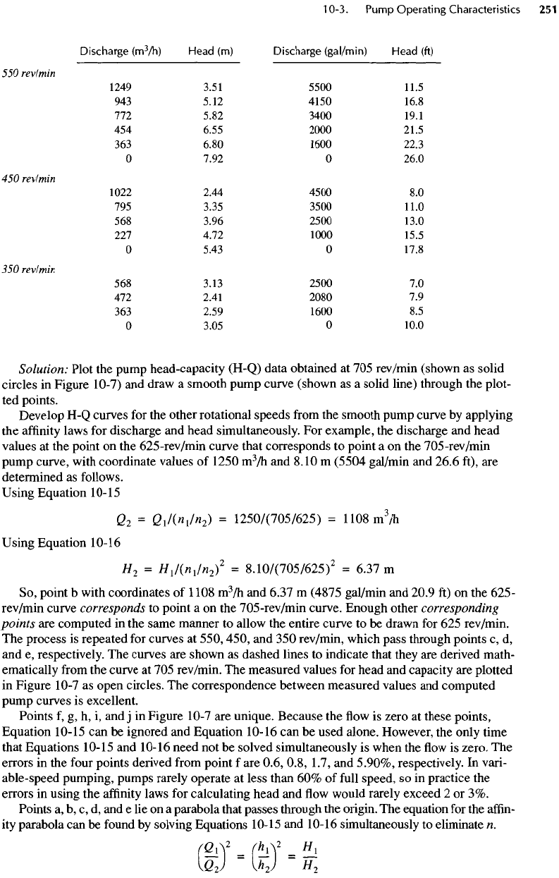
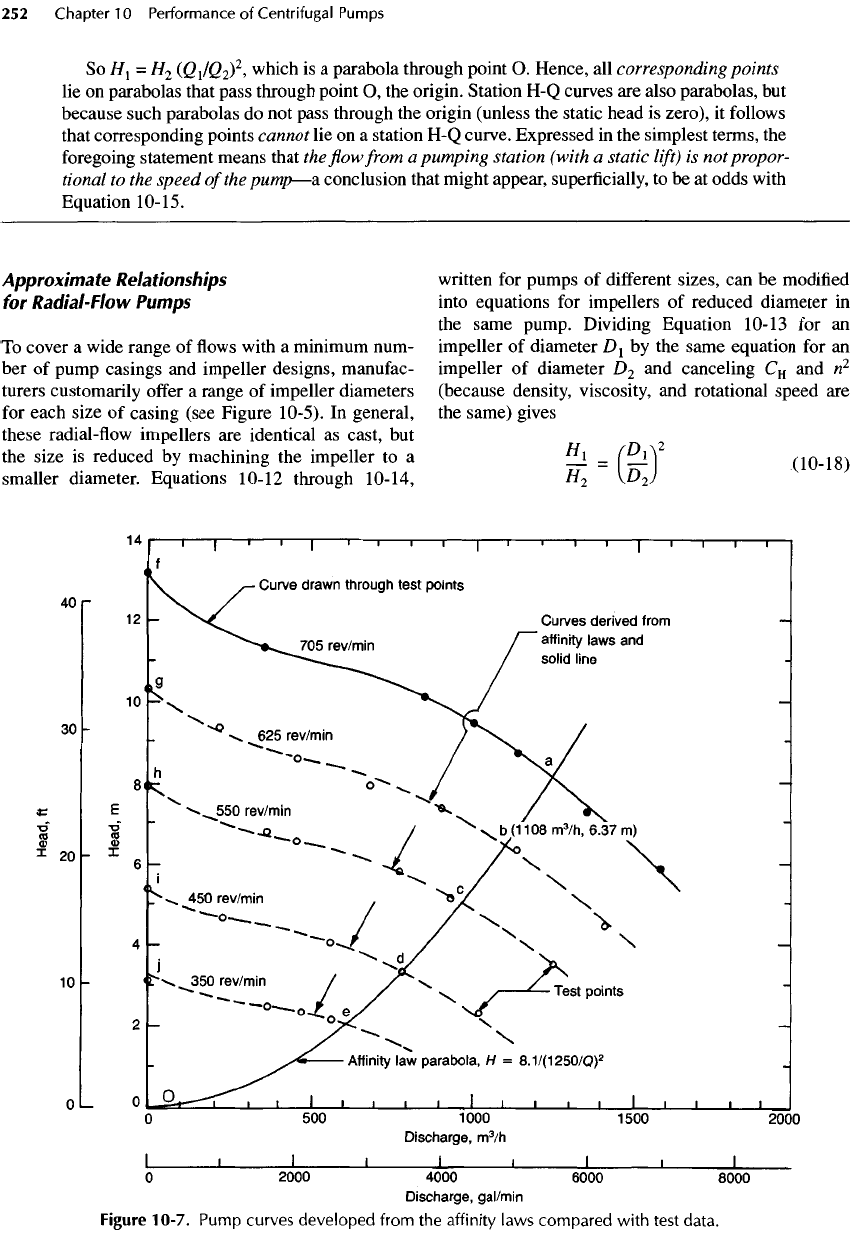
Solution: Plot
the
pump head-capacity (H-Q) data obtained
at 705
rev/min (shown
as
solid
circles
in
Figure
10-7)
and
draw
a
smooth pump curve (shown
as a
solid line) through
the
plot-
ted
points.
Develop
H-Q
curves
for the
other rotational
speeds
from
the
smooth pump curve
by
applying
the
affinity
laws
for
discharge
and
head simultaneously.
For
example,
the
discharge
and
head
values
at the
point
on the
625-rev/min
curve that corresponds
to
point
a on the
705-rev/min
pump
curve,
with
coordinate values
of
1250
m
3
/h
and
8.10
m
(5504
gal/min
and
26.6 ft),
are
determined
as
follows.
Using Equation
10-15
Q
2
=
Q
1
Kn
1
In
2
)
=
1250/(705/625)
=
1108
m
3
/h
Using Equation
10-16
H
2
=
H
1
Kn
1
In
2
)
2
=
8.10/(705/625)
2
=
6.37
m
So,
point
b
with coordinates
of
1108
m
3
/h
and
6.37
m
(4875 gal/min
and
20.9
ft) on the
625-
rev/min curve
corresponds
to
point
a on the
705-rev/min
curve. Enough other
corresponding
points
are
computed
in the
same manner
to
allow
the
entire curve
to be
drawn
for 625
rev/min.
The
process
is
repeated
for
curves
at
550, 450,
and 350
rev/min, which pass through points
c, d,
and
e,
respectively.
The
curves
are
shown
as
dashed lines
to
indicate that they
are
derived math-
ematically
from
the
curve
at 705
rev/min.
The
measured values
for
head
and
capacity
are
plotted
in
Figure 10-7
as
open
circles.
The
correspondence between measured values
and
computed
pump
curves
is
excellent.
Points
f, g, h, i, and j in
Figure 10-7
are
unique. Because
the flow is
zero
at
these points,
Equation
10-15
can be
ignored
and
Equation 10-16
can be
used alone. However,
the
only time
that
Equations
10-15
and
10-16
need
not be
solved simultaneously
is
when
the flow is
zero.
The
errors
in the
four
points derived
from
point
f are
0.6, 0.8,
1.7,
and
5.90%, respectively.
In
vari-
able-speed pumping, pumps rarely operate
at
less than
60% of
full
speed,
so in
practice
the
errors
in
using
the
affinity
laws
for
calculating head
and flow
would rarely exceed
2 or
3%.
Points
a, b, c, d, and e lie on a
parabola that passes through
the
origin.
The
equation
for the
affin-
ity
parabola
can be
found
by
solving Equations
10-15
and
10-16
simultaneously
to
eliminate
n.
(GA
2
=
(AA
2
=
^l
(Q
2
)
U
2
J
H
2
Approximate
Relationships
for
Radial-Flow
Pumps
To
cover
a
wide range
of flows
with
a
minimum num-
ber of
pump casings
and
impeller designs, manufac-
turers customarily
offer
a
range
of
impeller diameters
for
each size
of
casing (see Figure 10-5).
In
general,
these radial-flow impellers
are
identical
as
cast,
but
the
size
is
reduced
by
machining
the
impeller
to a
smaller diameter. Equations 10-12 through
10-14,
written
for
pumps
of
different
sizes,
can be
modified
into equations
for
impellers
of
reduced diameter
in
the
same pump. Dividing Equation 10-13
for an
impeller
of
diameter
D
1
by the
same equation
for an
impeller
of
diameter
D
2
and
canceling
C
H
and n
2
(because density, viscosity,
and
rotational speed
are
the
same) gives
g
-
©'
So
H
1
=
H
2
(Q\IQ'ii
L
,
which
is a
parabola through point
O.
Hence,
all
corresponding
points
lie on
parabolas that pass through point
O, the
origin. Station
H-Q
curves
are
also parabolas,
but
because such parabolas
do not
pass through
the
origin (unless
the
static head
is
zero),
it
follows
that
corresponding points cannot
lie on a
station
H-Q
curve. Expressed
in the
simplest terms,
the
foregoing
statement means that
the flow
from
a
pumping station
(with
a
static
lift)
is not
propor-
tional
to the
speed
of
the
pump—a
conclusion that might appear, superficially,
to be at
odds with
Equation
10-15.
Figure
10-7. Pump curves
developed
from
the
affinity laws
compared
with
test
data.
