Pumping Station Desing - Second Edition by Robert L. Sanks, George Tchobahoglous, Garr M. Jones
Подождите немного. Документ загружается.

pump
to the
lead position (with manual lead/follow selector)
to
clear
the
alarm.
The
problem
with
the
lead pump
can
usually
be
corrected
by the
operator immediately.
For a
discharge
of 300
gal/min,
the
velocity
(from
Table B-4)
in a
6-in.-diameter
steel pipe,
unlined
or
lined with plastic
or
coal tar, would
be
5(300/447)
= 3.4
ft/s, which
is
satisfactory.
(If
the
lining were cement-mortar,
the ID
would
be
less,
and the
velocity would
be 4.0
ft/s—which
is
also satisfactory.)
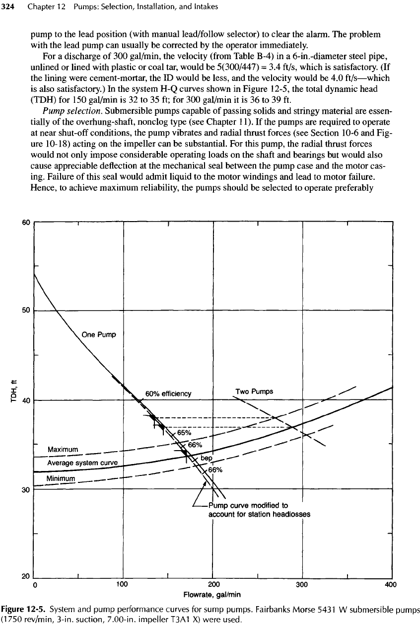
In the
system
H-Q
curves shown
in
Figure 12-5,
the
total dynamic head
(TDH)
for
150
gal/min
is 32 to 35 ft; for 300
gal/min
it is 36 to 39 ft.
Pump
selection. Submersible pumps capable
of
passing solids
and
stringy material
are
essen-
tially
of the
overhung-shaft,
nonclog type (see Chapter
11).
If the
pumps
are
required
to
operate
at
near
shut-off
conditions,
the
pump vibrates
and
radial thrust forces (see Section 10-6
and
Fig-
ure
10-18)
acting
on the
impeller
can be
substantial.
For
this pump,
the
radial thrust forces
would
not
only impose considerable operating loads
on the
shaft
and
bearings
but
would also
cause appreciable deflection
at the
mechanical seal between
the
pump case
and the
motor cas-
ing. Failure
of
this seal would admit liquid
to the
motor windings
and
lead
to
motor failure.
Hence,
to
achieve maximum reliability,
the
pumps should
be
selected
to
operate preferably
Figure
12-5.
System
and
pump
performance curves
for
sump pumps. Fairbanks Morse 5431
W
submersible pumps
(1
750
rev/min,
3-in.
suction,
7.00-in.
impeller
T3A1
X)
were used.
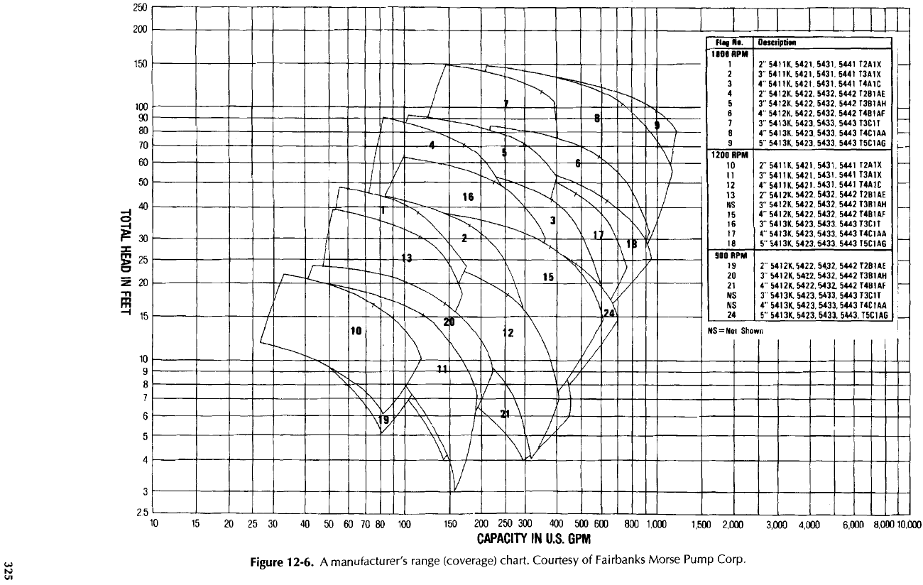
Figure 12-6.
A
manufacturer's range (coverage) chart. Courtesy
of
Fairbanks
Morse Pump Corp.
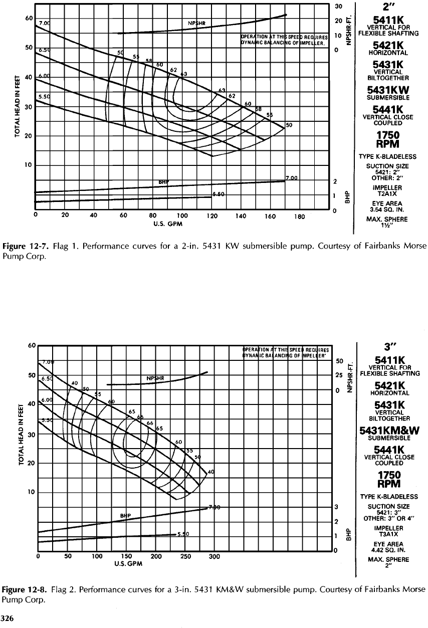
Figure
12-7.
Flag
1.
Performance curves
for a
2-in. 5431
KW
submersible
pump.
Courtesy
of
Fairbanks
Morse
Pump Corp.
Figure
12-8. Flag
2.
Performance curves
for a
3-in.
5431
KM&W
submersible
pump.
Courtesy
of
Fairbanks Morse
Pump
Corp.
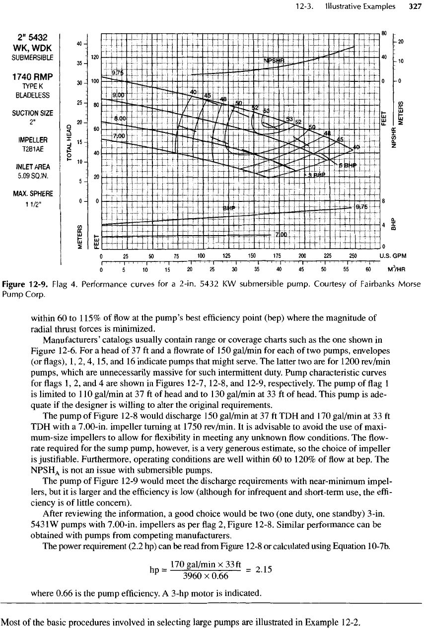
Figure
12-9. Flag
4.
Performance curves
for a
2-in.
5432
KW
submersible
pump.
Courtesy
of
Fairbanks
Morse
Pump
Corp.
within
60 to
115%
of flow at the
pump's
best
efficiency
point (bep) where
the
magnitude
of
radial thrust forces
is
minimized.
Manufacturers'
catalogs usually contain range
or
coverage charts such
as the one
shown
in
Figure
12-6.
For a
head
of 37 ft and a flowrate of 150
gal/min
for
each
of two
pumps, envelopes
(or
flags),
1,2,4,
15, and 16
indicate pumps that might serve.
The
latter
two are for
1200
rev/min
pumps,
which
are
unnecessarily massive
for
such intermittent duty. Pump
characteristic
curves
for
flags
1,
2, and 4 are
shown
in
Figures 12-7, 12-8,
and
12-9, respectively.
The
pump
of flag 1
is
limited
to
110
gal/min
at 37 ft of
head
and to 130
gal/min
at 33 ft of
head. This pump
is
ade-
quate
if the
designer
is
willing
to
alter
the
original requirements.
The
pump
of
Figure 12-8 would discharge
150
gal/min
at 37 ft TDH and 170
gal/min
at 33 ft
TDH
with
a
7.00-in.
impeller turning
at
1750 rev/min.
It is
advisable
to
avoid
the use of
maxi-
mum-size
impellers
to
allow
for flexibility in
meeting
any
unknown
flow
conditions.
The flow-
rate required
for the
sump pump, however,
is a
very generous estimate,
so the
choice
of
impeller
is
justifiable.
Furthermore, operating conditions
are
well within
60 to
120%
of flow at
bep.
The
NPSH
A
is not an
issue with submersible pumps.
The
pump
of
Figure
12-9
would meet
the
discharge requirements with near-minimum impel-
lers,
but it is
larger
and the
efficiency
is low
(although
for
infrequent
and
short-term use,
the
effi-
ciency
is of
little concern).
After
reviewing
the
information,
a
good choice would
be two
(one
duty,
one
standby)
3-in.
543IW
pumps with
7.00-in.
impellers
as per flag 2,
Figure 12-8. Similar performance
can be
obtained with pumps
from
competing manufacturers.
The
power requirement (2.2
hp) can be
read
from
Figure
12-8
or
calculated using Equation 10-7b.
,
170
gal/min
x
33ft
0
1
.
hp=
3960X0.66
=2
'
15
where
0.66
is the
pump
efficiency.
A
3-hp motor
is
indicated.
Most
of the
basic procedures involved
in
selecting large pumps
are
illustrated
in
Example
12-2.
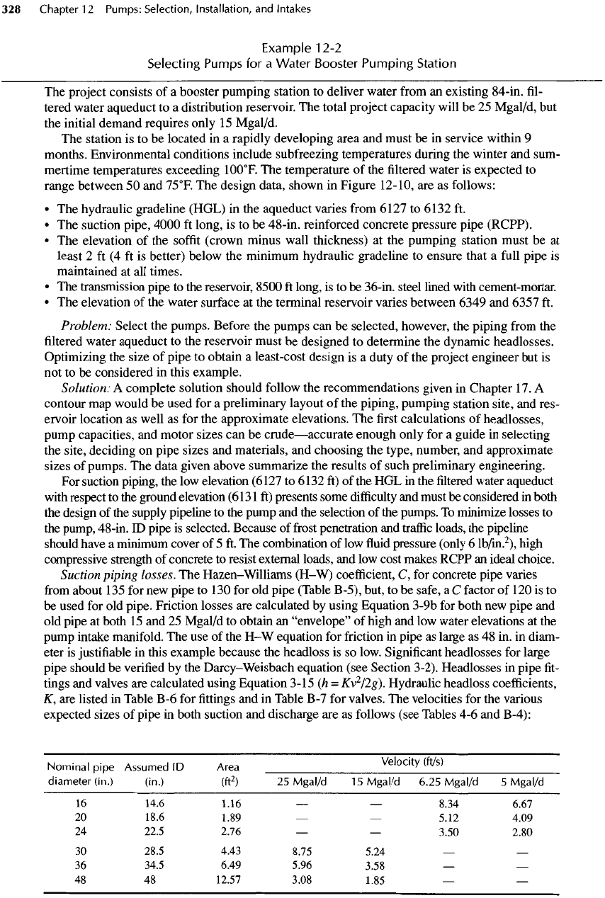
Example
12-2
Selecting
Pumps
for a
Water Booster Pumping Station
The
project consists
of a
booster pumping station
to
deliver water
from
an
existing 84-in.
fil-
tered water aqueduct
to a
distribution reservoir.
The
total project capacity will
be 25
Mgal/d,
but
the
initial demand requires only
15
Mgal/d.
The
station
is to be
located
in a
rapidly developing area
and
must
be in
service within
9
months. Environmental
conditions
include subfreezing temperatures during
the
winter
and
sum-
mertime temperatures exceeding
10O
0
F.
The
temperature
of the filtered
water
is
expected
to
range
between
50 and
75
0
F.
The
design data, shown
in
Figure
12-10,
are as
follows:
• The
hydraulic gradeline (HGL)
in the
aqueduct varies
from
6121
to
6132
ft.
• The
suction pipe,
4000
ft
long,
is to be
48-in. reinforced concrete pressure pipe (RCPP).
• The
elevation
of the
soffit
(crown minus wall thickness)
at the
pumping station must
be at
least
2 ft (4 ft is
better)
below
the
minimum hydraulic
gradeline
to
ensure that
a
full
pipe
is
maintained
at all
times.
• The
transmission pipe
to the
reservoir,
8500
ft
long,
is to be
36-in.
steel lined with cement-mortar.
• The
elevation
of the
water surface
at the
terminal reservoir varies between 6349
and
6357
ft.
Problem: Select
the
pumps. Before
the
pumps
can be
selected, however,
the
piping
from
the
filtered
water
aqueduct
to the
reservoir must
be
designed
to
determine
the
dynamic headlosses.
Optimizing
the
size
of
pipe
to
obtain
a
least-cost design
is a
duty
of the
project engineer
but is
not
to be
considered
in
this example.
Solution:
A
complete solution should follow
the
recommendations given
in
Chapter
17.
A
contour
map
would
be
used
for a
preliminary layout
of the
piping, pumping station site,
and
res-
ervoir location
as
well
as for the
approximate elevations.
The first
calculations
of
headlosses,
pump
capacities,
and
motor sizes
can be
crude—accurate
enough only
for a
guide
in
selecting
the
site, deciding
on
pipe sizes
and
materials,
and
choosing
the
type, number,
and
approximate
sizes
of
pumps.
The
data given above summarize
the
results
of
such preliminary engineering.
For
suction piping,
the low
elevation (6127
to
6132
ft) of the HGL in the filtered
water aqueduct
with
respect
to the
ground elevation
(6131
ft)
presents some
difficulty
and
must
be
considered
in
both
the
design
of the
supply pipeline
to the
pump
and the
selection
of the
pumps.
To
minimize losses
to
the
pump, 48-in.
ID
pipe
is
selected. Because
of frost
penetration
and
traffic
loads,
the
pipeline
should
have
a
minimum cover
of 5 ft. The
combination
of low fluid
pressure (only
6
lb/in.
2
),
high
compressive strength
of
concrete
to
resist external loads,
and low
cost makes RCPP
an
ideal choice.
Suction
piping losses.
The
Hazen-Williams
(H-W)
coefficient,
C, for
concrete
pipe
varies
from
about
135 for new
pipe
to
130
for old
pipe (Table B-5), but,
to be
safe,
a C
factor
of 120 is to
be
used
for old
pipe.
Friction
losses
are
calculated
by
using Equation
3-9b
for
both
new
pipe
and
old
pipe
at
both
15 and 25
Mgal/d
to
obtain
an
"envelope"
of
high
and low
water elevations
at the
pump
intake manifold.
The use of the H-W
equation
for
friction
in
pipe
as
large
as 48 in. in
diam-
eter
is
justifiable
in
this example because
the
headloss
is so
low. Significant headlosses
for
large
pipe should
be
verified
by the
Darcy-Weisbach equation
(see
Section 3-2). Headlosses
in
pipe
fit-
tings
and
valves
are
calculated using Equation
3-15
(h =
Kv
2
/2g).
Hydraulic headloss coefficients,
K,
are
listed
in
Table
B-6
for fittings and in
Table
B-7
for
valves.
The
velocities
for the
various
expected sizes
of
pipe
in
both suction
and
discharge
are as
follows (see Tables
4-6 and
B-4):
Nominal
pipe
Assumed
ID
A?!Velocity
(ft/s)
diameter
(in.)
(in.)
(ft
2
)
25
Mgal/d
15
Mgal/d 6.25 Mgal/d
5
Mgal/d
16
14.6 1.16
— —
8.34 6.67
20
18.6 1.89
— —
5.12 4.09
24
22.5 2.76
— —
3.50 2.80
30
28.5 4.43 8.75 5.24
— —
36
34.5 6.49 5.96 3.58
— —
48
48
12.57 3.08 1.85
— —
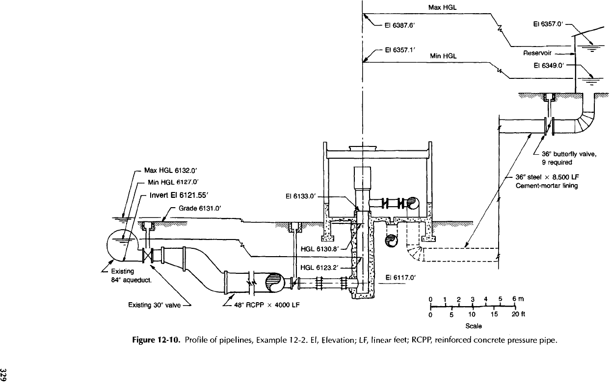
Figure
12-10.
Profile
of
pipelines,
Example
12-2.
El,
Elevation;
LF,
linear feet;
RCPP,
reinforced concrete
pressure
pipe.
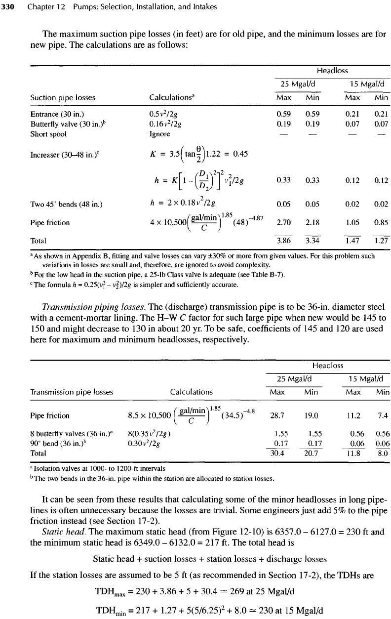
The
maximum suction pipe losses
(in
feet)
are for old
pipe,
and the
minimum losses
are for
new
pipe.
The
calculations
are as
follows:
Headless
25
Mgal/d
15
Mgal/d
Suction
pipe
losses
Calculations
3
Max Min Max Min
Entrance
(30
in.)
0.5v
2
/2g
0.59 0.59 0.21 0.21
Butterfly
valve
(30
in.)
b
0.16v
2
/2#
0.19 0.19 0.07 0.07
Short
spool Ignore
— — — —
Increaser
(30-48
in.)
c
K =
3.5ftan^l.22
=
0.45
r
fD
}
\2-a
2
h
= K 1-
—-
V2g
0.33 0.33 0.12 0.12
Two
45°
bends
(48
in.)
h = 2 x
0.18v
/2g
0.05 0.05 0.02 0.02
Pipe
friction
4 X
10,500(%
al/
™
m
}
'
(48)~
4
-
87
2.70 2.18 1.05 0.85
\
*-•
/
Total
3.86
^334
1.47 1.27
a
As
shown
in
Appendix
B,
fitting
and
valve
losses
can
vary
±30%
or
more
from
given
values.
For
this
problem
such
variations
in
losses
are
small
and,
therefore,
are
ignored
to
avoid
complexity.
b
For the
low
head
in the
suction
pipe,
a
25-lb
Class
valve
is
adequate (see
Table
B-7).
c
The
formula
h =
0.25(vf
-
vfyflg
is
simpler
and
sufficiently
accurate.
Transmission
piping losses.
The
(discharge) transmission pipe
is to be
36-in.
diameter steel
with
a
cement-mortar lining.
The H-W C
factor
for
such large pipe when
new
would
be
145
to
150
and
might decrease
to
130
in
about
20 yr. To be
safe, coefficients
of 145 and 120 are
used
here
for
maximum
and
minimum headlosses, respectively.
Headless
25
Mgal/d
15
Mgal/d
Transmission
pipe
losses
Calculations
Max Min Max Min
Pipe
friction
8.5 x
10,500
(%*
l/
™
in
}
'
(34.5)"
4
'
8
28.7 19.0 11.2
7.4
8
butterfly
valves
(36
in.)
a
8(0.35v
2
/2g)
1.55 1.55 0.56 0.56
90°
bend
(36
in.)
b
0.30v
2
/2g
0.17
0.17
0.06
0.06
Total
30.4 20.7 11.8
8.0
isolation
valves
at
1000-
to
1200-ft
intervals
b
The
two
bends
in the
36-in.
pipe
within
the
station
are
allocated
to
station
losses.
It can be
seen
from
these results that calculating some
of the
minor headlosses
in
long pipe-
lines
is
often
unnecessary because
the
losses
are
trivial. Some engineers just
add 5% to the
pipe
friction
instead (see Section 17-2).
Static
head.
The
maximum static head
(from
Figure
12-10)
is
6357.0
-
6127.0
= 230 ft and
the
minimum static head
is
6349.0
-
6132.0
= 217 ft. The
total head
is
Static
head
+
suction losses
+
station losses
+
discharge losses
If
the
station losses
are
assumed
to be 5 ft (as
recommended
in
Section 17-2),
the
TDHs
are
TDH
max
=
230 +
3.86
+ 5 +
30.4
-
269 at 25
Mgal/d
TDH
min
= 217 +
1.27
+
5(5/6.25)
2
+ 8.0
-
230 at 15
Mgal/d
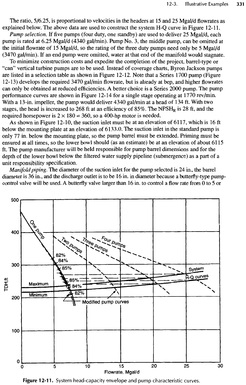
The
ratio,
5/6.25,
is
proportional
to
velocities
in the
headers
at 15 and 25
Mgal/d
flowrates as
explained below.
The
above data
are
used
to
construct
the
system
H-Q
curve
in
Figure
12-11.
Pump
selection.
If five
pumps
(four
duty,
one
standby)
are
used
to
deliver
25
Mgal/d, each
pump
is
rated
at
6.25 Mgal/d (4340
gal/min).
Pump
No. 3, the
middle pump,
can be
omitted
at
the
initial
flowrate of 15
Mgal/d,
so the
rating
of the
three
duty
pumps need only
be 5
Mgal/d
(3470 gal/min).
If an end
pump were omitted, water
at
that
end of the
manifold would stagnate.
To
minimize construction costs
and
expedite
the
completion
of the
project, barrel-type
or
"can" vertical turbine pumps
are to be
used. Instead
of
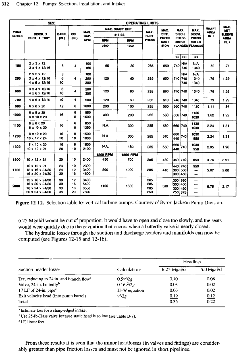
coverage charts, Byron Jackson pumps
are
listed
in a
selection table
as
shown
in
Figure
12-12.
Note that
a
Series 1700 pump (Figure
12-13)
develops
the
required 3470 gal/min
flowrate, but is
already
at
bep,
and
higher
flowrates
can
only
be
obtained
at
reduced
efficiencies.
A
better choice
is a
Series
2000
pump.
The
pump
performance
curves
are
shown
in
Figure
12-14
for a
single stage operating
at
1770
rev/min.
With
a
13-in.
impeller,
the
pump would deliver
4340
gal/min
at a
head
of
134
ft.
With
two
stages,
the
head
is
increased
to 268 ft at an
efficiency
of
85%.
The
NPSH
R
is 28 ft, and the
required horsepower
is 2 x 180 =
360,
so a
400-hp motor
is
needed.
As
shown
in
Figure
12-10,
the
suction inlet must
be at an
elevation
of
6117,
which
is
16
ft
below
the
mounting plate
at an
elevation
of
6133.0.
The
suction inlet
in the
standard pump
is
only
77 in.
below
the
mounting plate,
so the
pump barrel must
be
extended. Priming must
be
ensured
at all
times,
so the
lower bowl should
(as an
estimate)
be at an
elevation
of
about
6115
ft.
The
pump manufacturer will
be
held responsible
for
pump barrel dimensions
and for the
depth
of the
lower bowl below
the filtered
water supply pipeline (submergence)
as a
part
of a
unit
responsibility specification.
Manifold
piping.
The
diameter
of the
suction inlet
for the
pump selected
is 24
in.,
the
barrel
diameter
is 36
in.,
and the
discharge outlet
is to be 16 in. in
diameter because
a
butterfly-type
pump-
control valve will
be
used.
A
butterfly
valve larger than
16 in. to
control
a flow
rate
from
O to 5 or
Figure
12-11.
System head-capacity
envelope
and
pump
characteristic curves.
SB
SH
SH
"^"
i:ii$
H
~~~%
-
°°
28s
~^™^
,%
-*~~
2 x 3 x 12 8 100 N/A N/A
200
3x4x12/16
8 4 200 120 60 285 650
740740
1340
.79
1.29
4
x 6 x
12/16
10 300 740
1340
600
4x6x12n6
10
4
HO
12
°
6
°
285
66
°
74
°
74
°
134
°
79
1
'
29
700
4x6x12/16
10 4 600 120 60 285 610 740 740
1340
.79
1.29
800
6x8x20
12 6
1000
200 100 285 560
660740
1130 1.11
.97
"^"
;;?.'£*i~~£
™ ™
"
2as
«
~™"™r
i*
^
"°°
XvS
0
16
8
lS
"•*•
30
O
580
660740
^
2.24
1.31
»0°
,;;;;;»
^
0
6
,;
™
NA
aoo
285
570
%>
™
2
.
24
„,
"°°
,;;i.°.'g
2
io
8
as
*•*•
«•
-
s
*°
s»°
1
Sg
«•»
i*
1200
RPM
1800
RPM
1500
10x12x24
20 10
2400
450 700 285 430
440740
950
3.76 3.91
10
x 12 x 24 24 10
2300
440 740 950
1700
12 x 16 x
24/30
24 12
3400
800
1200
285 410 300 560 —
5.67 2.00
16
x 20 x
24/30
30 16
4600
300 450 —
12
x 16 x
24/30
30 12
3400
285 300 560 —
16
x
20x24/30
30 16
5400
285
300450
-
2000
16x24x24/30
30 16
6500
11
°°
16
°°
285
56
°
300450
-
6
'
78
2
'
17
20 x 24 x
24/30
36 20
7800
250 250 375 —
Figure
12-12.
Selection table
for
vertical
turbine
pumps. Courtesy
of
Byron
Jackson
Pump
Division.
6.25
Mgal/d
would
be out of
proportion;
it
would have
to
open
and
close
too
slowly,
and the
seats
would
wear quickly
due to the
cavitation that occurs when
a
butterfly
valve
is
nearly closed.
The
hydraulic losses through
the
suction
and
discharge headers
and
manifolds
can now be
computed (see Figures
12-15
and
12-16).
Headless
Suction
header
losses
Calculations 6.25
Mgal/d
5.0
Mgal/d
Tee, reducing
to 24 in. and
branch
flow
a
0.5v
2
/2g
0.10
0.06
Valve,
24-in.
butterfly
5
0.16v
2
/2g
0.03 0.02
17LFof24-in.pipe
c
H-W
equation 0.03 0.02
Exit
velocity head (into pump barrel)
v
2
/2g
0.19 0.12
Total
0.35 0.22
a
Estimate
loss
for a
sharp-edged intake.
b
Use
25-lb
Class
valve
because
static
head
is so low
(see Table
B-7).
c
LF,
linear
feet.
From these results
it is
seen that
the
minor headlosses
(in
valves
and fittings) are
consider-
ably
greater than pipe friction losses
and
must
not be
ignored
in
short pipelines.
SIZE
PUMP
SERIES
DISCH.
X
SUCT.
X
"BD"
BARR.
(IN.)
COL.
(IN.)
MAX.
CAP.
GPM
OPERATING
LIMITS
MAX.
SHAFT
BHP
416SS
RPM
3600
RPM
1800
MAX.
SUCT.
PRESS
MAX.
DIFF.
PRESS
CAST
IRON
MAX.
DISCH.
PRESS
300
LB
FLANGES
MAX.
DISCH.
PRESS
600
LB
FLANGES
SHAFT
AREA
IN.
*
MAX.
NET
SLEEVE
AREA
IN. 2
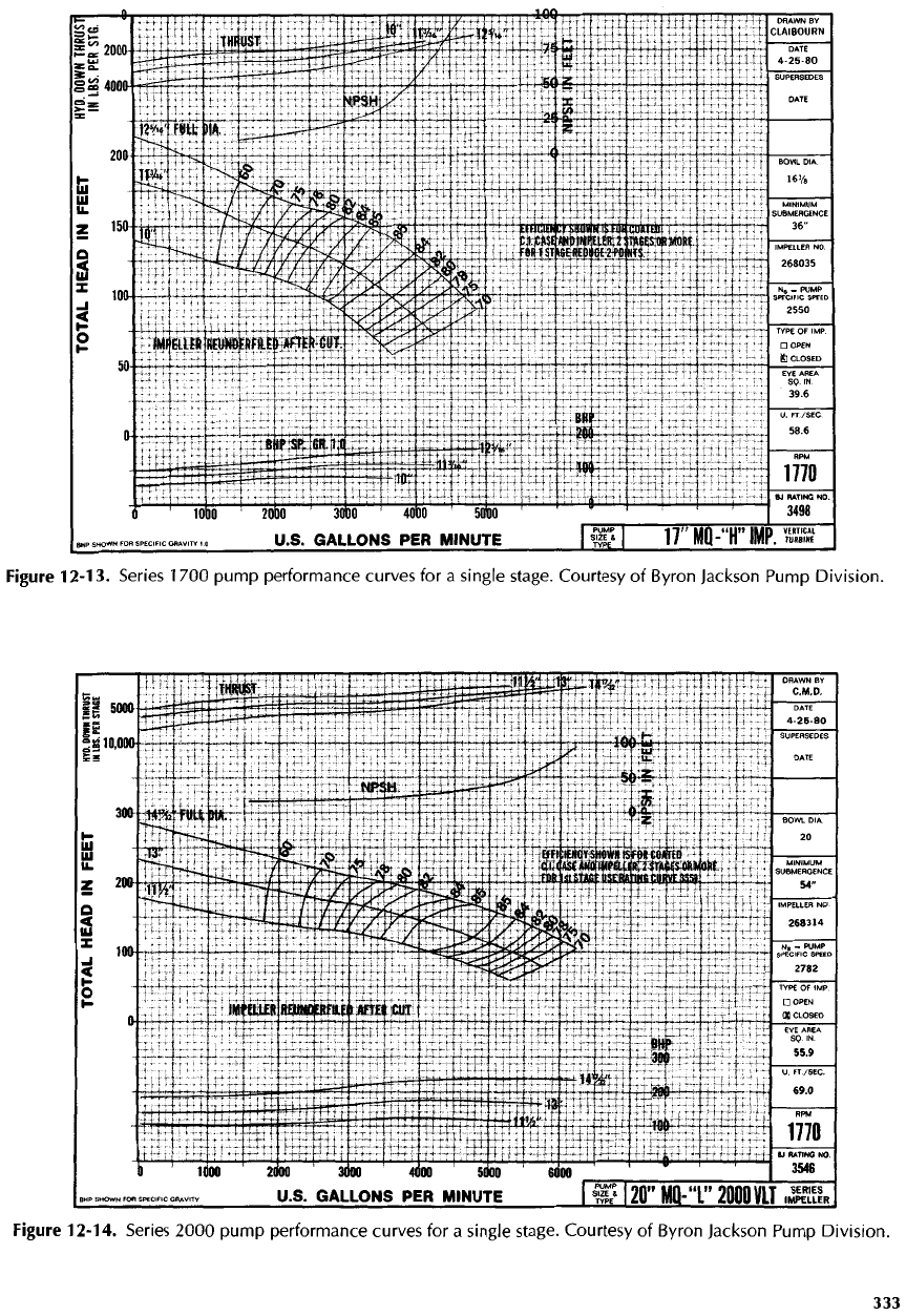
Figure
12-13.
Series
1700
pump
performance curves
for a
single stage. Courtesy
of
Byron
Jackson
Pump
Division.
Figure
12-14.
Series
2000
pump
performance curves
for a
single stage. Courtesy
of
Byron
Jackson
Pump
Division.
