Pumping Station Desing - Second Edition by Robert L. Sanks, George Tchobahoglous, Garr M. Jones
Подождите немного. Документ загружается.

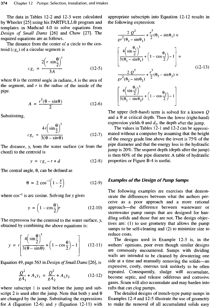
The
data
in
Tables
12-2
and
12-3
were calculated
by
Wheeler
[25]
using
his
PARTFULL® program
and
templates
in
Mathcad
4.0 to
solve equations
from
Design
of
Small Dams
[26]
and
Chow
[27].
The
required equations
are as
follows.
The
distance
from
the
center
of a
circle
to the
cen-
troid
(cg
c
)
of a
circular segment
is
2(r
S1
n§)
3
c
Sc
=
3A
(12-5)
where
0 is the
central angle
in
radians,
A is the
area
of
the
segment,
and r is the
radius
of the
inside
of the
pipe.
A
-
^
e
-
sin0
)
(12-6)
Substituting,
A
( •
0
V
4rl
sin-
I
«<
=
3(9
-sine)
^
The
distance,
y,
from
the
water
surface
(or
from
the
chord)
to the
centroid
is
y
=
cg
c
-r
+ d
(12-8)
The
central angle,
0, can be
defined
as
0 =
2cos~
1
fl-^
(12-9)
V
r)
where
cos"
1
is arc
cosine. Solving
for
_y
gives
y
=
fl-cos^lr
(12-10)
The
expression
for the
centroid
to the
water surface,
y,
obtained
by
combining
the
above equations
is:
I"
4
KT
1
>
=
'
3(6
-
sine)
+
('-
"
08
I)-
1
(ml)
Equation
49,
page
563 in
Design
of
Small
Dams
[26],
is
12L
+
A
1
J
1
=
^
+
A
2
J
2
(12-12)
where subscript
1 is
used before
the
jump
and
sub-
script
2 is
used
after
the
jump. Note that both
y and 0
are
changed
by the
jump. Substituting
the
expressions
for
A
(Equation
12-6)
and y
(Equation
12-11)
with
appropriate
subscripts into Equation
12-12
results
in
the
following expression:
2
2Q
+
j(®i
~
sine,)
X
Sr(O
1
-SiIIe
1
)
2
r
(
6
A
3
i
4
sin
Tj
(
BA
3(
e
1
-s
1
ne
l)
H
1
-
cos
2j-
1
=
2
(12-13)
9
n
2
r
2
*
+
T
(e
2
-
sine
2
)
x
gr
(O
2
-SmG
2
)
z
r
(
®2\
3
i
4
i
sin
yJ
( 0
3(O
1
-sin0
2
)
H
1
-^2
2
J-
1
The
upper
(left-hand)
term
is
solved
for a
known
Q
and
a 0 at
critical depth. Then
the
lower (right-hand)
expression yields
0 and
J
2
,
the
depth
after
the
jump.
The
values
in
Tables
12-1
and
12-2
can be
approxi-
mated without
a
computer
by
assuming that
the
height
of
the
energy grade line above
the
invert
is 75% of the
pipe
diameter
and
that
the
energy
loss
in the
hydraulic
jump
is
20%.
The
sequent depth (depth
after
the
jump)
is
then
60% of the
pipe diameter.
A
table
of
hydraulic
properties
or
Figure
B
-4
is
useful.
Examples
of the
Design
of
Pump
Sumps
The
following examples
are
exercises that demon-
strate
the
differences between what
the
authors
per-
ceive
as a
poor approach
and a
more rational
approach
—
the
difference between wastewater
or
stormwater
pump sumps that
are
designed
for
han-
dling solids
and
those that
are
not.
The
design objec-
tives
are:
(1) to use
geometry that allows
the
pump
sumps
to be
self-cleaning
and (2) to
minimize size
to
reduce costs.
The
designs used
in
Example
12-3
is, in the
authors' opinions, poor even though similar designs
are
commonly encountered. Sumps with dividing
walls
are
intended
to be
cleaned
by
dewatering
one
side
at a
time
and
manually removing
the
solids
—
an
expensive, costly, onerous task unlikely
to be
often
repeated. Consequently, sludge will accumulate,
become septic,
and
release
odiferous
and
corrosive
gases. Scum will also accumulate
and may
harden into
rafts
that
can
clog pumps.
The
detailed designs
of
trench-type pump sumps
in
Examples
12-4
and
12-5
illustrate
the use of
geometry
to
make
the
removal
of all
accumulated solids easy
and
quick
and to
provide good hydraulic conditions
for
the
pump suction intakes.
The
presentation
is
detailed
and,
consequently, tedious,
but
nevertheless,
first-time
readers
(even experienced engineers)
are
cautioned
to
follow
the
calculations
step
by
step
to
avoid
confusion.
An
expert,
who
develops short-cuts
and
puts most
of the
calculations
in
tabular form,
can
design
and
detail
an
ordinary trench-type pump sump
for
variable-speed pumps
in
about half
a
day,
even
without
a
computer. Although
the
design
of
pump
sumps
for
constant-
speed
pumps takes longer,
the
time required
is
certainly reasonable
and not a
deter-
rent.
Do
make
sufficient,
clearly understandable
cal-
culations
and
design notes
to
justify
all
important
design features, because they
are
needed
by
reviewers,
are filed in the
company archives,
and may be
needed
in
court
(see
Section
17-1).
Example
12-3
Design
of
Typical
Pumping
Station
Wet
Well
for C/S
Wastewater
Pumps
The
pump sump
for a C/S
pumping station
is to be
rectangular with
a
modified V-shaped bottom
and
fed
from
a
double channel with
a
comminutor
in one
side
and a
manually cleaned
bar
screen
in
the
other side. Plans
are
shown
in
Parts
B-4
and H of
this example.
A.
Design Conditions
1.
g
max
=
220 L/s (5
Mgal/d).
g
min
=
35 L/s
(0.8
Mgal/d).
2.
Typical
wet
pit-dry
pit
rectangular configuration.
3.
Use
three duty
+ one
standby pump, each
at
73.3
L/s
(1165
gal/min),
three
x
73.3
= 220
L/s.
If
friction headloss
is
significant,
a
single operating pump would
be
subject
to
less
head
and
would discharge more than
73.3 L/s.
4.
Pumps: horizontal with horizontal motors.
5.
Maximum water level change
= 1.2 m (4
ft).
6.
Frequency
of
motor starts
= 6/h
maximum
= 600
seconds between starts.
7.
Include comminutor
and bar
screen.
B.
Size
and
Shape
of
Sump
1.
Active volume required.
See
Equation
12-3:
V =
Tq/4
V =
600x73.3/4
= 11
m
3
(388
ft
3
)
2.
Dimensions
of
sump.
See
Part
H for final
dimensions.
a. Set
pumps
1.8 m (6 ft) c-c for
maintenance access.
b.
Center
the
outboard pump intakes
0.3 m (1 ft)
from
the end of
sump.
c.
Length
of
sump
= (3 x
1.8)
+ (2 x
0.3)
= 6.0 m
(19.7
ft)
long.
d.
Make sump
2.5 m
(8.2
ft)
wide, because less width does
not
give enough room
for
sluice gate
in
dividing wall,
as
will
be
seen.
3.
Water levels
(see
Figure 12-42).
a.
HWL to be at
invert
of
inlet pipe,
El
6.22
m
(above mean
sea
level)
b.
Set
pump start
and
stop levels
150 mm (6
in.)
apart
so
that excessive sensitivity
in
switching
is not
required.
c.
Active depth (HWL
-
LWL
per
pump)
=
active volume/area sump.
11
m
3
/(6.0
m x 2.5 m) =
0.73
m
(2.4
ft);
e.g.,
Pump
2
start
to
stop elevation difference
=
0.73
m.
d.
Headloss
in
comminutor
=
0.10
m (4
in.)
from
manufacturer's literature.
e.
Establish
HWL at
inlet
pipe
invert
elevation—6.22
m.
Arbitrary (many engineers
worry
about deposition
in
sewer
if HWL is
above invert).
f.
Then
LWL in
sump
=
6.22
-
(0.10
+
0.150
x 2 +
0.73)
=
5.09
m.
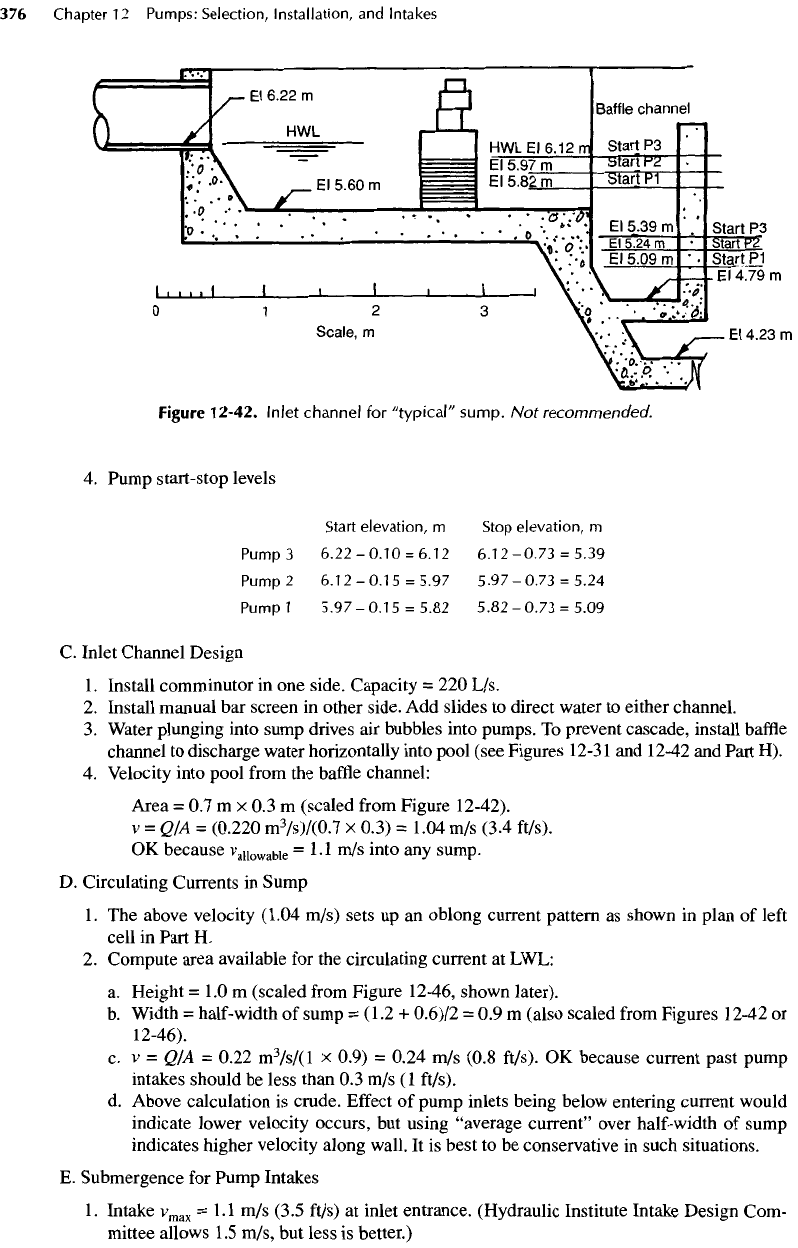
Figure
12-42.
Inlet
channel
for
"typical"
sump.
Not
recommended.
4.
Pump
start-stop
levels
Start
elevation,
m
Stop
elevation,
m
Pump
3
6.22-0.10
=
6.12
6.12-0.73
=
5.39
Pump
2
6.12-0.15
=
5.97
5.97-0.73
=
5.24
Pump
1
5.97
-
0.15
=
5.82 5.82
-
0.73
=
5.09
C.
Inlet Channel Design
1.
Install comminutor
in one
side. Capacity
= 220
L/s.
2.
Install manual
bar
screen
in
other side.
Add
slides
to
direct water
to
either channel.
3.
Water plunging into sump drives
air
bubbles into pumps.
To
prevent
cascade,
install
baffle
channel
to
discharge water horizontally into pool (see Figures 12-31
and
12-42
and
Part
H).
4.
Velocity into pool
from
the
baffle
channel:
Area
= 0.7 m x 0.3 m
(scaled
from
Figure 12-42).
v
=
Q/A
=
(0.220
m
3
/s)/(0.7
x
0.3)
=
1.04
m/s
(3.4
ft/s).
OK
because
v
allowable
=1.1
m/s
into
any
sump.
D.
Circulating Currents
in
Sump
1.
The
above velocity
(1.04
m/s) sets
up an
oblong current pattern
as
shown
in
plan
of
left
cell
in
Part
H.
2.
Compute area available
for the
circulating current
at
LWL:
a.
Height
= 1.0 m
(scaled
from
Figure
12-46,
shown later).
b.
Width
=
half-width
of
sump
=
(1.2
+
0.6)/2
= 0.9 m
(also scaled
from
Figures
12-42
or
12-46).
c. v = QIA =
0.22
m
3
/s/(l
x
0.9)
=
0.24
m/s
(0.8
ft/s).
OK
because current past pump
intakes should
be
less than
0.3 m/s (1
ft/s).
d.
Above calculation
is
crude.
Effect
of
pump inlets being below entering current would
indicate lower velocity occurs,
but
using
"average
current"
over half-width
of
sump
indicates higher velocity along wall.
It is
best
to be
conservative
in
such situations.
E.
Submergence
for
Pump Intakes
1.
Intake
v
max
=1.1
m/s
(3.5 ft/s)
at
inlet entrance. (Hydraulic Institute Intake Design Com-
mittee allows
1.5
m/s,
but
less
is
better.)
2.
Size
of
intake:
A =
QIv
=
(0.073
m
3
/s)/(l.l
m/s)
=
0.066
m
2
.
3.
Intake diameter:
D =
J4A/K
=
J4
x
0.066/Ti
=
0.30
m (12
in).
4.
Suction pipe size:
v
max
= 2.4 m/s (8
ft/s)
in
suction pipe. (Approved
by
Hydraulic Institute
Intake Design Committee.)
5.
Suction pipe area:
A = QIv =
(0.073
m
3
/s)/(2.4
m/s)
=
0.030
m
2
.
6.
Suction pipe diameter
=
«j4A/n
=
J4
x
0.030/7C
= 200 m (8
in).
7.
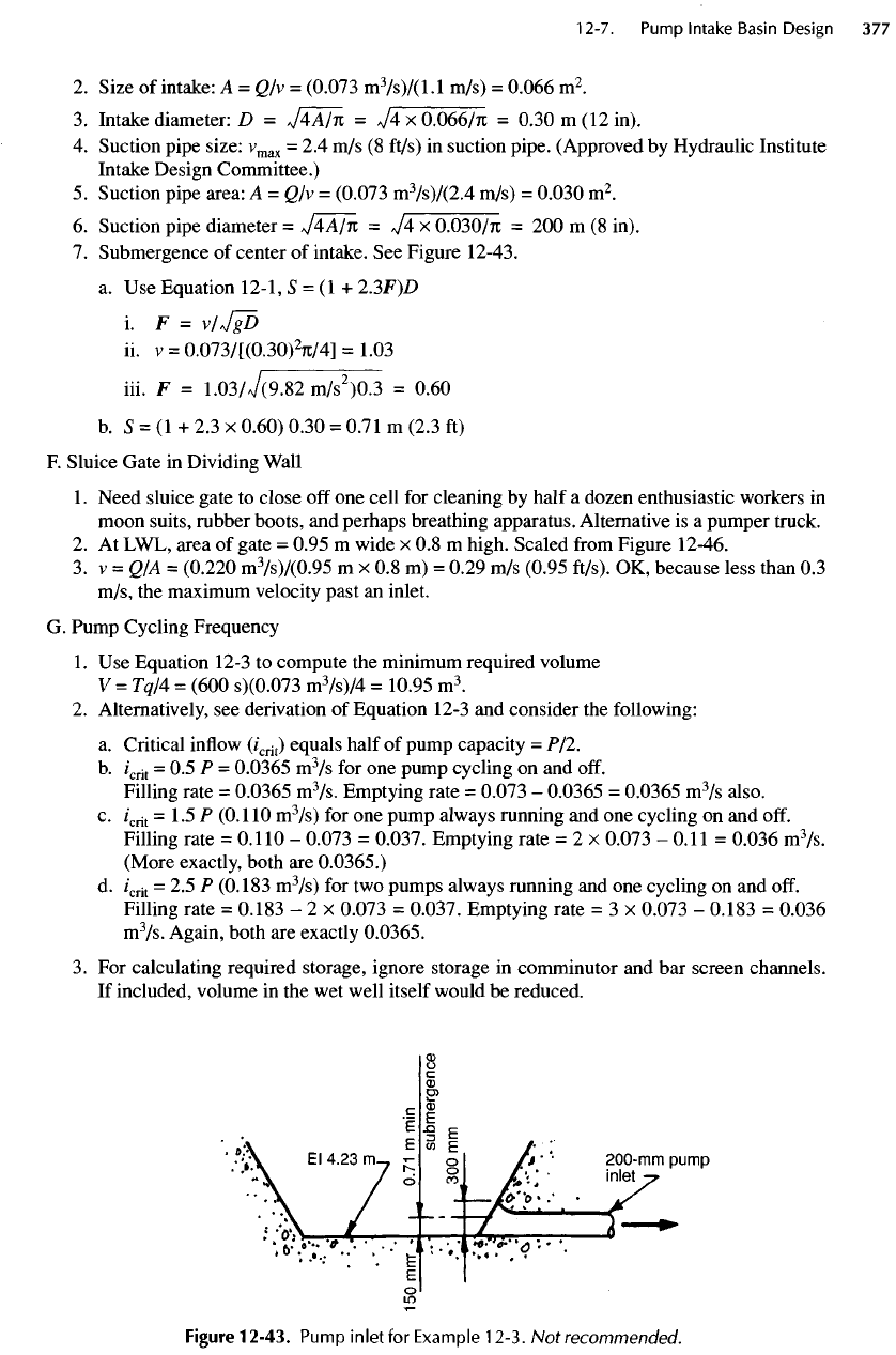
Submergence
of
center
of
intake.
See
Figure 12-43.
a. Use
Equation 12-1,
S = (1 +
2.3F)D
LF
=
v/JgD
ii. v =
0.073/[(0.30)
2
7i/4]
=
1.03
iii.
F =
1.03/7(9.82
m/s
2
)0.3
=
0.60
b.
S = (1 + 2.3 x
0.60) 0.30
=
0.71
m
(2.3
ft)
F.
Sluice Gate
in
Dividing Wall
1.
Need sluice gate
to
close
off one
cell
for
cleaning
by
half
a
dozen enthusiastic workers
in
moon suits, rubber boots,
and
perhaps breathing apparatus. Alternative
is a
pumper truck.
2.
At
LWL, area
of
gate
=
0.95
m
wide
x 0.8 m
high. Scaled
from
Figure 12-46.
3.v
=
QIA =
(0.220
m
3
/s)/(0.95
m x 0.8 m) =
0.29
m/s
(0.95
ft/s).
OK,
because less than
0.3
m/s,
the
maximum velocity past
an
inlet.
G.
Pump Cycling Frequency
1.
Use
Equation 12-3
to
compute
the
minimum required volume
V
=
Tq/4
=
(600
s)(0.073
m
3
/s)/4
=
10.95
m
3
.
2.
Alternatively,
see
derivation
of
Equation 12-3
and
consider
the
following:
a.
Critical
inflow
(/
crit
)
equals half
of
pump capacity
=
P/2.
b.
/
crit
= 0.5 P =
0.0365
m
3
/s
for one
pump cycling
on and
off.
Filling rate
=
0.0365
m
3
/s.
Emptying rate
=
0.073
-
0.0365
=
0.0365
m
3
/s
also.
c.
/
crit
=
1.5
P
(0.110
m
3
/s)
for one
pump always running
and one
cycling
on and
off.
Filling rate
=
0.110
-
0.073
=
0.037.
Emptying rate
= 2 x
0.073
-
0.11
=
0.036
m
3
/s.
(More exactly, both
are
0.0365.)
d.
/
crit
= 2.5 P
(0.183
m
3
/s)
for two
pumps always running
and one
cycling
on and
off.
Filling rate
=
0.183
- 2 x
0.073
=
0.037.
Emptying rate
= 3 x
0.073
-
0.183
=
0.036
m
3
/s.
Again, both
are
exactly
0.0365.
3.
For
calculating required storage, ignore storage
in
comminutor
and bar
screen channels.
If
included, volume
in the wet
well itself would
be
reduced.
Figure
12-43.
Pump
inlet
for
Example
12-3.
Not
recommended.
4.
No
matter
what
critical
flowrate is
used (0.5
P,
1.5
P, or 2.5 P) filling
rate
is the
same
and
emptying
rate
(in
this example)
is the
same—
0.0365
m
3
/s.
Hence,
for a filling
time
(or an
emptying
time)
of 300 s, V = qT =
0.0365
x 300 =
10.95
m
3
as
before.
5.
For q =
0.0365
m
3
/s,
see
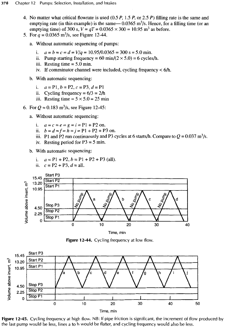
Figure 12-44.
a.
Without automatic sequencing
of
pumps:
i.
a
=
b
=
c
=
d=v/q=
10.95/0.0365
=
300
s =
5.0
min.
ii.
Pump starting
frequency
= 60
min/(2
x
5.0)
= 6
cycles/h.
iii. Resting time
= 5.0
min.
iv.
If
comminutor channel were included, cycling
frequency
<
6/h.
b.
With automatic sequencing:
i.
0
=
Pl,fc
=
P2,c
=
P3,d
= Pl
ii.
Cycling frequency
= 6/3 =
2/h
iii.
Resting time
= 5 x 5.0 = 25 min
6.
For Q =
0.183
m
3
/s,
see
Figure
12-45:
a.
Without automatic sequencing:
i.
a = c = e = g = i = Pl + P2 on.
ii.
b =
d=f=h=j
=
Pl+P2
+
P3on.
iii.
Pl and P2 run
continuously
and P3
cycles
at 6
starts/h.
Compare
to Q =
0.037
m
3
/s.
iv.
Resting period
for P3 = 5
min.
b.
With automatic sequencing:
i.
a = Pl + P2, b = Pl + P2 + P3
(all),
ii. c
=
P2 +
P3,J=all.
Figure
12-44.
Cycling
frequency
at low
flow.
Figure
12-45.
Cycling
frequency
at
high
flow.
NB: If
pipe
friction
is
significant,
the
increment
of
flow
produced
by
the
last
pump
would
be
less,
lines
a to h
would
be
flatter,
and
cycling
frequency
would
also
be
less.
Critique
of
Example
12-3
The
authors emphasize that this
type
of
design
is not
recommended,
although many stations similar
to
Example
12-3
are
constructed each year.
It is
impossi-
ble to
remove scum
and
sludge with
the
main pumps,
because
a
pump intake
can
only suck
up
sludge within
a
distance
of
about
D/4
from
the
intake. Dividing
the
sump
in
half
so
that half
may be
dewatered
for
clean-
ing
implies entry
by an
enthusiastic crew
in
moon
suits,
rubber boots,
and
perhaps self-contained breath-
ing
apparatus working
in a
confined, hazardous space
to
muck
out
scum
and
sludge
by
hand. Entry
and
safety
requirements combined with
the
revolting task
would
ensure
infrequency
of
cleaning and, hence,
an
odiferous
facility.
A
far
more acceptable alternate method
is a
pumper truck with
a flexible
suction hose
for
vacuum-
ing
the
sludge under water, thereby making
the
divid-
ing
wall
superfluous.
Dividing walls with sluice gates
are, nevertheless, common. Sometimes they
are
included
to
facilitate repairs.
Floor
The floor of the
sump
is
much
too
wide,
and
deep
banks
of
sludge will accumulate
on it. The
space
under
the
baffle
channel
is
inadequate
to
prevent
it
from
being clogged with sludge. There
are
several
remedies, such
as a
narrower sump,
flatter
slopes,
or a
deeper sump.
For
this facility,
the
best approach
appears
to be
lowering
the floor to
Elevation 3.35
m as
shown
by the
dashed
lines
in
Figure
12-46.
A
down-
turned
suction bell (actually "flange
and flare 90°
bend")
with
the
mouth
at
elevation 3.52
m
(also
shown
by
dashed lines) makes
a
better intake, because
it
offers
some protection against
the
entry
of
large
heavy
solids,
and it
allows
the floor of the dry
well
to
be 0.4 m
higher than would
a
horizontal intake. Clean-
ing
with
a
pumper truck would still
be
required,
but
the
amount
of
sludge
to be
removed would
be
dimin-
ished.
Baffle
Channel
In a
similar, larger pumping station without
a
baffle
channel, even
a
short cascade
of
water
from
the
inlet
channel into
the
pool
at
low-water levels generated
large masses
of air
bubbles driven down
to the floor
and
into
the
pump intakes, with
the
result that design
pump capacity could
not be
reached, pumps were
noisy,
and
repairs were frequent.
The
baffle
channel
was
effective
in
discharging water horizontally,
allowing bubbles
to
escape
to the
surface,
and
restor-
ing
full
pumping capacity
as
shown
by
model studies.
iii.
e
= P3 +
Pl,/=all.
iv.
£
= Pl +
P2,/i
=
all.
v.
Starts//*
= 6/3 = 2 for any
pump.
vi.
Resting time
=
10.95/0.0365
= 300 s = 5
min
for any
pump.
7.
Diagrams such
as
Figures
12-44
and
12-45
can
easily
be
modified
for
pumps
of
different
sizes and,
of
course,
for any
discharge
or
inflow
rates.
H.
Plans
Plans
for the
above example
are
shown
in
Figure 12-46.
I.
Maximum Detention Time
of
Wastewater
in Wet
Well
1.
To
avoid septic conditions, wastewater should
not be
stored
for
long periods. Allowable
storage
periods
are
site-specific
and
depend
on
travel time
to
treatment plant, strength
and
freshness
of
wastewater, temperature,
and
other factors.
2.
Maximum/minimum
flows
have been reported with considerable variation.
At
Sunset
Beach station
in
Steilacoom, Washington, max/min
=
197/13
L/s,
so
minimum
flow (at
2
A.M.
to
4:30
A.M.
in dry
weather)
is
only
7% of
peak
flow in wet
weather.
3.
Compute detention time
as
average liquid
volume/min
flow.
(Not true detention time
but
rather
a
dilution
factor,
but, like
air
changes/h
in a dry
well, this computation gives some
idea
of
detention time.)
4. Avg
vol
=
10.95/2
(see Figures 12-42
and
12-44)
+
vol
below
LWL
=
5.48
+
(5.09
-
4.23)(6.0)[(2.5
+
1.35)/2]
=
15.41
m
3
.
5.
Flowrate
= 7% max
design
flow =
0.07
x
0.220
m
3
/s
=
0.0154
m
3
/s
6.
For one
dilution,
T=
15.41/0.0154
=
1001
s = 17
min. Seems quite acceptable.
However,
turbulence
in the
baffle
channel promotes
the
release
of
hydrogen
sulfide
from
the
entering liq-
uid. Acid corrosion
and
odors
are
certain
if the
waste-
water
is
stale.
Comminutor
and Bar
Screen
In
some locations, there
may be a
need
for a
commi-
nutor
and a bar
screen,
but
these facilities
can be
omit-
ted in
most pumping stations (see Section
24-1
1,
Item
13).
If the
dividing wall
is
also omitted, only
a
single
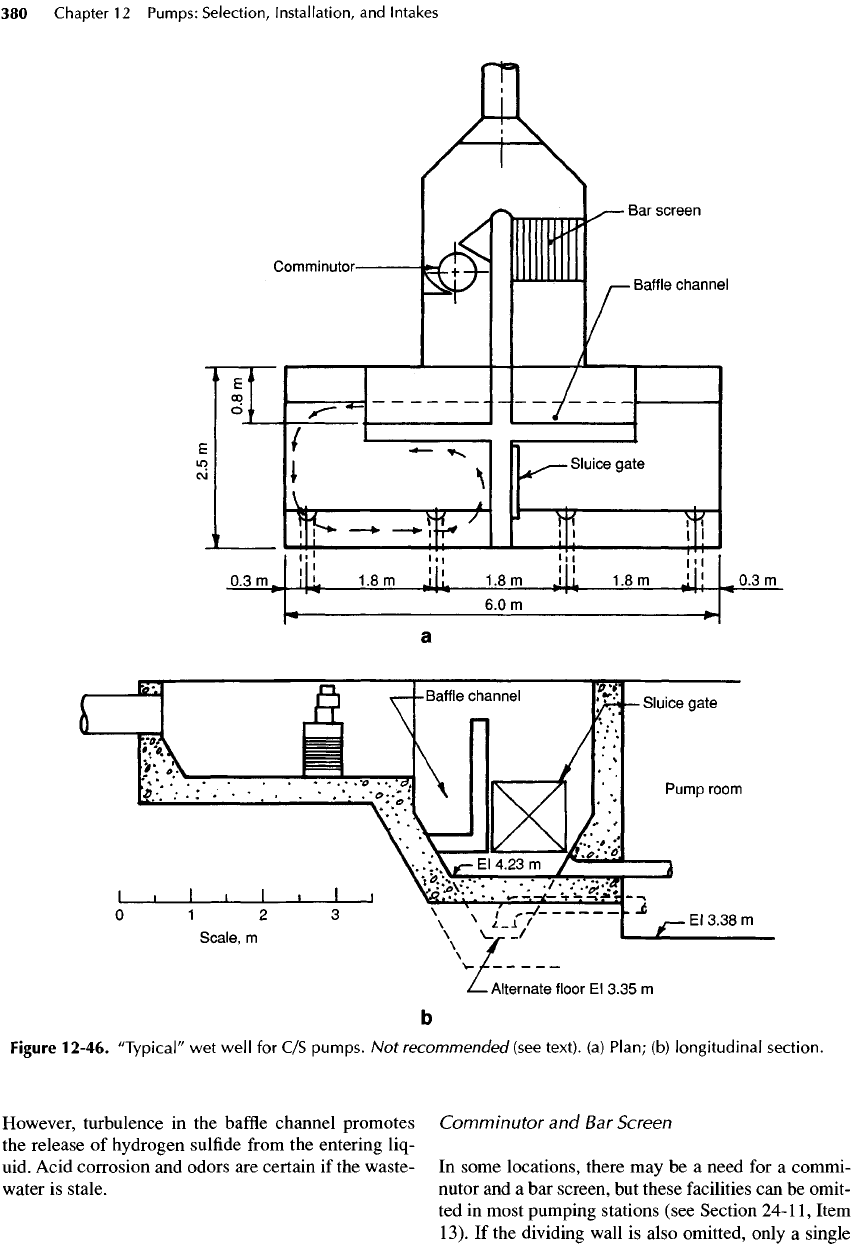
Figure
12-46.
"Typical"
wet
well
for C/S
pumps.
Not
recommended
(see
text),
(a)
Plan;
(b)
longitudinal
section.
channel
from
inlet pipe
to
sump
is
needed,
and
that
channel
can be
shortened
but
deepened
to
serve
the
same purpose
as the
baffle
channel
—
thereby
eliminat-
ing the
need
for the
baffle
channel. Care must
be
taken
to
keep
the
velocity less than about
1.1
m/s
(3.5 ft/s)
lest
currents
at
pump intakes exceed
0.3 m/s (1
ft/s).
On
the
other hand,
the
currents should
be
large
enough
to
scour deposits
from
the
trench frequently.
See
Figure 12-36
for the
velocities required.
Pump
Capacities
Unless
the TDH is due
almost entirely
to
elevation
head
and not to
pipe
friction,
the
capacity
of one
pump
operating alone would
be
greater than one-third
of
the
total capacity.
Two
pumps would have
a
greater
capacity than two-thirds
of the
total capacity. (These
capacities must
be
found
from
the
pump
and
system
H-Q
curves.) More sophisticated expressions than
Equation
12-3
can be
used [20, 21],
but
Equation 12-3
can
still
be
applied
in at
least
two
ways.
• Use the
true capacity
of Pl
acting alone
to find the
volume
required
and to set
stop
and
start levels.
Then
set
stop
and
start levels
for the
follow
pump
at
150 mm (6
in.) higher.
Do the
same
for the
second
follow
pump,
and so on.
•
Find
the
sump volume
for
Pl.
Then
find the
addi-
tional volume
for P2 by
using
the
difference
in
pumping
capacities between
Pl and
Pl
+ P2 for q in
Equation 12-3.
The
difference
in
levels
for
starts
or
stops
of
subsequent pumps must still
be 150 mm.
Graphical
Analysis
of
Pump
Cycling
In
Figures 12-44
and
12-45, ordinates
are wet
well
volumes with equal increments
of
volume shown
by
equal increments
of
ordinates.
The
abscissa
is
time.
Beginning with
an
active sump volume determined
by
using
Equation 12-3, start (and stop) elevations
for
lead
and
follow
pumps
are
plotted
at the
proper
vol-
umes
for
elevation
differences
of
—
typically
—
150
mm
(6
in.).
For two
duty pumps, critical
inflow
rates
are
/?/2
and (1 +
1
I
2
)P-
Both cycle time
and
resting time
for
an
inflow
of
p/2
are
shown
in the figures.
When
one
pump
is
always running,
the
cycle time
can be
doubled (for
two
duty pumps)
by
alternating lead
and
follow
pumps
in
every cycle.
The
graph
can be
easily
modified
for a
different
active volume,
for lag
between starting
and
stopping
a
pump,
for
pumps
of
different
sizes,
and for
changing discharge
with
changing TDH. Flexibility
is
greater
than with mathe-
matical analyses because,
for
example,
different
pump
sequences, start-stop elevations,
and
smart controllers
can be
easily evaluated. Simplicity, ease
of
use,
and
more complete exposition
are
among
the
advantages
of
graphical analysis.
Example
12-4
Design
of a
Trench-Type
Wet
Well
for V/S
Wastewater Pumps
The
design
of a
trench-type
wet
well with
dry pit
pumps operating
at V/S is
illustrated
in
this
example.
The
design capacity
is the
same
as in
Example 12-3.
See
Section 26-2
for a
somewhat
different
wet
well design,
for the use of
computers
to aid
hydraulic calculations,
and for the
design
of the
entire station.
A.
Design Conditions
1.
Q
max
= 220 L/s (5
Mgal/d).
Q
min
=
35 L/s
(0.8 Mgal/d).
2.
Trench-type
wet
well. Plans
are
shown later
in
Figures 12-47, 12-48,
and
12-50.
3.
Use
three (two duty
and one
standby)
pumps—always
the
best
choice
for V/S
pumps
if
the
flowrates can be met at all
times.
4.
Influent
sewer
pipe:
525-mm nominal
(533-mm
true
=
21-in.)
RCP.
5.
LWL at
pipe invert,
HWL at
pipe
soffit.
6.
Pump-speed
controller programmed
for O to 220 L/s
with depth proportional
to Q
(see
Figure 12-35).
7.
No
comminutor
nor bar
screen.
8.
Influent
or
supply pipe
is 533 mm
true
(21
in.)
in
diameter
B.
Size
and
Shape
of
Sump
1.
For
simplicity, assume
the
system curve
is flat and
Q/pump
=110
L/s
(2.5 Mgal/d).
For a
rising
system
curve,
one
pump alone would discharge more than
110
L/s
(see Section 26-2).
2.
Size
the
suction
bell.
a.
Entrance velocity should
be
about
1.1
m/s
(3.5
ft/s).
According
to
Table
17-1,
veloci-
ties
can be 0.6 to 2.7 m/s (2 to 9
ft/s)
but not for
trench-type sumps.
b.
A =
Q/v
=
0.110/1.1=
O.lm
2
.
c. D =
J4A/K
=
74x0.1/71
=
0.357
m = 357 mm.
d.
Suction
bell
(or flare) OD = flange
diameter.
e.
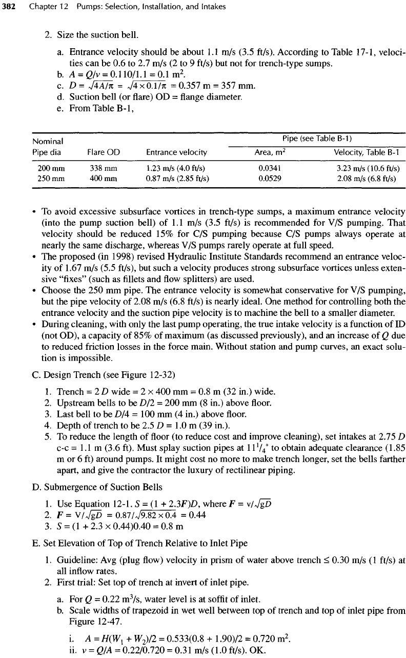
From Table
B-I,
Nominal
Pipe (see Table
B-1)
Pipe
dia
Flare
OD
Entrance
velocity
Area,
m
2
Velocity,
Table
B-1
200mm
338mm
1.23
m/s
(4.0
ft/s)
0.0341 3.23
m/s
(10.6
ft/s)
250 mm 400 mm
0.87
m/s
(2.85
ft/s)
0.0529 2.08
m/s
(6.8 ft/s)
• To
avoid excessive subsurface vortices
in
trench-type sumps,
a
maximum entrance velocity
(into
the
pump suction bell)
of
1.1
m/s
(3.5 ft/s)
is
recommended
for V/S
pumping. That
velocity should
be
reduced
15% for C/S
pumping because
C/S
pumps always operate
at
nearly
the
same discharge, whereas
V/S
pumps rarely operate
at
full
speed.
• The
proposed
(in
1998) revised Hydraulic Institute Standards recommend
an
entrance veloc-
ity
of
1.67
m/s
(5.5
ft/s),
but
such
a
velocity produces strong subsurface vortices unless exten-
sive "fixes" (such
as fillets and flow
splitters)
are
used.
•
Choose
the 250 mm
pipe.
The
entrance velocity
is
somewhat conservative
for V/S
pumping,
but
the
pipe velocity
of
2.08
m/s
(6.8 ft/s)
is
nearly ideal.
One
method
for
controlling both
the
entrance velocity
and the
suction pipe velocity
is to
machine
the
bell
to a
smaller diameter.
•
During cleaning, with only
the
last pump operating,
the
true intake velocity
is a
function
of ID
(not
OD),
a
capacity
of 85% of
maximum
(as
discussed previously),
and an
increase
of Q due
to
reduced
friction
losses
in the
force main. Without station
and
pump curves,
an
exact solu-
tion
is
impossible.
C.
Design Trench (see Figure 12-32)
1.
Trench
= 2 D
wide
=
2 x 400 mm = 0.8 m (32
in.) wide.
2.
Upstream bells
to be D/2 = 200 mm (8
in.) above
floor.
3.
Last bell
to be
D/4
=100
mm (4
in.) above
floor.
4.
Depth
of
trench
to be 2.5 D = 1.0 m (39
in.).
5. To
reduce
the
length
of floor (to
reduce cost
and
improve cleaning),
set
intakes
at
2.75
D
c-c=
1.1
m
(3.6 ft). Must splay suction pipes
at
11V/
to
obtain adequate clearance (1.85
m
or 6 ft)
around pumps.
It
might cost
no
more
to
make trench longer,
set the
bells farther
apart,
and
give
the
contractor
the
luxury
of
rectilinear piping.
D.
Submergence
of
Suction Bells
1.
Use
Equation 12-1.
S = (1 +
2.3F)D,
where
F =
v/Jgb
2. F=
V/
JgD
=
0.87/V9.82
x 0.4 =
0.44
3.
S = (1 + 2.3 x
0.44)0.40
= 0.8 m
E. Set
Elevation
of Top of
Trench Relative
to
Inlet Pipe
1.
Guideline:
Avg
(plug
flow)
velocity
in
prism
of
water above trench
<
0.30
m/s (1
ft/s)
at
all
inflow
rates.
2.
First trial:
Set top of
trench
at
invert
of
inlet pipe.
a. For Q =
0.22
m
3
/s,
water level
is at
soffit
of
inlet.
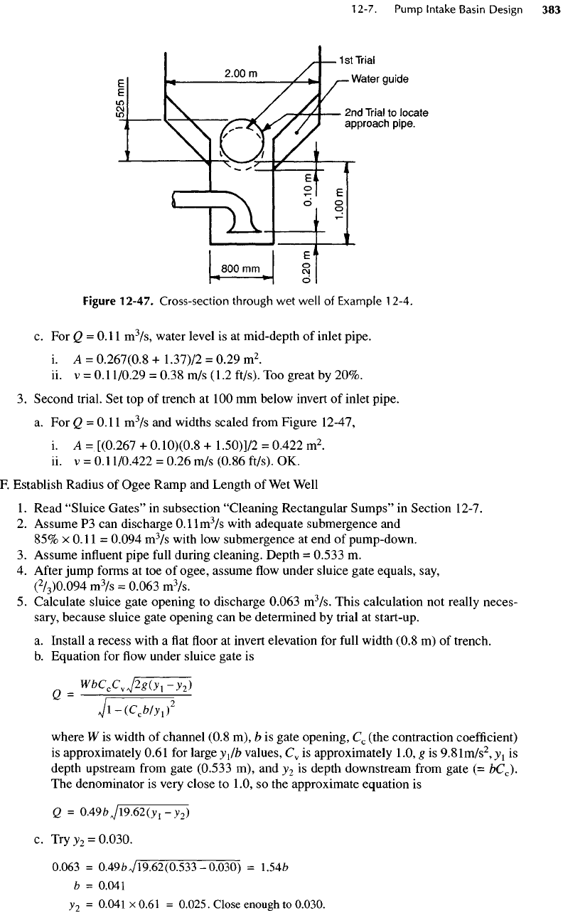
b.
Scale widths
of
trapezoid
in wet
well between
top of
trench
and top of
inlet pipe
from
Figure 12-47.
i.
A=
H(W\
+
W
2
)/2
=
0.533(0.8
+
1.90)12
=
0.720
m
2
.
ii. V =
QfA
=
0.22/0.720
=
0.31
m/s
(1.0
ft/s).
OK.
Figure
12-47.
Cross-section
through
wet
well
of
Example
12-4,
c. For Q =
0.11
m
3
/s,
water level
is at
mid-depth
of
inlet pipe.
i. A =
0.267(0.8
+
1.37)/2
=
0.29
m
2
.
ii. v =
0.11/0.29
=
0.38
m/s
(1.2
ft/s).
Too
great
by
20%.
3.
Second trial.
Set top of
trench
at 100 mm
below invert
of
inlet
pipe,
a.
For Q =
0.11
m
3
/s
and
widths scaled
from
Figure
12-47,
i.
A
=.[(0.267
+
0.10)(0.8
+
1.50)]/2
-
0.422
m
2
.
ii. v =
0.11/0.422
=
0.26
m/s
(0.86
ft/s).
OK.
F.
Establish Radius
of
Ogee Ramp
and
Length
of Wet
Well
1.
Read
"Sluice
Gates"
in
subsection
"Cleaning
Rectangular Sumps"
in
Section
12-7.
2.
Assume
P3 can
discharge
O.llm
3
/s
with adequate submergence
and
85%
x
0.11
=
0.094
m
3
/s
with
low
submergence
at end of
pump-down.
3.
Assume
influent
pipe
full
during cleaning. Depth
=
0.533
m.
4.
After
jump
forms
at toe of
ogee, assume
flow
under sluice gate equals,
say,
(
2
/
3
)0.094
m
3
/s
=
0.063
m
3
/s.
5.
Calculate sluice gate opening
to
discharge
0.063
m
3
/s.
This calculation
not
really neces-
sary,
because sluice gate opening
can be
determined
by
trial
at
start-up.
a.
Install
a
recess with
a flat floor at
invert elevation
for
full
width
(0.8
m) of
trench.
b.
Equation
for flow
under sluice gate
is
Q
_WbC
c
C
v
j2
g
(y
}
-y
2
)
Jl-(C
c
b/
yi
)
2
where
W is
width
of
channel
(0.8
m), b is
gate opening,
C
c
(the contraction
coefficient)
is
approximately
0.61
for
large
yjb
values,
C
v
is
approximately
1.0,
g is
9.81m/s
2
,
V
1
is
depth upstream
from
gate (0.533
m), and
y
2
is
depth downstream
from
gate
(=
bC
c
).
The
denominator
is
very close
to
1.0,
so the
approximate equation
is
Q
=
QA9bJl9.62(
yi
-y
2
)
c.
Try
y
2
=
0.030.
0.063
=
0.49
Wl9.62(0.533-0.030)
=
1.54&
b =
0.041
y
2
=
0.041x0.61
=
0.025.
Close
enough
to
0.030.
