Pumping Station Desing - Second Edition by Robert L. Sanks, George Tchobahoglous, Garr M. Jones
Подождите немного. Документ загружается.

d.
Velocity
a
short distance downstream
from
the
gate
is
v
=
0.0637(0.025x0.80)
=
3.15m/s
e. EGL =
0.025
+
(3.15)
2
/(2
x
9.81)
=
0.531
m
above apron,
so
very little head
is
lost
as
water
flows
under gate.
6.
Radius
of
ogee
from
Equation 12-2:
R
=
2.33
h =
2.33(0.533-0.025/2)
=
1.21
m
7. See
Figure 12-48
for
dimensions.
G.
Design Cleaning Cycle. Those experienced
in
this subject
can
avoid cleaning cycle calculations.
1.
Read "Another Way"
in
subsection
"Cleaning
Rectangular Sumps"
in
Section 12-7.
2.
Work backward
from
end to
beginning
of
pump-down
by
using volumes
of
water
expelled over time.
Consider
inflow
(down
the
sewer
to be 35
L/s)
and
outflow
rates
to get
water
levels
and
required volumes.
See
Figures 12-47 through 12-49.
3.
Trial
1.
Begin with hydraulic jump
at P3 and
upstream water depth
at
J
2
m
Figure
12-49.
Only
P3 can
expel water under these conditions.
a.
d
2
(see Example 12-5) varies
but
averages about
0.030
m.
Ignore
it for
volumetric
and
time calculations.
b.
d
v
«
D/2 +
(D/4
to
D/3)
«
0.75
x 400 mm = 300 mm.
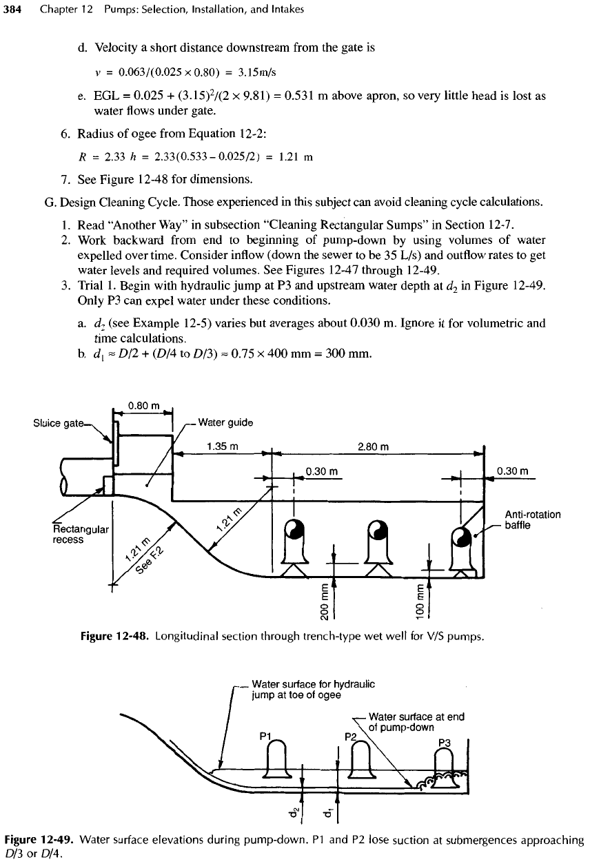
Figure
12-48.
Longitudinal section
through
trench-type
wet
well
for V/S
pumps.
Figure
12-49. Water
surface
elevations during
pump-down.
P1 and P2
lose
suction
at
submergences approaching
D/3 or
D/4.
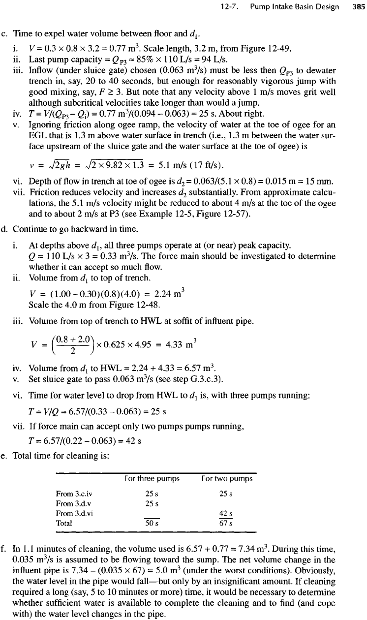
c.
Time
to
expel water volume between
floor and
J
1
.
i.
V = 0.3 x 0.8 x 3.2 =
0.77
m
3
.
Scale length,
3.2
m,
from
Figure 12-49.
ii.
Last pump capacity
=
Q
P3
«
85% x
110
L/s = 94
L/s.
iii.
Inflow
(under sluice gate) chosen
(0.063
m
3
/s)
must
be
less then
Q
P3
to
dewater
trench
in,
say,
20 to 40
seconds,
but
enough
for
reasonably vigorous jump with
good mixing, say,
F
>
3.
But
note that
any
velocity above
1
m/s
moves grit well
although
subcritical
velocities take longer than would
a
jump.
iv.
T =
V/(Q
P3
-
Q
1
)
=
0.77
m
3
/(0.094
-
0.063)
= 25 s.
About right.
v.
Ignoring friction along ogee ramp,
the
velocity
of
water
at the toe of
ogee
for an
EGL
that
is 1.3 m
above water surface
in
trench
(i.e.,
1.3 m
between
the
water sur-
face
upstream
of the
sluice gate
and the
water surface
at the toe of
ogee)
is
v
=
J2gh
=
V2x9.82xl.3
= 5.1 m/s
(17ft/s).
vi.
Depth
of flow in
trench
at toe of
ogee
is
d
2
=
0.063/(5.1
x
0.8)
=
0.015
m = 15 mm.
vii.
Friction reduces velocity
and
increases
J
2
substantially. From approximate calcu-
lations,
the
5.1
m/s
velocity might
be
reduced
to
about
4 m/s at the toe of the
ogee
and
to
about
2 m/s at P3
(see Example 12-5, Figure
12-57).
d.
Continue
to go
backward
in
time.
i.
At
depths above
J
1
,
all
three pumps operate
at (or
near) peak capacity.
2=110
L/s x 3 =
0.33
m
3
/s.
The
force main should
be
investigated
to
determine
whether
it can
accept
so
much
flow,
ii.
Volume
from
J
1
to top of
trench.
V
=
(1.00-0.30)(0.8)(4.0)
=
2.24m
3
Scale
the 4.0 m
from
Figure 12-48.
iii. Volume
from
top of
trench
to HWL at
soffit
of
influent
pipe,
y
=
(0-8+
2-0)
x
0.625
x
4.95
=
4.33m
3
iv.
Volume
from
J
1
to HWL =
2.24
+
4.33
=
6.57
m
3
.
v.
Set
sluice gate
to
pass
0.063
m
3
/s
(see step
G.3.C.3).
vi.
Time
for
water level
to
drop
from
HWL to
J
1
is,
with three pumps running:
T=VfQ
=
6.57'/(0.33
-
0.063)
= 25 s
vii.
If
force main
can
accept only
two
pumps pumps running,
T
=
6.577(0.22
-
0.063)
= 42 s
e.
Total time
for
cleaning
is:
For
three pumps
For two
pumps
From
S.c.iv
25 s 25 s
From
S.d.v
25 s
From
S.d.vi
42 s
Total
50s
Wl
f.
In
1.1
minutes
of
cleaning,
the
volume used
is
6.57
+
0.77
=
7.34
m
3
.
During this time,
0.035
m
3
/s
is
assumed
to be flowing
toward
the
sump.
The net
volume change
in the
influent
pipe
is
7.34
-
(0.035
x 67) = 5.0
m
3
(under
the
worst conditions). Obviously,
the
water level
in the
pipe would
fall—but
only
by an
insignificant amount.
If
cleaning
required
a
long (say,
5 to 10
minutes
or
more) time,
it
would
be
necessary
to
determine
whether
sufficient
water
is
available
to
complete
the
cleaning
and to find
(and cope
with)
the
water level changes
in the
pipe.
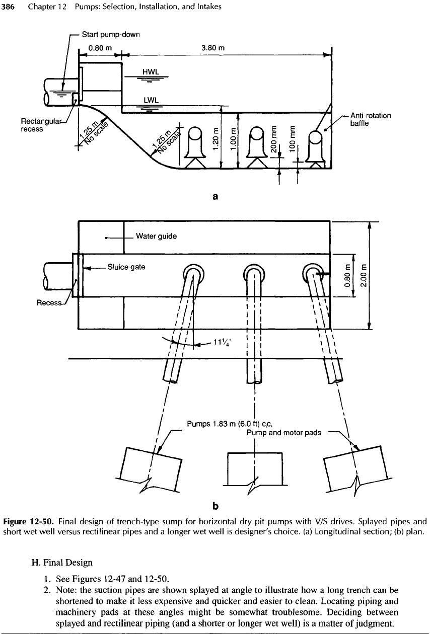
Figure
12-50.
Final design
of
trench-type sump
for
horizontal
dry pit
pumps
with
V/S
drives. Splayed pipes
and
short
wet
well
versus
rectilinear pipes
and a
longer
wet
well
is
designer's
choice,
(a)
Longitudinal
section;
(b)
plan.
H.
Final Design
1.
See
Figures 12-47
and
12-50.
2.
Note:
the
suction pipes
are
shown splayed
at
angle
to
illustrate
how a
long trench
can be
shortened
to
make
it
less expensive
and
quicker
and
easier
to
clean. Locating piping
and
machinery
pads
at
these angles might
be
somewhat troublesome. Deciding between
splayed
and
rectilinear piping (and
a
shorter
or
longer
wet
well)
is a
matter
of
judgment.
Critique
of
Example
12-4
Trench-type
wet
wells
for V/S
pumping
are
easy
to
design.
The
only concerns are:
•
Size
and
submergence
of the
suction bell.
•
Elevation
of the
influent
pipe
and the
water level
within
it to
keep
the
average (plug
flow)
velocity
above
the
trench below
0.3 m/s
(1
ft/s) at all flowrates.
•
Enough water available
for
pump-down
and
cleaning.
• A
reasonable radius
for the
ogee ramp.
•
High velocity along
the
trench
to the
last pump
to
ensure rapid movement
of
grit. Froude numbers
greater than about
3
suspend grit, with
the
result
that
the
channel
is
swept clean many times
faster
than
at
lesser Froude numbers.
The
ideal
is to
pro-
duce
a
Froude number
of
about
3 at the
last pump,
but
any
velocity greater than
1
.5
m/s (5
ft/s) moves
grit
reasonably well (see Figure 12-36).
A
method
for
calculating Froude numbers
by
suc-
cessive trial
is
given
in
Example 12-5
for
general
interest.
It is
not, however, necessary
to
calculate
Froude numbers
for wet
wells
of
reasonably similar
geometry
and
dimensions, because cleaning
can be
effective
even
if the
Froude numbers vary substan-
tially
from
those
in the
example. Furthermore, Froude
numbers
can be
modified
by
changing
the
cleaning
procedure
—
for
example,
by an
increase
in the
sluice
gate opening.
The
prudent engineer will, however, cal-
culate
Froude numbers
for
unusual circumstances,
for
large stations,
for
trenches that
are
relatively longer
than
the one in the
example,
and
perhaps
for the first
trench-type station encountered.
If
a
piping arrangement similar
to
that
in
Figure
17-13
is
used,
the
minimum satisfactory spacing
for
the
pumps
is
about
1.8
m
(6
ft).
If
suction piping were
rectilinear (i.e.,
at 90° to the
trench),
the wet
well
would
be 1.4 m
(4.6
ft)
longer
and
somewhat more
expensive because
of the
additional
PVC
lining
and
form
work.
The
shorter
one
would
be
easier
and
quicker
to
clean.
On the
other hand,
the
contractor
might
find
nonrectilinear
layout more
difficult
and
charge somewhat higher unit prices.
The
choice
is a
matter
of
judgment
and
personal preference.
Example
12-5
Design
of a
Trench-Type
Wet
Well
for C/S
Wastewater
Pumps
To
prevent
a
cascade into
the
sump
at LWL and to
obtain more storage
so
that
the
sump
can be
smaller
and
cleaned more easily,
an
approach pipe larger than
the
sewer will
be
laid
at a 2%
gra-
dient
between
an
upstream manhole
and the
sump.
Its
free
(above normal
flow)
volume
is
con-
sidered part
of the
active storage
of the
sump.
Again,
the
following presentation
is
detailed and, consequently,
may
seem tedious
and
time-
consuming.
Wheeler's PARTFULL® program [25] makes short work
of
many
of the
calcula-
tions.
Note that operations
can
(and should)
be
adjusted
during start-up
to fit the
design
and the
actual
flowrates
encountered.
A.
Design Conditions
1.
C
max
= 220 L/s (5
Mgal/d).
g
min
= 35 L/s
(0.8
Mgal/d).
2.
Two
duty pumps discharge
220 L/s
together plus
one
standby.
3.
Trench-type
wet
well.
4.
Influent
sewer pipe:
RCP 525 mm
nominal
dia
(535
mm
true
= 21
in.)
5.
Maximum pump start frequency
=
6/h,
but
less
is
better.
B.
Select Size
of
Approach Pipe
1.
Read subsection "Approach
Pipe"
in
Section 12-7.
2.
Convert
% in
Table 12-2
to
numerical values (see also Table B-8).
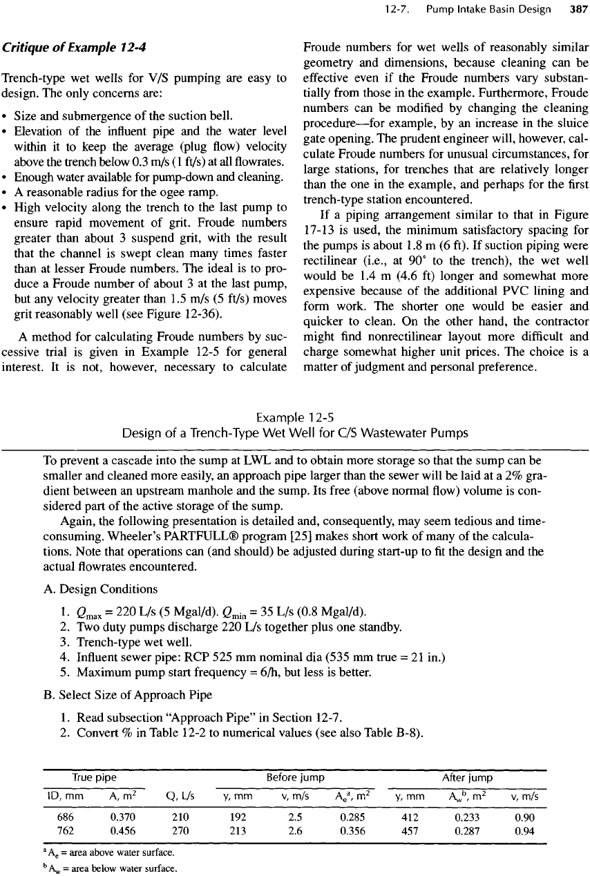
True
pipe
Before
jump
After
jump
ID,
mm
A,
m
2
Q,
L/s y, mm
v,
m/s
A
e
a
,
m
2
y, mm
A
w
b
,
m
2
v, m/s
686
0.370
210 192 2.5
0.285
412
0.233 0.90
762
0.456
270 213 2.6
0.356
457
0.287 0.94
3
A
6
=
area
above
water
surface.
b
A
w
=
area
below
water
surface.
3. Q for
nominal 675-mm (27-in.)
pipe
is 3% too
low.
4. Q for
nominal
750-mm
(30-in.)
pipe
is 25% too
high.
5.
Choose nominal 675-mm pipe (actually
686
mm).
C.
Size
and
Shape
of
Sump
1.
Use
three
pumps—two
duty
(to
pump
220 L/s
together)
and one
standby.
2.
(2/pump
=110
L/s
(2.5
Mgal/d
or
1740
gal/min)
only when both pumps
are
operating.
In
a
system
with
significant
pipe
friction,
a
single pump would,
as
noted previously, dis-
charge more because
of
reduced
friction
head. However,
for
simplicity
in
this example,
assume
that
a
pump operating alone discharges
110
L/s.
3.
Size
of
suction
bell
= 400 mm for
250-mm
pipe.
See
Example
12-4.
4.
Design trench
to be the
same
as in
Example 12-4, Parts
C.I
through C.4.
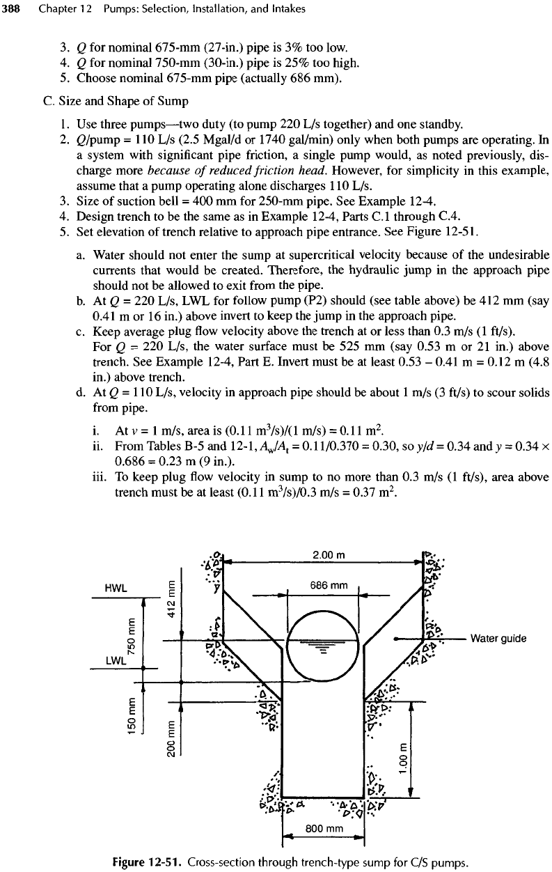
5. Set
elevation
of
trench relative
to
approach pipe entrance.
See
Figure
12-51.
a.
Water should
not
enter
the
sump
at
supercritical velocity because
of the
undesirable
currents that would
be
created.
Therefore,
the
hydraulic jump
in the
approach
pipe
should
not be
allowed
to
exit
from
the
pipe.
b.
AiQ
= 220
L/s,
LWL for
follow
pump (P2) should (see table above)
be 412 mm
(say
0.41
m or
16
in.) above invert
to
keep
the
jump
in the
approach
pipe.
c.
Keep average plug
flow
velocity above
the
trench
at or
less than
0.3
m/s
(1
ft/s).
For Q = 220
L/s,
the
water surface must
be 525 mm
(say 0.53
m or 21
in.) above
trench.
See
Example 12-4, Part
E.
Invert must
be at
least 0.53
-
0.41
m =
0.12
m
(4.8
in.) above trench.
d. At Q =
110
L/s, velocity
in
approach pipe should
be
about
1 m/s (3
ft/s)
to
scour solids
from
pipe.
i. At v = 1
m/s, area
is
(0.11
m
3
/s)/(l
m/s)
=
0.11
m
2
.
ii.
From Tables
B-5 and
12-I
9
AJA
1
=
0.11/0.370
=
0.30,
so
y/d
=
0.34
and y =
0.34
x
0.686
=
0.23
m (9
in.),
iii.
To
keep plug
flow
velocity
in
sump
to no
more than
0.3 m/s (1
ft/s),
area above
trench must
be at
least
(0.11
m
3
/s)/0.3
m/s =
0.37
m
2
.
Figure
12-51.
Cross-section
through
trench-type
sump
for C/S
pumps.
iv.
Place invert 0.20
m
(instead
of
0.12
m)
above trench. Water depth above trench
=
0.20
+
0.23
=
0.43
m, and
wetted area above trench
=
(0.43)[0.8
+
(0.8
+ 2 x
0.43)]/2
=
0.53
m
2
.
V = QIA =
0.11/0.53
=
0.21 m/s.
OK
because
< 0.3
m/s. (Actu-
ally,
placing
the top of the
trench
0.12
m
below
the
invert would have been satis-
factory,
but the
added area
and
reduced currents provide more benign conditions
for
the
pumps. Designing
to the
limit
is not
always best.)
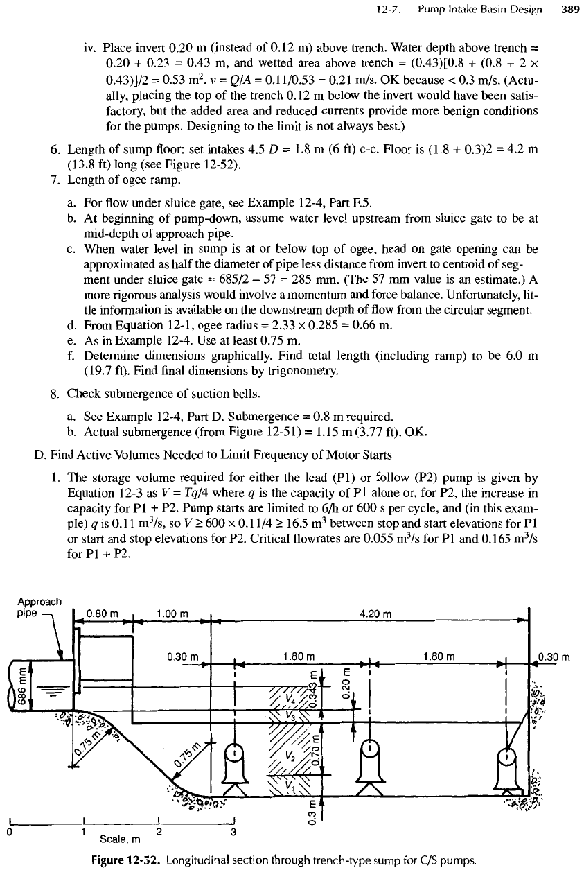
6.
Length
of
sump
floor: set
intakes
4.5 D = 1.8 m (6 ft)
c-c. Floor
is
(1.8
+
0.3)2
= 4.2 m
(13.8
ft)
long (see Figure 12-52).
7.
Length
of
ogee ramp.
a.
For flow
under sluice gate,
see
Example 12-4, Part F.5.
b.
At
beginning
of
pump-down, assume water level upstream
from
sluice gate
to be at
mid-depth
of
approach pipe.
c.
When water level
in
sump
is at or
below
top of
ogee,
head
on
gate opening
can be
approximated
as
half
the
diameter
of
pipe less distance
from
invert
to
centroid
of
seg-
ment
under sluice gate
^
685/2
- 57 = 285 mm.
(The
57 mm
value
is an
estimate.)
A
more rigorous analysis would involve
a
momentum
and
force balance. Unfortunately, lit-
tle
information
is
available
on the
downstream depth
of flow
from
the
circular segment.
d.
From Equation 12-1, ogee radius
=
2.33
x
0.285
=
0.66
m.
e. As in
Example 12-4.
Use at
least 0.75
m.
f.
Determine dimensions graphically. Find total length (including ramp)
to be 6.0 m
(19.7
ft). Find
final
dimensions
by
trigonometry.
8.
Check submergence
of
suction
bells.
a.
See
Example 12-4, Part
D.
Submergence
= 0.8 m
required.
b.
Actual submergence
(from
Figure 12-51)
=
1.15
m
(3.77 ft).
OK.
D.
Find Active Volumes Needed
to
Limit Frequency
of
Motor Starts
1.
The
storage volume required
for
either
the
lead (Pl)
or
follow (P2) pump
is
given
by
Equation
12-3
as V =
Tq/4 where
q is the
capacity
of Pl
alone
or, for P2, the
increase
in
capacity
for Pl + P2.
Pump starts
are
limited
to
6/h
or 600 s per
cycle,
and (in
this exam-
ple)
q is
0.11
m
3
/s,
so V
>
600 x
0.11/4
>
16.5
m
3
between stop
and
start elevations
for Pl
or
start
and
stop elevations
for P2.
Critical
flowrates are
0.055
m
3
/s
for Pl and
0.165
m
3
/s
for
Pl + P2.
Figure
12-52.
Longitudinal
section
through
trench-type
sump
for C/S
pumps.
2.
Bear
in
mind that
at any flow, the
volume occupied
by
water
flowing
down
the
approach
pipe
and
pooling before
it
enters
the wet
well
is
unavailable
for
active storage.
3.
Also bear
in
mind that there should
be
about
150
mm (6
in.)
difference
in
elevation levels
for
starting
or
stopping successive pumps
(Pl and P2 in
this example)
to
avoid spurious
starts
or
stops caused
by
wave action
in the
sump.
4.
From Part C.5.d.ii above,
the
level
for
stop
Pl is
0.23
m (9
in.) above invert
and
from
Part
C.5.b, Stop
P2 is
0.41
m (16
in.) above invert.
5.
Compute active volumes
in
sump
and
approach
pipe
(by
scaling
distances
in
Figures
12-52
and
12-53) corresponding
to
these levels,
add
16.5
m
3
to
each
and
compute comparable
start
levels
for
these volumes (best done
by
computer,
as
calculations
by
hand
are
tedious).
Adjust
start
P2 to
make
it 150 mm
higher than start
Pl.
Elevations above invert are:
a.
Stop
Pl at
0.23
m
above invert
and
stop
P2 at
0.41
m.
Difference
=
0.18
m,
which
is >
0.15
m. OK.
b.
Start
Pl at
1.00
m
above invert
and
start
P2 at
1.15
m.
Difference
=
0.15m.
OK.
6.
See
Figure 12-54
for
graphical depiction
of
pump starting frequency.
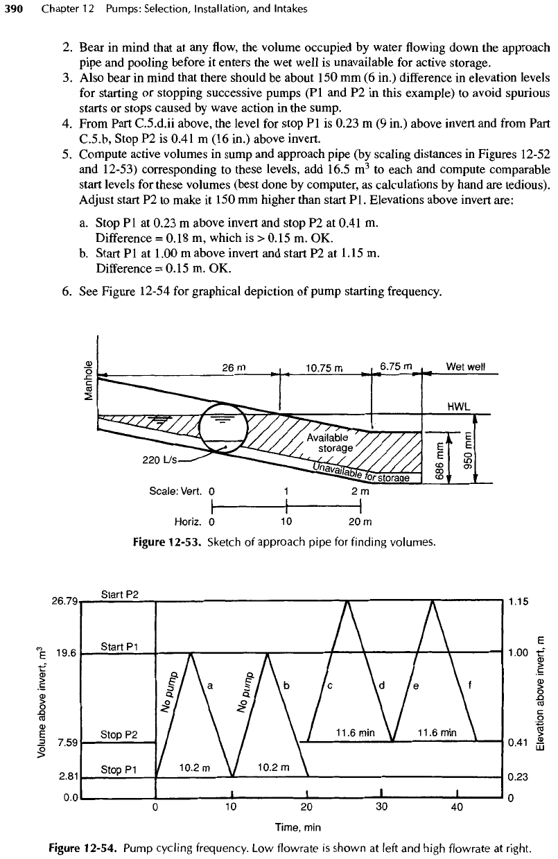
Figure
12-53.
Sketch
of
approach
pipe
for
finding
volumes.
Figure
12-54.
Pump
cycling
frequency.
Low
flowrate
is
shown
at
left
and
high
flowrate
at
right.
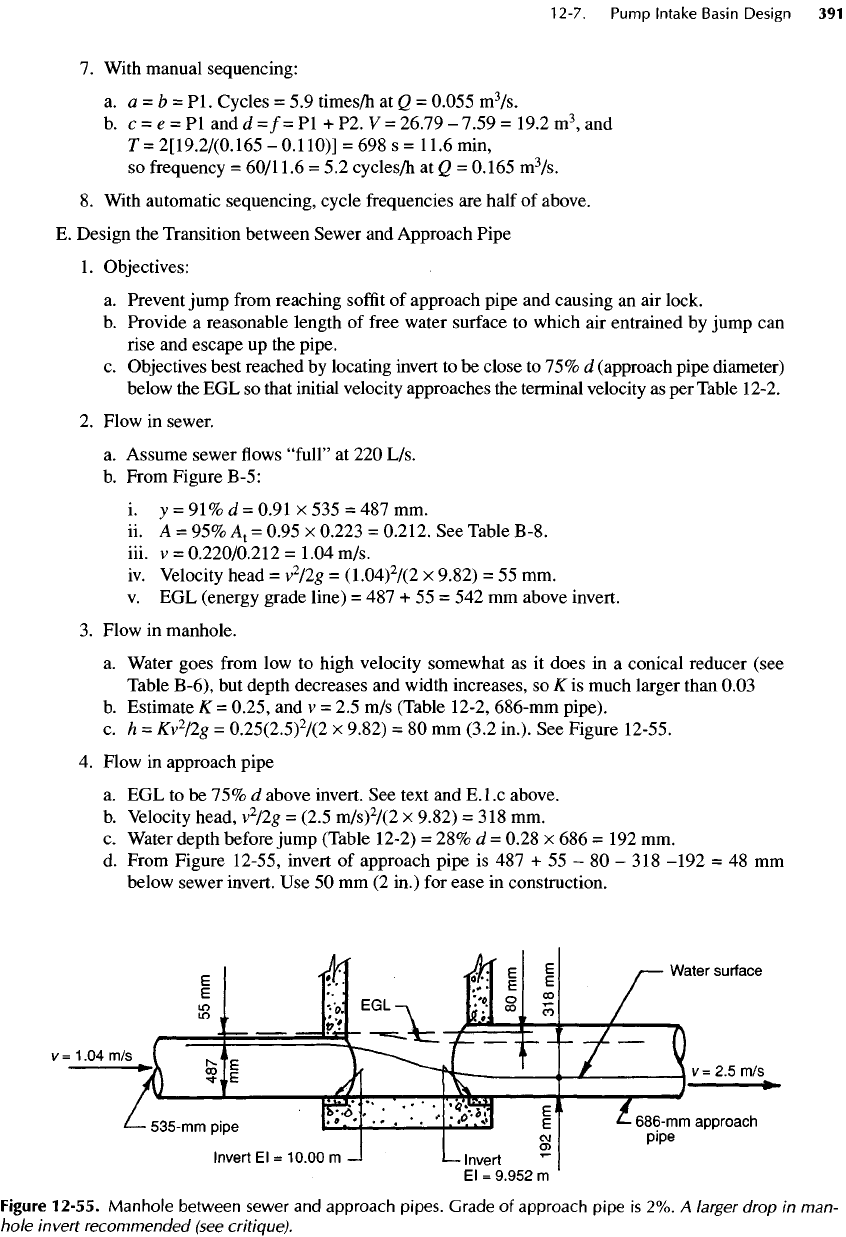
7.
With manual sequencing:
a.
a = b
=
Pl.
Cycles
= 5.9
times/h
at Q =
0.055
m
3
/s.
b.
c = e = Pl
and
d =/= Pl + P2. V =
26.79
-
7.59
=
19.2
m
3
, and
T=
2[19.2/(0.165
-0.11O)]
= 698 s =
11.6
min,
so
frequency
=
60/11.6
= 5.2
cycles/h
at Q =
0.165
m
3
/s.
8.
With automatic sequencing, cycle frequencies
are
half
of
above.
E.
Design
the
Transition between Sewer
and
Approach Pipe
1.
Objectives:
a.
Prevent jump
from
reaching
soffit
of
approach pipe
and
causing
an air
lock.
b.
Provide
a
reasonable length
of
free
water surface
to
which
air
entrained
by
jump
can
rise
and
escape
up the
pipe.
c.
Objectives best reached
by
locating invert
to be
close
to 75% d
(approach pipe diameter)
below
the EGL so
that initial velocity approaches
the
terminal velocity
as per
Table
12-2.
2.
Flow
in
sewer.
a.
Assume sewer
flows
"full"
at 220
L/s.
b.
From Figure
B-5:
i. y
=
91% d
=
0.91
x 535 = 487 mm.
ii. A = 95%
A
1
=
0.95
x
0.223
=
0.212.
See
Table B-8.
iii.
v =
0.220/0.212
=
1.04 m/s.
iv.
Velocity head
=
v
2
/2g
=
(1.04)
2
/(2
x
9.82)
= 55 mm.
v.
EGL
(energy grade line)
= 487 + 55 = 542 mm
above invert.
3.
Flow
in
manhole.
a.
Water goes
from
low to
high velocity somewhat
as it
does
in a
conical reducer (see
Table B-6),
but
depth decreases
and
width increases,
so K is
much larger than 0.03
b.
Estimate
K =
0.25,
and v = 2.5 m/s
(Table 12-2, 686-mm pipe).
c.
h =
Kv
2
/2g
=
0.25(2.5)
2
/(2
x
9.82)
= 80 mm
(3.2
in.).
See
Figure 12-55.
4.
Flow
in
approach pipe
a.
EGL to be 75% d
above invert.
See
text
and
E.l.c
above.
b.
Velocity head,
v
2
/2g
=
(2.5
m/s)
2
/(2
x
9.82)
=
318
mm.
c.
Water depth before jump (Table 12-2)
= 28% d =
0.28
x 686 = 192 mm.
d.
From Figure 12-55, invert
of
approach pipe
is 487 + 55 - 80 - 318
-192
= 48 mm
below
sewer invert.
Use 50 mm (2
in.)
for
ease
in
construction.
Figure
12-55.
Manhole
between
sewer
and
approach pipes. Grade
of
approach
pipe
is 2%. A
larger drop
in
man-
hole
Invert recommended (see
critique).
F.
Cleaning: Volumes
and the
Time Required
1.
Volumes
V
1
to
V
4
are
shown
in
Figure 12-52.
2.
Volumes
of
water
to be
expelled:
a.
V
1
= H
x
W x L
=
0.3 x 0.8 x 4.7 = 1.1 m
3
.
Scale lengths
from
Figure 12-52.
b.
V
2
= 0.7 x 0.8 x 5.2
-
2.9
m
3
.
c.
V
3
=
0.2[(0.8
+
1.2)/2](5.6)
= 1.1
m
3
.
d.
V
4
=
(0.686/2){
[(1.2
+
1.9)72]
[5.25
+
(between water guides)0.8
x
0.75]}
= 3.1
m
3
.
3.
Start
at
beginning
of
pump-down cycle with water level
at
mid-depth
of
approach pipe.
a.
Assume force main
can
accept discharge
from
all
three pumps.
Q
out
~
3 x
0.11
=
0.33
m
3
/s.
(In a
real problem, obtain
from
pump
and
system
H-Q
curves.)
b.
<2
in
is flow
under sluice gate. When sump
is
dewatered
to
invert
of
approach
pipe,
<2
in
= 63
L/s,
and
gradually decreases
as
upstream water surface
falls.
Ignore this
decrease.
c.
Time
to
expel
a
volume
=
T=
Vf(Q
0
-
Q
1
)
=
V/(0.33
-
0.063)
-
V/0.267
seconds.
d.
V
4
.
7=3.1/0.267
= 12 s.
e.
V
3
.
T
=1.1/0.261
= 4 s.
f.
V
2:
7=2.9/0.267
=11
s.
g.
V
1
:
Pl and P2
lose suction.
P3
discharges
-85%
of
0.11
=
0.094
m
3
/s,
so
T =
1.1/(0.094
-
0.063)
= 35 s
h.
Total cleaning time
= 62 s
~
1
min.
4.
Storage volume required:
a.
During pump-down,
63 L/s flows
under sluice gate while
35 L/s flows
into approach
pipe.
Net
approach pipe loss
= 28
L/s.
b.
V
required
= (62
s)(63
- 35) =
1740
L=1.7
m
3
.
c. The
volume used causes
the
water level upstream
to
fall
about
120 mm, so
there
is
more than enough storage
for
cleaning.
G.
Check Froude Number
(F) at
Last Pump.
1.
Unusual conditions (such
as
long trenches) require
the
following calculations
for
veloci-
ties
and
Froude numbers. Those with little experience
in
designing self-cleaning, trench-
type
pumping stations should also complete them until
experience
can
lead
to
short-cuts.
Note
that failure
to
have neat,
clear,
and
understandable calculations
of
every
phase
of
a
project
leads
to
trouble
for
reviewers,
for
other engineers, and,
of
course,
in
court.
It is
not
necessary
for
engineers
who
have
had
considerable experience with trench-type
wet
wells
to
calculate Froude numbers
for
common heights
of the
ogee ramps
and
lengths
of
trench,
because changing
the
mode
of
operation
can
accommodate
a
wide variety
of
dimensions. Note, too, that without
the
ogee ramp, most
of the
sludge
in the
original
trench-type
wet
wells
was
ejected within
a
couple
of
minutes.
The
ramp simply makes
cleaning much more
effective
and
quicker.
The
following calculations
are
presented both
for
general interest
and for
guidance when they
may be
needed.
2. The
dimensionless Froude number
(F)
should
be
about
3 or
more
for the
jump
to
have
enough
energy
to
suspend immediately
all
particles within
its
influence.
An F
greater than
8,
however,
entrains
a
great deal
of
air,
and so
such large values should
be
avoided near
the
last
pump.
For the
usual sump,
a
Froude number greater than about
5 at the
last pump
is
unlikely.
3. One
procedure
for
calculating velocities along
the
trench
is the use of
successive approxi-
mations made
by
dividing
the
ogee
ramp
and the
trench into short
sections.
Begin
the
pro-
cess
by finding the
sluice gate opening
to
pass
0.063
m
3
/s
of flow, and find the
average
velocity
of the flow
under
the
gate.
The flow
from
a
circular segment splashing onto
a flat
apron
is not
uniform,
and
errors
are
likely
to be
large,
so
make calculations conserva-
tively.
Note, however, that
flow
under
the
sluice gate provides much better hydraulic con-
ditions
along
the
trench when discharged through
a
slot
(formed
by the
sluice gate
and
the
apron)
that
is
uniform
in
depth
from
wall
to
wall
of the
water guide.
See
Example
12-4. Flow through
a
circular segment
is
shown
in
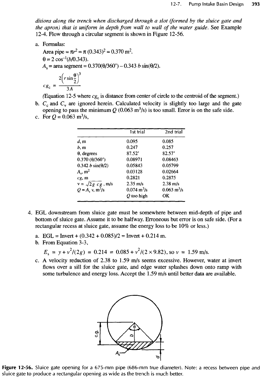
Figure 12-56.
a.
Formulas:
Area
pipe
=
nr
2
=
n
(0.343)
2
=
0.370
m
2
.
6
=
2cos-
1
(£/0.343).
A
8
=
area segment
=
0.370(9/360°)
-
0.343
b
sin(0/2).
'H!)
5
c
*'-^r-
(Equation
12-5
where
cg
c
is
distance
from
center
of
circle
to the
centroid
of the
segment.)
b.
C
c
and
C
v
are
ignored herein. Calculated velocity
is
slightly
too
large
and the
gate
opening
to
pass
the
minimum
Q
(0.063
m
3
/s)
is too
small. Error
is on the
safe
side.
c. For Q
=
0.063
m
3
/s,
1
st
trial
2nd
trial
d,
m
0.095 0.085
b,
m
0.247 0.257
6,
degrees
87.52°
82.57°
0.370(0/360°)
0.08971 0.08463
0.342
b
sin(6/2)
0.05843 0.05799
A
8
,
m
2
0.03128
0.02664
eg,
m
0.2821 0.2875
v
=
V2g
eg
, m/s
2.35
m/s
2.38
m/s
Q=A
s
v,
m
3
/s
0.074
m
3
/s
0.063
m
3
/s
Q too
high
OK
4. EGL
downstream
from
sluice gate must
be
somewhere between mid-depth
of
pipe
and
bottom
of
sluice gate. Assume
it to be
halfway.
Erroneous
but
error
is on
safe
side. (For
a
rectangular recess
at
sluice gate, assume
the
energy loss
to be 10% or
less.)
a.
EGL =
Invert
+
(0.342
+
0.085)/2
=
Invert
+
0.214
m.
b.
From Equation 3-3,
£
s
= y +
v
2
/(2g)
=
0.214
=
0.085
+
v
2
/(2x9.82),sov
=
1.59 m/s.
c.
A
velocity reduction
of
2.38
to
1.59
m/s
seems excessive. However, water
at
invert
flows
over
a
sill
for the
sluice gate,
and
edge water splashes down onto ramp with
some turbulence
and
energy loss. Accept
the
1.59
m/s
until better data
are
available.
Figure
12-56.
Sluice
gate opening
for a
675-mm
pipe
(686-mm
true diameter).
Note:
a
recess
between pipe
and
sluice
gate
to
produce
a
rectangular opening
as
wide
as the
trench
is
much better.
