Pumping Station Desing - Second Edition by Robert L. Sanks, George Tchobahoglous, Garr M. Jones
Подождите немного. Документ загружается.

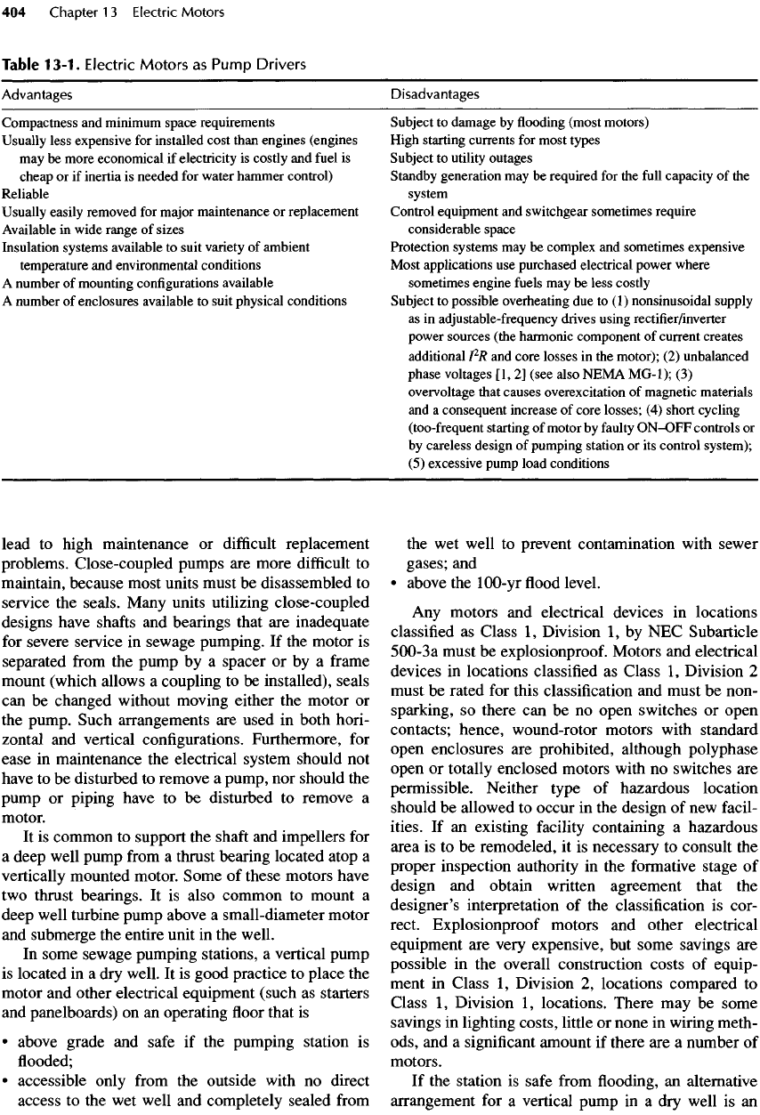
Table
13-1.
Electric
Motors
as
Pump
Drivers
Advantages
Compactness
and
minimum
space requirements
Usually
less expensive
for
installed cost than engines (engines
may
be
more economical
if
electricity
is
costly
and
fuel
is
cheap
or if
inertia
is
needed
for
water hammer control)
Reliable
Usually
easily removed
for
major
maintenance
or
replacement
Available
in
wide range
of
sizes
Insulation systems available
to
suit variety
of
ambient
temperature
and
environmental conditions
A
number
of
mounting configurations available
A
number
of
enclosures available
to
suit
physical conditions
lead
to
high maintenance
or
difficult
replacement
problems. Close-coupled pumps
are
more
difficult
to
maintain,
because most units must
be
disassembled
to
service
the
seals. Many
units
utilizing close-coupled
designs have
shafts
and
bearings that
are
inadequate
for
severe service
in
sewage pumping.
If the
motor
is
separated
from
the
pump
by a
spacer
or by a
frame
mount
(which allows
a
coupling
to be
installed), seals
can be
changed without moving either
the
motor
or
the
pump. Such arrangements
are
used
in
both hori-
zontal
and
vertical
configurations.
Furthermore,
for
ease
in
maintenance
the
electrical
system should
not
have
to be
disturbed
to
remove
a
pump,
nor
should
the
pump
or
piping have
to be
disturbed
to
remove
a
motor.
It
is
common
to
support
the
shaft
and
impellers
for
a
deep well pump
from
a
thrust bearing located atop
a
vertically
mounted motor. Some
of
these motors have
two
thrust bearings.
It is
also common
to
mount
a
deep well turbine pump above
a
small-diameter motor
and
submerge
the
entire unit
in the
well.
In
some sewage pumping stations,
a
vertical pump
is
located
in a dry
well.
It is
good practice
to
place
the
motor
and
other
electrical
equipment (such
as
starters
and
panelboards)
on an
operating
floor
that
is
•
above grade
and
safe
if the
pumping station
is
flooded;
•
accessible only
from
the
outside with
no
direct
access
to the wet
well
and
completely sealed
from
Disadvantages
Subject
to
damage
by flooding
(most motors)
High starting currents
for
most types
Subject
to
utility outages
Standby
generation
may be
required
for the
full
capacity
of the
system
Control equipment
and
switchgear
sometimes require
considerable
space
Protection
systems
may be
complex
and
sometimes expensive
Most applications
use
purchased
electrical
power where
sometimes engine
fuels
may be
less costly
Subject
to
possible
overheating
due to (1)
nonsinusoidal supply
as in
adjustable-frequency drives using rectifier/inverter
power sources (the harmonic component
of
current
creates
additional
I
2
R
and
core
losses
in the
motor);
(2)
unbalanced
phase voltages
[1, 2]
(see
also
NEMA
MG-I);
(3)
overvoltage
that causes overexcitation
of
magnetic materials
and
a
consequent
increase
of
core
losses;
(4)
short cycling
(too-frequent
starting
of
motor
by
faulty
ON-OFF
controls
or
by
careless
design
of
pumping station
or its
control system);
(5)
excessive pump load conditions
the wet
well
to
prevent contamination with sewer
gases;
and
•
above
the
100-yr
flood
level.
Any
motors
and
electrical devices
in
locations
classified
as
Class
1,
Division
1, by NEC
Subarticle
500-3a
must
be
explosionproof. Motors
and
electrical
devices
in
locations
classified
as
Class
1,
Division
2
must
be
rated
for
this classification
and
must
be
non-
sparking,
so
there
can be no
open switches
or
open
contacts; hence, wound-rotor motors with standard
open enclosures
are
prohibited, although polyphase
open
or
totally enclosed motors with
no
switches
are
permissible. Neither type
of
hazardous location
should
be
allowed
to
occur
in the
design
of new
facil-
ities.
If an
existing
facility
containing
a
hazardous
area
is to be
remodeled,
it is
necessary
to
consult
the
proper inspection authority
in the
formative stage
of
design
and
obtain written agreement that
the
designer's interpretation
of the
classification
is
cor-
rect. Explosionproof motors
and
other
electrical
equipment
are
very expensive,
but
some savings
are
possible
in the
overall construction costs
of
equip-
ment
in
Class
1,
Division
2,
locations compared
to
Class
1,
Division
1,
locations. There
may be
some
savings
in
lighting costs,
little
or
none
in
wiring meth-
ods,
and a
significant
amount
if
there
are a
number
of
motors.
If
the
station
is
safe
from
flooding, an
alternative
arrangement
for a
vertical pump
in a dry
well
is an
open
dripproof
motor frame-mounted above
the
pump.
This arrangement avoids
a
long
shaft
and
inter-
mediate supports. If
flooding
is a possibility, submers-
ible motors
can be
installed,
but the
problem
of
ambient
air
cooling
for
normal operating conditions
usually
requires substantial derating
of the
motors.
Note that
the
ordinary pump cannot
be
operated while
submerged without damage
to
seals
and
bearings.
Still another alternative
is the
close-coupled sub-
mersible pump
and
motor mounted
on
slide rails
in
the wet
well.
These
units
are
increasing
in
popularity
because
of the
overall
low
initial cost
due to
savings
in
the
superstructure.
The
motors, however,
are
subject
to
loss
of
seals, penetration
of
moisture,
and
overheat-
ing
if the
pumping level drops below
the
motor. Main-
tenance costs
(1)
depend
on the
size
and
operational
procedures
of the
utility,
(2)
depend
on the
number
of
such
pumping units,
and (3) may be
either less
or
more than those
for the wet
well-dry
well
configura-
tion.
A
careful
study
of the
alternatives should
be
made
before
any of
these
configurations
is
selected.
13-3. Fundamentals
The
discussion
in
this section
is
elementary,
and
only
a
hint
of the
complexity
of
electrical
machinery
is
given.
For a
more extensive exposition,
see
Richard-
son
[3,4],
or
other good texts.
When
a
conductor
is
moved
in a
magnetic
field,
electricity (voltage)
is
induced
in the
conductor
as
shown
in
Figure 8-1. Because
the
voltage
is
able
to
force
current through
the
conductor into
a
resistance
(or
other load), work
is
done,
so
energy
is
required
to
move
the
conductor
in a
generator.
If a
conductor
is
formed
into
a
closed rectangular loop
and
mounted
on
end
pivots
so
that
it is
free
to
rotate
in a
magnetic
field,
electrical energy
can be
converted back into
mechanical energy,
and the
coil becomes
a
motor.
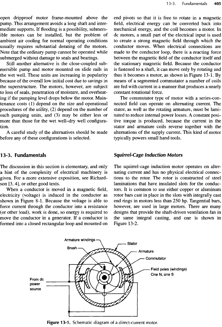
In
dc
motors,
a
small part
of the
electrical input
is
used
to
create
a
strong magnetic
field
through which
the
conductor moves. When
electrical
connections
are
made
to the
conductor loop, there
is a
reacting force
between
the
magnetic
field of the
conductor itself
and
the
stationary magnetic
field.
Because
the
conductor
is
fastened
to a
shaft,
it can
move only
by
rotating
and
thus
it
becomes
a
motor,
as
shown
in
Figure 13-1.
By
means
of a
segmented commutator
a
number
of
coils
are fed
with
current
in a
manner that produces
a
nearly
constant
rotational
force.
The
commutator type
of
motor with
a
series-con-
nected
field can
operate
on
alternating current.
The
stator,
as
well
as the
rotating armature, must
be
lami-
nated
to
reduce internal power losses.
A
constant posi-
tive
torque
is
produced, because
the
current
in the
stator
and
armature coils reverse together with
the
alternations
of the
supply current. This kind
of
motor
typically powers small hand
tools.
Squirrel-Cage
Induction
Motors
The
squirrel-cage induction motor operates
on
alter-
nating current
and has no
physical
electrical
connec-
tions
to the
rotor.
The
rotor
is
constructed
of
steel
laminations that have insulated slots
for the
conduc-
tors.
It is
common
to use
either copper
or
aluminum
rotor bars cast
in
place
in the
slots
with
integrally cast
end
rings
in
motors
less
than
250 hp.
Tangential
bars,
however,
are
used
in
large motors.
There
are
many
designs that provide
the
shaft-driven ventilation
fan in
the
same integral casting,
and one is
shown
in
Figure 13-2.
Figure
13-1.
Schematic
diagram
of a
direct-current
motor.
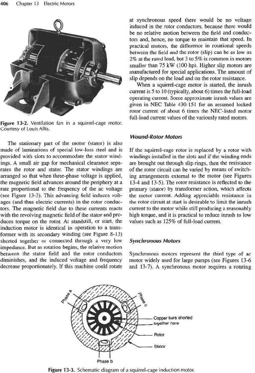
Figure
13-2.
Ventilation
fan in a
squirrel-cage
motor.
Courtesy
of
Louis
Al
I
is.
The
stationary part
of the
motor (stator)
is
also
made
of
laminations
of
special low-loss steel
and is
provided
with
slots
to
accommodate
the
stator wind-
ings.
A
small
air gap for
mechanical clearance sepa-
rates
the
rotor
and
stator.
The
stator windings
are
arranged
so
that when three-phase voltage
is
applied,
the
magnetic
field
advances around
the
periphery
at a
rate proportional
to the
frequency
of the ac
voltage
(see Figure 13-3). This advancing
field
induces volt-
ages (and thus electric currents)
in the
rotor conduc-
tors.
The
magnetic
field due to
these
currents
reacts
with
the
revolving magnetic
field of the
stator
and
pro-
duces
torque
on the
rotor.
At
standstill,
or
start,
the
induction
motor
is
identical
in
operation
to a
trans-
former
with
its
secondary winding (see Figure 8-13)
shorted together
or
connected through
a
very
low
impedance.
But as
rotation begins,
the
relative motion
between
the
stator
field and the
rotor conductors
diminishes,
and the
induced voltage
and
frequency
decrease proportionately.
If
this machine could rotate
at
synchronous speed there would
be no
voltage
induced
in the
rotor conductors, because there would
be no
relative motion between
the field and
conduc-
tors and, hence,
no
torque
to
maintain that speed.
In
practical motors,
the
difference
in
rotational speeds
between
the field and the
rotor (slip)
can be as low as
2%
at the
rated load,
but 3 to 5% is
common
in
motors
smaller than
75 kW
(100
hp). Higher slip motors
are
manufactured
for
special applications.
The
amount
of
slip depends
on the
load
and on the
rotor
resistance.
When
a
squirrel-cage motor
is
started,
the
inrush
current
is 5 to 10
(typically, about
6)
times
the
full-load
operating current. Some approximate inrush values
are
given
in NEC
Table
430-151
for an
assumed locked
rotor current
of
about
6
times
the
NEC-listed motor
full-load
current values
of the
variously rated motors.
Wound-Rotor
Motors
If
the
squirrel-cage rotor
is
replaced
by a
rotor with
windings
installed
in the
slots
and if the
winding ends
are
brought
out
through slip
rings,
then
the
resistance
of
the
rotor circuit
can be
varied
by
means
of
switch-
ing
arrangements external
to the
motor (see Figures
13-4
and
13-5).
The
rotor resistance
is
reflected
to the
primary
(stator)
by
transformer action, which
affects
the
motor current. Adding appreciable resistance
in
the
rotor circuit
at
start
is
desirable
to
limit
the
inrush
current
to the
motor while still producing
a
reasonably
high
torque,
and it is
practical
to
reduce inrush
to low
values
such
as
125%
of
full-load
current.
Synchronous
Motors
Synchronous motors represent
the
third type
of ac
motor widely used
for
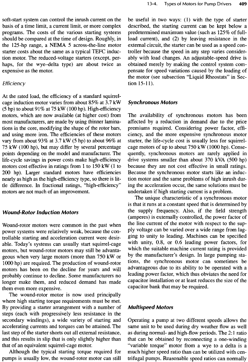
large pumps (see Figures 13-6
and
13-7).
A
synchronous motor requires
a
rotating
Figure
13-3.
Schematic diagram
of a
squirrel-cage
induction
motor.
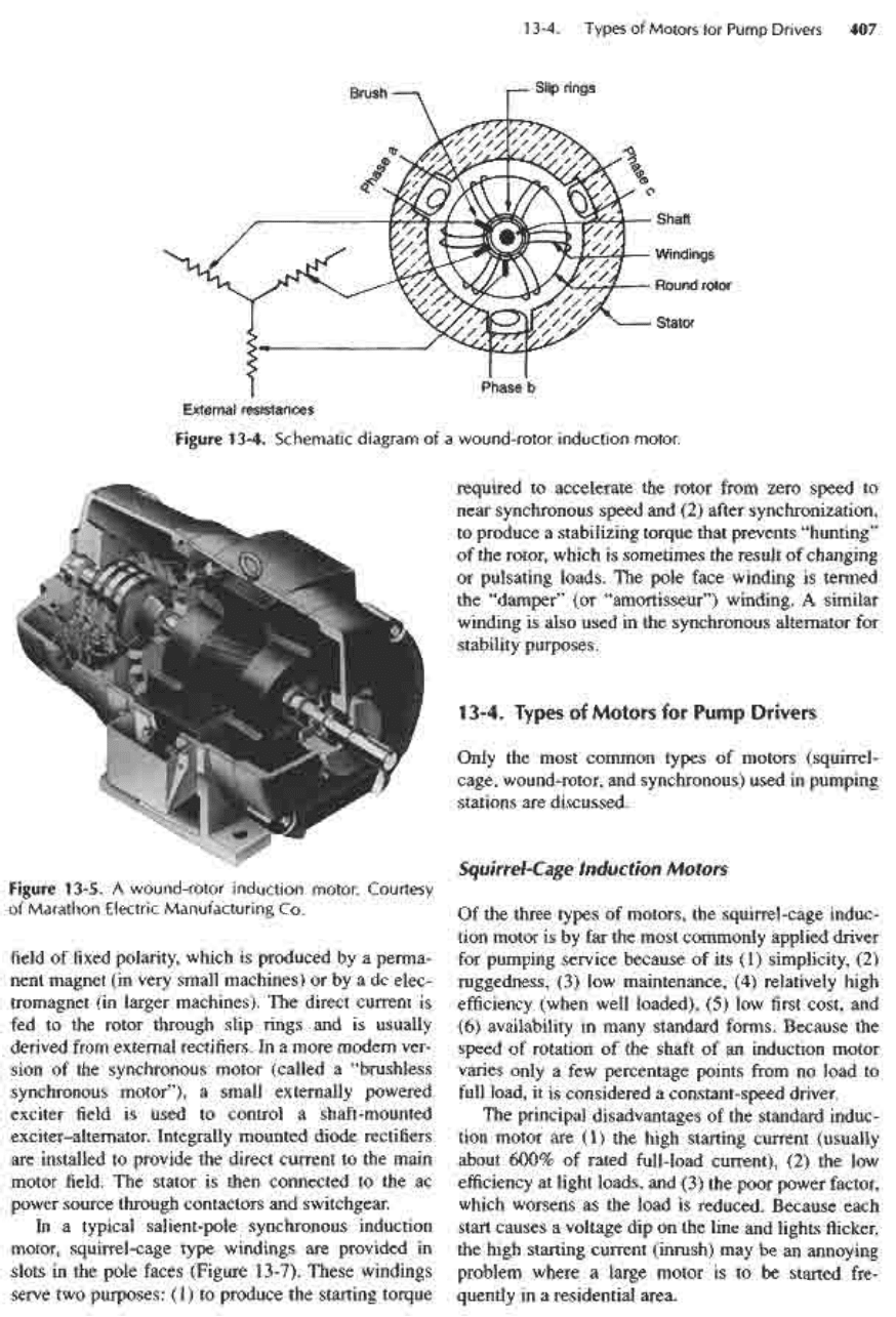
Figure
13-5.
A
wound-rotor
induction
motor.
Courtesy
of
Marathon
Electric Manufacturing
Co.
field
of
fixed
polarity, which
is
produced
by a
perma-
nent
magnet
(in
very small machines)
or by a dc
elec-
tromagnet
(in
larger machines).
The
direct current
is
fed
to the
rotor through slip rings
and is
usually
derived
from
external
rectifiers.
In a
more modern ver-
sion
of the
synchronous motor (called
a
"brushless
synchronous
motor"),
a
small externally powered
exciter
field is
used
to
control
a
shaft-mounted
exciter-alternator.
Integrally mounted diode rectifiers
are
installed
to
provide
the
direct current
to the
main
motor
field. The
stator
is
then connected
to the ac
power
source through contactors
and
switchgear.
In
a
typical salient-pole synchronous induction
motor, squirrel-cage type windings
are
provided
in
slots
in the
pole
faces
(Figure 13-7). These windings
serve
two
purposes:
(1)
to
produce
the
starting torque
required
to
accelerate
the
rotor
from
zero speed
to
near synchronous speed
and (2)
after
synchronization,
to
produce
a
stabilizing torque that prevents
"hunting"
of
the
rotor, which
is
sometimes
the
result
of
changing
or
pulsating loads.
The
pole
face
winding
is
termed
the
"damper"
(or
"amortisseur")
winding.
A
similar
winding
is
also used
in the
synchronous alternator
for
stability purposes.
1
3-4.
Types
of
Motors
for
Pump
Drivers
Only
the
most common types
of
motors (squirrel-
cage, wound-rotor,
and
synchronous) used
in
pumping
stations
are
discussed.
Squirrel-Cage
Induction
Motors
Of
the
three types
of
motors,
the
squirrel-cage induc-
tion motor
is by far the
most commonly applied driver
for
pumping service because
of its
(1)
simplicity,
(2)
ruggedness,
(3) low
maintenance,
(4)
relatively high
efficiency
(when well loaded),
(5) low first
cost,
and
(6)
availability
in
many standard forms. Because
the
speed
of
rotation
of the
shaft
of an
induction motor
varies only
a few
percentage points
from
no
load
to
full
load,
it is
considered
a
constant-speed driver.
The
principal disadvantages
of the
standard induc-
tion motor
are (1) the
high starting current (usually
about
600%
of
rated
full-load
current),
(2) the low
efficiency
at
light loads,
and (3) the
poor power
factor,
which
worsens
as the
load
is
reduced. Because each
start causes
a
voltage
dip on the
line
and
lights
flicker,
the
high starting current (inrush)
may be an
annoying
problem where
a
large motor
is to be
started fre-
quently
in a
residential area.
Figure
13-4.
Schematic diagram
of a
wound-rotor
induction
motor.
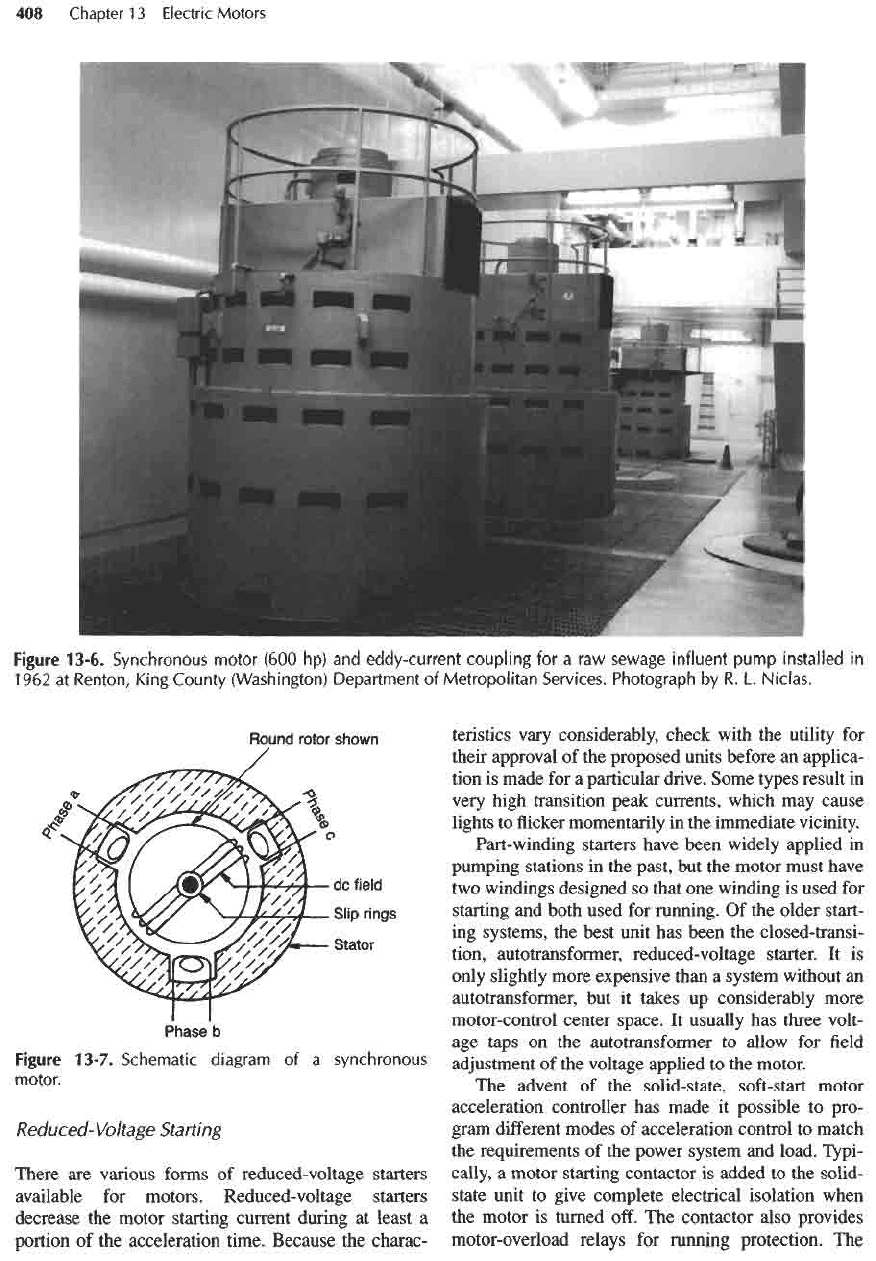
Figure
13-7.
Schematic diagram
of a
synchronous
motor.
Reduced-Voltage Starting
There
are
various
forms
of
reduced-voltage starters
available
for
motors.
Reduced-
voltage
starters
decrease
the
motor starting current during
at
least
a
portion
of the
acceleration time. Because
the
charac-
teristics vary considerably, check
with
the
utility
for
their approval
of the
proposed units before
an
applica-
tion
is
made
for a
particular drive. Some types result
in
very
high transition peak currents, which
may
cause
lights
to flicker
momentarily
in the
immediate vicinity.
Part-winding starters have been widely applied
in
pumping
stations
in the
past,
but the
motor must have
two
windings designed
so
that
one
winding
is
used
for
starting
and
both used
for
running.
Of the
older start-
ing
systems,
the
best unit
has
been
the
closed-transi-
tion,
autotransformer,
reduced-voltage starter.
It is
only
slightly more expensive than
a
system without
an
autotransformer,
but it
takes
up
considerably more
motor-control center space.
It
usually
has
three volt-
age
taps
on the
autotransformer
to
allow
for field
adjustment
of the
voltage applied
to the
motor.
The
advent
of the
solid-state,
soft-start
motor
acceleration controller
has
made
it
possible
to
pro-
gram
different
modes
of
acceleration control
to
match
the
requirements
of the
power system
and
load. Typi-
cally,
a
motor starting contactor
is
added
to the
solid-
state unit
to
give complete
electrical
isolation when
the
motor
is
turned off.
The
contactor also provides
motor-overload relays
for
running protection.
The
Figure
13-6. Synchronous motor (600
hp) and
eddy-current
coupling
for a raw
sewage
influent
pump installed
in
1962
at
Renton,
King County (Washington) Department
of
Metropolitan
Services.
Photograph
by R. L.
Niclas.
soft-start
system
can
control
the
inrush current
on the
basis
of a
time limit,
a
current limit,
or
more complex
programs.
The
costs
of the
various starting systems
should
be
compared
at the
time
of
design. Roughly,
in
the
125-hp
range,
a
NEMA
5
across-the-line
motor
starter costs about
the
same
as a
typical
TEFC
induc-
tion motor.
The
reduced-voltage starters (except, per-
haps,
for the
wye-delta
type)
are
about twice
as
expensive
as the
motor.
Efficiency
At
the
rated load,
the
efficiency
of a
standard squirrel-
cage induction motor varies
from
about
85% at 3.7 kW
(5
hp) to
about
91% at 75 kW
(100 hp).
High-efficiency
motors, which
are now
available
(at
higher cost)
from
most manufacturers,
are
made
by
using thinner lamina-
tions
in the
core,
modifying
the
shape
of the
rotor bars,
and
using more iron.
The
efficiencies
of
these motors
vary
from
about
93% at 3.7 kW (5 hp) to
about
96% at
75 kW
(100 hp),
but may
differ
by
several percentage
points
depending
on the
model
and
manufacturer.
The
life-cycle
savings
in
power costs make
high-efficiency
motors cost
effective
in
ratings
from
1 to 150 kW (1 to
200
hp). Larger standard motors have
efficiencies
nearly
as
high
as the
high-efficiency
type,
so
there
is
lit-
tle
difference.
In
fractional ratings, "high-efficiency"
motors
are not
much
of an
improvement.
Wound-Rotor
Induction Motors
Wound-rotor
motors were common
in the
past when
power systems were relatively weak, because
the
con-
trollable starting
and
acceleration current were desir-
able. Today's systems
can
usually start squirrel-cage
motors,
but
wound-rotor motors
may
still
be
advanta-
geous when very large motors (more than
750 kW or
1000
hp) are
required.
The
production
of
wound-rotor
motors
has
been
on the
decline
for
years
and
will
probably
continue
to
decline. Some manufacturers
no
longer make them,
and
reduced demand
has
made
them
even more expensive.
The
wound-rotor motor
is now
used principally
where
high starting torque requirements must
be
met.
By
providing
a
starter arrangement with
a
number
of
steps
(each with progressively less resistance
in the
secondary windings),
a
wide variety
of
starting
and
accelerating currents
and
torques
can be
attained.
The
last step
of the
starter shorts
out all
external resistance,
and
this results
in
slip that
is
only slightly higher than
that
of an
equivalent squirrel-cage motor.
Although
the
typical starting torque required
for
pumps
is
usually low,
the
wound-rotor motor
can
still
be
useful
in two
ways:
(1)
with
the
type
of
starter
described,
the
starting current
can be
kept below
a
predetermined
maximum value (such
as
125%
of
full-
load current),
and (2) by
leaving resistance
in the
external circuit,
the
starter
can be
used
as a
speed con-
troller
because
the
speed
in any
step varies
consider-
ably
with load changes.
An
adjustable-
speed
drive
is
obtained merely
by
making
the
control system com-
pensate
for
speed variations caused
by the
loading
of
the
motor (see subsection "Liquid
Rheostats"
in
Sec-
tion
15-11).
Synchronous Motors
The
availability
of
synchronous motors
has
been
affected
by a
reduction
in
demand
due to the
price
premiums required. Considering power factor,
effi-
ciency,
and the
more expensive synchronous motor
starter,
the
life-cycle cost
is
usually less
for
squirrel-
cage motors
of up to
about
750 kW
(1000 hp). Conse-
quently,
synchronous motors
are
rarely applied
in
drive systems smaller than about
370 kVA
(500
hp)
because they
are not
cost
effective
in
small ratings.
Because
the
synchronous motor starts
like
an
induc-
tion motor
and the
same problems
of
high inrush dur-
ing
the
acceleration occur,
the
same solutions must
be
undertaken
if
high starting current
is a
problem.
The
unique characteristic
of a
synchronous motor
is
that
it
runs
at a
constant speed that
is
determined
by
the
supply frequency. Also,
if the field
strength
(amperes)
is
externally controlled,
the
power factor
of
the
line current
of the
motor with respect
to the
sup-
ply
voltage
can be
varied over
a
wide range
from
lag-
ging
to
unity
to
leading. Machines
can be
specified
with
unity, 0.8,
or 0.6
leading power factors,
for
which
the
suitable machine current rating
is
provided
by
the
manufacturer's design.
In
large pumping sta-
tions,
the
synchronous motor
can
sometimes
be
advantageous
due to its
ability
to be
operated with
a
leading power factor, which thus obviates
the
need
for
capacitor installation
or at
least reduces
the
size
of the
capacitor bank that
may be
required.
Multispeed
Motors
Operating
a
pump
at two
different
speeds allows
the
same unit
to be
used during
dry
weather
flow as
well
as
during normal-
and
high-flow
periods.
The
2:
1
ratio
that
can be
obtained
by
reconnecting
a
one-winding
"variable
torque"
motor
from
a wye to a
delta
is a
much
higher speed ratio than
can be
utilized with cen-
trifugal
pumps. Reasonable speed ratios
can
normally
be
obtained with
a
two-speed, two-winding arrange-
ment.
For
example,
one
winding
may
provide
a
four-
pole speed
of
1800
rev/min
while
the
other provides
a
six-pole speed
of
1200
rev/min with
a
speed ratio
of
3:2. Closer ratios
may be
obtained
by
using
a
lower
base speed, such
as
1200
or 900
rev/min.
Constant-
and
Adjustable-Speed
Systems
There
are
many ways
to
provide speed-control devices
for
constant-speed motors, including:
•
Direct current drivers
with
field
control
•
Wound-rotor induction motors with rotor circuit
resistance control (controlled slip)
•
Variable-pitch sheaves
•
Hydraulic couplings that produce controlled slip
•
Eddy-current couplings
that
provide controlled slip
within
the
coupling
•
Hydraulic pump/motor combinations
•
Adjustable-frequency
drives.
All
of the
slip-producing devices, except
the
expen-
sive
wound-rotor slip-recovery system, result
in
con-
siderable energy loss.
In
contrast,
the
energy losses
in
the
adjustable-frequency
and
direct current drives
are
low.
Reducing
the
speed
of the
pump
by
whatever
means, however,
often
entails
a
loss
of
hydraulic
effi-
ciency unless
the
pump
is
selected according
to the
principles explained
in
Chapter
15, in
which variable-
and
adjustable-speed systems
are
discussed
at
length.
13-5. Characteristics
of
Squirrel-Cage
Induction
Motors
A
number
of
designs that have
significantly
differing
starting
current
and
torque characteristics
are
listed
by
NEMA.
The two
most
useful
in
pumping stations
are
Design
B and
Design
D
motors. Design
B is
termed
"normal
starting torque, normal starting current,
and
normal
slip."
This
is the
most commonly applied
motor design
and is
generally used
for
driving centrif-
ugal pumps,
fans,
blowers, compressors with unload-
ing
start controls,
and
machine tools.
The
normal slip
at
full
load
is
approximately
3 to 5%, and the
starting
current varies
from
500 to
600%.
Design
D is
termed "high starting torque, normal
starting current,
and
high
slip."
The
rotor
in
Design
D
has
a
higher resistance than
the
rotor
in
Design
B.
The
high
resistance
in the
rotor produces high starting
torque,
but it
also causes high slip
(5 to 8% or
even
8
to
13%)
at
full
load;
the
inrush current
is the
same
as
for
Design
B.
High slip
in
Design
D
causes greater
internal loss
and,
therefore, less
efficiency.
Neverthe-
less, hard-starting loads (such
as
reciprocating pumps
and
progressive cavity pumps)
may
require
a
high-slip
motor
for
satisfactory starting.
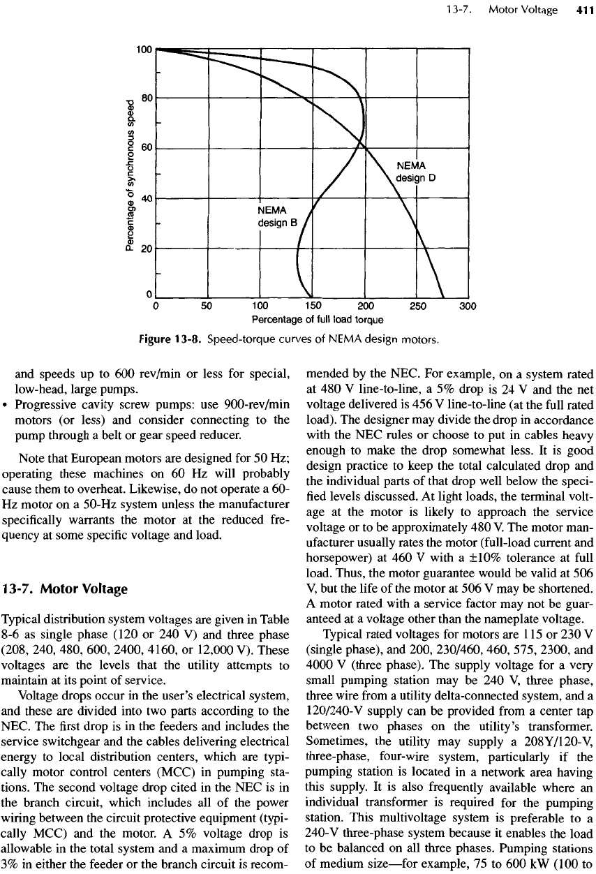
A
typical
set of
torque
curves
for
various standard designs
is
shown
in
Figure
13-8.
Manufacturers
can
frequently provide special
designs
to
match
a
particular loading characteristic,
but
that
may
mean delayed delivery
and
troublesome
replacement problems.
13-6. Motor Speed
The
speed
of the
rotor depends
on the
speed
of
rota-
tion
of the
magnetic
field
produced
by the
stator
cur-
rents.
The
conductors
can be
wound
in the
stator slots
to
produce
any
desired number
of
resultant north-
south
pole pairs around
the
periphery
of the
stator.
One
pair
of
poles
in a
three-phase winding
is
illus-
trated
in
Section
13-3.
One
cycle
of
sinusoidal alter-
nating current represents
360
electrical degrees
and
during this time
the
magnetic
field
rotates
360
mechanical degrees
or
completely around
the
stator.
Because
60 Hz ac
produces
60
revolutions
of the field
per
second
(or
3600
rev/min),
a
one-pole pair machine
(commonly termed
a
two-pole machine) rotates
3600
rev/min
at
zero slip.
An
equation
for
synchronous
speed
in SI
units
is
co
=
2
*^
(13-1.)
where
co is
radians
per
second,
Hz is
current
frequency
in
cycles
per
second,
and n is the
number
of
poles
(which
is
twice
the
number
of
pole pairs).
In
U.S. cus-
tomary units
co
=
120
<"*>
(13-lb)
where
co is
revolutions
per
minute
and the
other terms
are as
defined
above.
Preferred motor speeds
for
pumping station equip-
ment depend
on the
characteristics
of the
driven
equipment
as
well
as the
overall
costs
—
in
particular,
the
life-cycle costs
of the
various practical alternative
speeds.
As a
general recommendation,
the
following
guidelines apply
to
pumping station equipment:
•
Blowers
and
fans:
use
1800-
or
3600-rev/min
motors with speed increaser gears when higher
speeds
are
required. Note, however, that high speed
produces
a
high noise level.
•
Water, sewage,
or
sludge pumping:
use
900-,
1200-,
or
1800-rev/min
motors
for
medium
to
small pumps
and
speeds
up to 600
rev/min
or
less
for
special,
low-head, large pumps.
•
Progressive cavity screw pumps:
use
900-rev/min
motors
(or
less)
and
consider connecting
to the
pump
through
a
belt
or
gear speed reducer.
Note that European motors
are
designed
for 50 Hz;
operating these machines
on 60 Hz
will probably
cause them
to
overheat. Likewise,
do not
operate
a 60-
Hz
motor
on a
50-Hz
system unless
the
manufacturer
specifically
warrants
the
motor
at the
reduced fre-
quency
at
some
specific
voltage
and
load.
13-7.
Motor
Voltage
Typical
distribution system voltages
are
given
in
Table
8-6 as
single phase
(120
or 240 V) and
three phase
(208, 240, 480, 600,
2400,
4160,
or
12,000
V).
These
voltages
are the
levels that
the
utility attempts
to
maintain
at its
point
of
service.
Voltage
drops occur
in the
user's electrical system,
and
these
are
divided into
two
parts according
to the
NEC.
The first
drop
is in the
feeders
and
includes
the
service switchgear
and the
cables delivering electrical
energy
to
local distribution centers, which
are
typi-
cally motor control centers (MCC)
in
pumping sta-
tions.
The
second voltage drop cited
in the NEC is in
the
branch circuit, which includes
all of the
power
wiring
between
the
circuit protective equipment (typi-
cally MCC)
and the
motor.
A 5%
voltage drop
is
allowable
in the
total system
and a
maximum drop
of
3%
in
either
the
feeder
or the
branch circuit
is
recom-
mended
by the
NEC.
For
example,
on a
system rated
at
480 V
line-to-line,
a 5%
drop
is 24 V and the net
voltage delivered
is 456 V
line-to-line
(at the
full
rated
load).
The
designer
may
divide
the
drop
in
accordance
with
the NEC
rules
or
choose
to put in
cables heavy
enough
to
make
the
drop somewhat less.
It is
good
design practice
to
keep
the
total calculated drop
and
the
individual parts
of
that drop well below
the
speci-
fied
levels
discussed.
At
light loads,
the
terminal volt-
age
at the
motor
is
likely
to
approach
the
service
voltage
or to be
approximately
480 V. The
motor man-
ufacturer
usually rates
the
motor
(full-load
current
and
horsepower)
at 460 V
with
a
±10% tolerance
at
full
load. Thus,
the
motor guarantee would
be
valid
at 506
V,
but the
life
of the
motor
at 506 V may be
shortened.
A
motor rated with
a
service
factor
may not be
guar-
anteed
at a
voltage other than
the
nameplate voltage.
Typical
rated voltages
for
motors
are
115
or 230 V
(single phase),
and
200,
230/460,
460, 575,
2300,
and
4000
V
(three phase).
The
supply voltage
for a
very
small pumping station
may be 240 V,
three phase,
three wire
from
a
utility
delta-connected system,
and a
120/240-
V
supply
can be
provided
from
a
center
tap
between
two
phases
on the
utility's transformer.
Sometimes,
the
utility
may
supply
a
208Y/120-V,
three-phase, four-wire system, particularly
if the
pumping station
is
located
in a
network area having
this
supply.
It is
also frequently available where
an
individual transformer
is
required
for the
pumping
station. This
multivoltage
system
is
preferable
to a
240-V
three-phase system because
it
enables
the
load
to
be
balanced
on all
three phases. Pumping stations
of
medium
size
—
for
example,
75 to 600 kW
(100
to
Figure
13-8. Speed-torque curves
of
NEMA design motors.
800
hp)
—
need
a
full
480-V supply
and
usually derive
their
own
1
20-
V
circuits
for
lighting, small power out-
lets,
and
control devices
from
dry-type transformers
located
in the
station.
Ordinarily,
the
service
for a
large station
is
most
economical
at the
highest voltage available,
and
large
pumping
stations require
4
160-
V
service. Because
motors
are
usually rated
at
4000
V
maximum, however,
there
is no
advantage
in
utility service above 4160
V
unless
the
utility
rate schedule
for
higher voltage ser-
vice
is
particularly appealing
to the
owner. Higher ser-
vice voltage
in
such situations would reduce cable size
for
power distribution,
but
transformers would
be
required
to
provide
an
operating voltage
of
4160
or
less,
and
they
are
costly. Note that some 230-V motors
are
guaranteed
by the
manufacturer
for
operation
on
208 V, but
some manufacturers then
qualify
this rating
as
not
necessarily meeting NEMA standards.
There-
fore,
use
200-V motors
for
208-V systems.
A
study
of
alternative voltage levels
and
sources
should precede
the
selection
of
both service voltage
and
utilization voltage.
For
example,
480 V is
nearly
always
the
preferred
and
most economical level
for
both service
and
distribution
in
medium-sized pump-
ing
stations
with
short feeders
and
service runs. How-
ever,
if the
cable
run
from
the
service point
to
the-
pumping
plant
is,
say,
15Om
(500
ft) or
longer,
the
excessive cable costs
at 480 V can
make
2400-
or
4
160-
V
service more economical.
The
cost
of
in-plant
transformers
versus utility-furnished transformers
should
be
studied
carefully
on a
life-cycle basis.
Service
from
a
utility circuit
is
usually obtained
through pole-mounted
fuses,
but in the
largest sta-
tions, service
may be
obtained
from
a
utility circuit
breaker.
In
addition
to the
loading recommendations
given
here, make sure that
the
utility provides
a
bal-
anced system voltage
of
rated value.
In
addition,
require overload relays
in
each phase
of the
motor
branch circuit
to
remove
the
motor
from
operation
in
the
event
of
"single-phasing" (which occurs when
a
fuse
on one leg
blows).
The
prevention
of
single
-phas-
ing
begins
in the
utility's system
and
carries
through-
out
the
pumping station electrical system.
Wherever single-pole switching equipment
is
used,
install current-balance relays
and
circuit breakers with
interpole
tripping
to cut
station power
in the
event
of
an
unbalance greater than
the
relay setting allows.
Never
install circuit breaker handle ties even
in the
smallest stations. Some unbalance
is
always present
due
to
lighting
or
single-phase auxiliary equipment,
and
the
current-balance relays must
be set to
accom-
modate this unbalance.
If
single-phase loads
are
large
enough
to
cause voltage unbalance, distribute these
loads between
the
phases
as
equally
as
possible.
Voltage
unbalance causes excessive heating
of
motors.
A 2%
unbalance, according
to
IEEE
Standard
141,
adds about
8% to the
heat
in the
motor windings
and
causes
the
temperature
to rise
from
80 to
86.4
0
C.
A
3.5% unbalance causes
an
approximate
25%
increase
in
heating,
so the
temperature
rises (in a
Class
B
insu-
lation,
T-frame
motor)
from
80 to
10O
0
C.
13-8.
Enclosures
The
motor enclosure provides
the
environmental pro-
tection
for the
motor,
a
mounting space
for the
stator
windings,
the
magnetic circuit
for the
stator
field, a
ventilation space,
and a
mounting
for the
bearings
on
most models. Motor enclosures, which
are
defined
in
Section
13-1,
are
•
Dripproof
•
Splashproof
(if not
available, substitute weather
protected
Type
I)
•
Totally enclosed (TE)
•
Totally enclosed, fan-cooled (TEFC)
•
Totally enclosed, nonventilated (TENV)
•
Totally enclosed, pipe-ventilated
•
Weather-protected, Types
I and II
•
Submersible
•
Explosionproof.
The
open dripproof
and
totally
enclosed
fan-
cooled
enclosures
are the
ones most commonly used
in
pumping stations. Small-
to
medium-sized open
motors
may
have
epoxy-encapsulated
windings,
and
they
give excellent performance
in
quite severe condi-
tions. They
are the
least expensive
to put
back into
service
in the
event
of flooding.
Nonencapsulated
dripproof motors
are not
usually applicable
for
pump-
ing
station environments. Horizontal machines
are
particularly vulnerable
to
hosing-down operations.
The
totally
enclosed
fan-cooled motor usually
has
the fan
mounted integrally with
the
motor under
a
shrouded-end
bell
arrangement.
Air is
drawn into
the
end of the
motor
and
distributed over
the
outside
of
the
motor enclosure
by the
fan.
The
cooling ability
of
a
TEFC
motor
is
less than that
of a
similar open drip-
proof motor.
The
TEFC
motor
may be
used
in
both
indoor
and
outdoor environments. Horizontal
TEFC
motors should
be
provided with drain holes
or a
breather drain
in the
bottom
of the
enclosure
to
permit
the
escape
of
condensation should
it
collect inside
the
enclosure.
The
shaft,
of
course, extends through
and
beyond
the
enclosure.
The
totally enclosed, nonventilated motor
is
usu-
ally
used only
for
small, noncritical loads.
Totally enclosed pipe-ventilated
motors
are
likely
to be
used
in
adjustable-speed systems where,
at low
speeds,
insufficient
cooling would
be
available
from
the
ordinary shaft-mounted fan. This type
of
ventila-
tion
may
also
be
appropriate where
the
motor
is
sub-
jected
to
higher than normal ambient temperatures
but
where
cooler
air is
available.
Weather-protected Type
I
motors should always
be
considered
for
large drivers
in
ratings where
TEFC
is
not
a
standard option.
It is
also applied indoors
in
some installations where pipe breaks
may
spray
the
equipment.
Use
weather-protected Type
II
motors
in
outdoor
applications subject
to
high wind
and
rain.
Only
explosionproof motors
can be
used
in
areas
that
are
classified
as
Class
1,
Division
1
hazardous
locations
in
Article
500 of the
NEC. These motors
are
similar
to the
TEFC
in
cooling,
but are
much
more
expensive
than
the
TEFC motor.
Submersible
motors
are
often
used
in
water wells
and in
many sewage pumping stations. Most models
must
be
totally
submerged
to
cool properly,
and
because
the
motors
are
"ordinarily"
submerged,
a
sub-
mersible rating
is
adequate.
In the
event
of a
malfunc-
tion
and
subsequent overheating combined with
possible explosive
gas
accumulation
in the
manhole,
however,
an
extreme hazard
may be
created. Some
motors
can be run
intermittently
or
continuously
in
air.
For
additional discussion,
see
Section 13-2
and
Chapter
25.
13-9.
Insulation
Motor windings,
by
necessity,
are
closely packed into
slots that
are
designed
to
accommodate them.
The
methods used
to
maintain
conductor-
to-metal,
con-
ductor-to-conductor,
and
phase-to-phase insulation
vary
greatly depending
on the
size
and
application
of
the
motor. Pumping station designers
and
motor spec-
ifiers
are
more concerned with
the
class
of
insulation
than
with
the
details
of
packaging.
In
addition
to
other considerations,
the
type
of
insulation
that should
be
specified
for a
pump driver
motor depends
on its
suitability
in a
possibly moist
atmosphere,
its
ability
to be
dried readily
in the
event
of
a
submersion,
and the
ambient temperature condi-
tions
that
will
prevail
in its
location. Insulation
is
ordi-
narily
classified
by
letter designations that
infer
its
ability
to
withstand continuous
operation
at a
defined
total
temperature
(or
some
rise
above
a
standard ambi-
ent
temperature).
The
letter
designation
is
also
defined
in
terms
of the
types
of
materials used
in the
insula-
tion
system.
The
allowable
temperature
rises
above
a
4O
0
C
ambient
temperature
for the
various standard letter
designations
and
enclosure types (taken
from
NEMA
MG-
12.42)
are
summarized
in
Table 13-2.
All of the
temperatures
in
Table
13-2
are
measured
by
resistance
in
accordance with NEMA standards.
If the
ambient
temperature
is
higher than
4O
0
C,
a
berating equation
is
given
in
NEMA
MG-I
for the
allowable temperature
rise (see
the
latest revision
of
NEMA
MG-I).
The
insulation
materials
for the
several classes are:
•
Class
A:
Combinations
of
materials such
as
cotton,
silk,
and
paper impregnated
or
immersed
in a
dielectric liquid,
no
longer
specified
for
pumping
station applications
and now
encountered only
in
very
old
drivers
•
Class
B:
Combinations
of
materials such
as
mica,
glass
fiber,
asbestos,
and so on
with bonding sub-
stances
•
Class
F:
Similar
to
Class
B, but
designed
for a
higher operating temperature
at the
same thermal
life
•
Class
H:
Similar
to
Class
F,
except
for the use of
component materials (such
as
silicone elastomers)
rated
for a
higher operating temperature
at the
same
thermal
life.
Note that Class
H
insulation
may be
unavailable,
and its
thickness
causes
design prob-
lems.
Epoxy insulation
was
used
in the
past
to
permit
an
inundated
motor
to be put
into
service
almost immedi-
ately
after
the dry pit was
dewatered.
But
epoxy
is
short lived because
of the
cracks that develop.
Use
Class
F or H
insulation
and
take
the
time
to dry a
pre-
viously
submerged motor properly.
Although
thermal
life
is not
quantifiable
by
aging
time
alone,
modern insulations (Class
B, F, or H) can
be
expected
to
last
25 yrs at
conservative temperatures
unless
they
are
subject
to
extreme vibration
or
extreme thermal cycling.
Table
13-2.
Allowable
Temperature
Rise
for
Insulation
in
Motors
3
NEMA
insulation
letter
designation
Motor
enclosure
ABF
H
Totally
enclosed,
fan-cooled
60 80 105 125
Totally
enclosed,
nonventilated
65 85 110 135
Encapsulated
with LOSF
65 85 110 —
All
other
motors,
with 1.15
SF 70 90 115 —
All
other
motors
60 80 105 125
a
Degrees Celsius above
4O
0
C
ambient
from
NEMA
MG-I
Table
12.42.
1.4.
