Pumping Station Desing - Second Edition by Robert L. Sanks, George Tchobahoglous, Garr M. Jones
Подождите немного. Документ загружается.

engine room ventilation
air is filtered,
specify
dry-
type
filter
elements. Larger engines require
an air
intake system ducted outside
of the
building
to
avoid
upsetting
the
building ventilation system,
and the
pumping
station designer should
be
responsible
for
such
an air
intake system.
If
turbocharged engines
are
installed,
a
separate silencer
is
needed
to
control
intake noise.
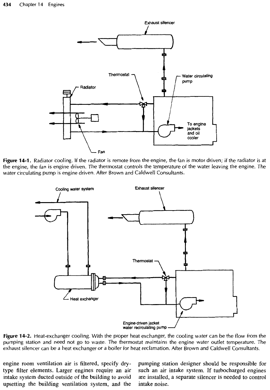
Figure
14-1.
Radiator
cooling.
If the
radiator
is
remote from
the
engine,
the fan is
motor
driven;
if the
radiator
is at
the
engine,
the fan is
engine
driven.
The
thermostat controls
the
temperature
of the
water leaving
the
engine.
The
water circulating
pump
is
engine driven. After Brown
and
Caldwell
Consultants.
Figure
14-2. Heat-exchanger
cooling.
With
the
proper heat exchanger,
the
cooling
water
can be the
flow
from
the
pumping
station
and
need
not go to
waste.
The
thermostat maintains
the
engine water outlet temperature.
The
exhaust
silencer
can be a
heat exchanger
or a
boiler
for
heat reclamation.
After
Brown
and
Caldwell
Consultants.
14-13.
Exhaust
Silencing
Exhaust silencers must
be
selected specifically
for the
application because
of
engine back-pressure limitations
and
should, therefore,
be
furnished
by the
engine manu-
facturer.
Chambered, ported types appear
to be the
best.
There
are
four
different
grades
of
effectiveness:
•
Industrial
—
minimal
sound attenuation
•
Commercial
—
suitable
for
nonresidential
areas
•
Residential
—
applications
where
a
high degree
of
silencing
is
required
•
Critical
—
maximum
silencing
for
locations near
hospitals
and
very quiet residential areas.
Do not
rely solely
on the
silencer manufacturer's
rating
for the
equipment. Instead, specify noise reduc-
tion
by
octave band.
In
critical
applications, specify
a
result, that
is, the
noise
level
on the
decibel-
A
scale
(dbA)
at a
specific distance
from
the
exhaust.
An
acoustical engineer should
be
consulted
in
such
instances (see also Chapter 22).
Because
of
their design, exhaust heat boilers provide
a
high degree
of
silencing
and
approach residential
quality. Specify inspection ports
and
drain plugs
for all
silencers
and for the gas
side
of all
exhaust heat boilers.
(Davited inspection doors
are
preferred
for
boilers.)
Stainless steel (type 347)
may be
advisable
for
silencers
serving engines that operate only intermittently.
14-14.
Pollution
Control
Federal regulations
and
many local
air
pollution control
codes require some
form
of
exhaust emission control.
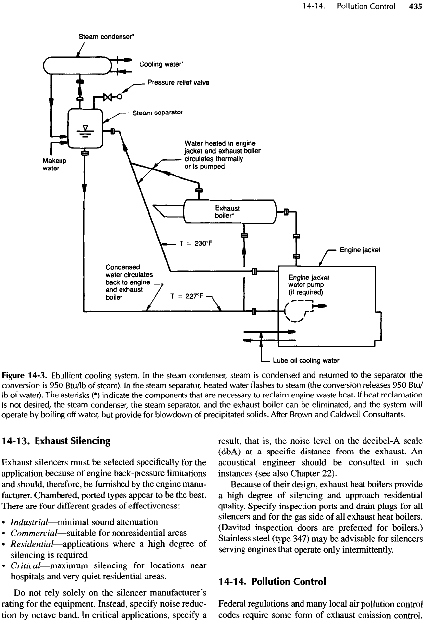
Figure 14-3. Ebullient
cooling
system.
In the
steam
condenser,
steam
is
condensed
and
returned
to the
separator (the
conversion
is 950
Btu/lb
of
steam).
In the
steam separator, heated water flashes
to
steam (the conversion releases
950
Btu/
Ib of
water).
The
asterisks
(*)
indicate
the
components
that
are
necessary
to
reclaim engine waste heat.
If
heat
reclamation
is
not
desired,
the
steam
condenser,
the
steam separator,
and the
exhaust
boiler
can be
eliminated,
and the
system
will
operate
by
boiling
off
water,
but
provide
for
blowdown
of
precipitated
solids.
After Brown
and
Caldwell
Consultants.
Pollutants
of
interest include
particulates,
and
oxides
of
sulfur
(SO
x
)
and
nitrogen
(NO
x
).
Many control technol-
ogies have
been
attempted
—
with
mixed
results.
Generally speaking, exhaust converters using
noble metal catalysts have
not
worked well even when
using
a
clean-burning
fuel
such
as
natural gas. Turbo-
charged engines, using
a
very lean mixture
in the
combustion chamber, have achieved better (but
not
reliable) performance.
The
reason
is
that many
of the
systems utilize sensors that
are
located
in
hostile envi-
ronments such
as
combustion chambers
and
exhaust
gas
streams,
and
they depend
on
sensitive instrumen-
tation
systems. Maintenance costs
are
high because
of
the
labor required
to
keep
the
equipment properly
tuned
for
optimum emission performance.
Emerging technologies using parameters easily
measured outside
the
combustion chamber
and
exhaust
gas
stream, such
as
fuel
charge temperature
and
pres-
sure, engine torque,
and so on,
promise improved per-
formance
and
reduced maintenance costs. Some
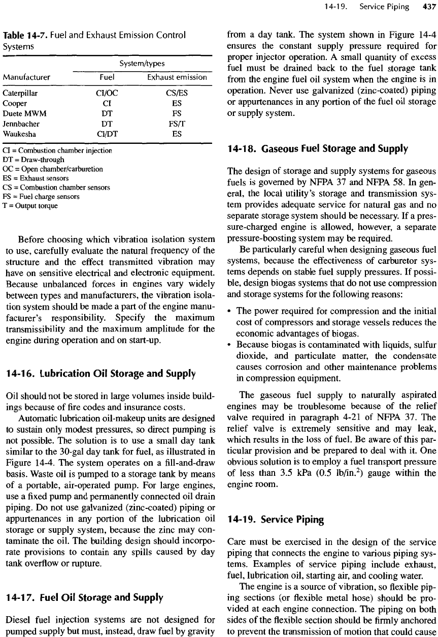
guidance regarding current (January 1996) emission
control technology used
by
various manufacturers
of
turbocharged
engines
is
given
in
Table
14-7.
14-15.
Vibration
Isolation
Depending
on the
application,
the
subsoil conditions,
and
the
nature
of the
building housing
the
engines,
the
following
alternatives
can be
used
to
isolate engine
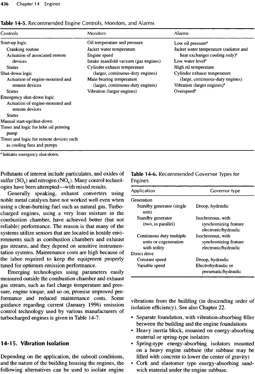
Table
14-6.
Recommended
Governor
Types
for
Engines
Application
Governor type
Generation
Standby
generator (single Droop, hydraulic
unit)
Standby
generator Isochronous, with
(two,
in
parallel) synchronizing
feature
electronic/hydraulic
Continuous
duty
multiple Isochronous, with
units
or
cogeneration synchronizing
feature
with
utility
electronic/hydraulic
Direct drive
Constant
speed Droop, hydraulic
Variable
speed Electrohydraulic
or
pneumatic/hydraulic
vibrations
from
the
building
(in
descending
order
of
isolation
efficiency).
See
also Chapter
22.
•
Separate foundation, with vibration-absorbing
filler
between
the
building
and the
engine foundations
•
Heavy
inertia
block,
mounted
on
energy-absorbing
material
or
spring-type
isolators
•
Spring-type energy-absorbing isolators mounted
on
a
heavy engine subbase (the subbase
may be
filled
with
concrete
to
lower
the
center
of
gravity)
•
Cork
and
elastomer type energy-absorbing sand-
wich
material under
the
engine subbase.
Controls
Start-up
logic
Cranking
routine
Actuation
of
associated remote
devices
Status
Shut-down
logic
Actuation
of
engine-mounted
and
remote
devices
Status
Emergency
shut-down logic
Actuation
of
engine-mounted
and
remote devices
Status
Manual
start-up/shut-down
Timer
and
logic
for
lube
oil
priming
pump
Timer
and
logic
for
remote devices
such
as
cooling
fans
and
pumps
a
Initiates
emergency
shut-down.
Monitors
Oil
temperature
and
pressure
Jacket
water temperature
Engine speed
Intake
manifold
vacuum
(gas engines)
Cylinder
exhaust temperature
(larger,
continuous-duty engines)
Main
bearing temperature
(larger, continuous-duty engines)
Vibration
(larger engines)
Alarms
Low
oil
pressure
3
Jacket
water temperature (radiator
and
heat
exchanger cooling
only)
a
Low
water
level
8
High
oil
temperature
Cylinder exhaust temperature
(large,
continuous-duty engines)
Vibration
(larger
engines)
a
Overspeed
a
Table 14-5.
Recommended
Engine
Controls,
Monitors,
and
Alarms
Table
14-7.
Fuel
and
Exhaust
Emission
Control
Systems
System/types
Manufacturer
Fuel
Exhaust
emission
Caterpillar
CI/OC
CSfES
Cooper
CI ES
Duete
MWM DT FS
Jennbacher
DT
FS/T
Waukesha
CI/DT
ES
CI
=
Combustion chamber injection
DT =
Draw-through
OC =
Open
chamber/carburetion
ES =
Exhaust sensors
CS
=
Combustion chamber sensors
FS =
Fuel
charge
sensors
T =
Output
torque
Before
choosing which vibration isolation system
to
use,
carefully
evaluate
the
natural frequency
of the
structure
and the
effect
transmitted vibration
may
have
on
sensitive electrical
and
electronic equipment.
Because unbalanced forces
in
engines vary widely
between types
and
manufacturers,
the
vibration isola-
tion
system should
be
made
a
part
of the
engine manu-
facturer's
responsibility.
Specify
the
maximum
transmissibility
and the
maximum amplitude
for the
engine during operation
and on
start-up.
14-16.
Lubrication
Oil
Storage
and
Supply
Oil
should
not be
stored
in
large volumes inside build-
ings
because
of fire
codes
and
insurance costs.
Automatic
lubrication oil-makeup units
are
designed
to
sustain only modest
pressures,
so
direct pumping
is
not
possible.
The
solution
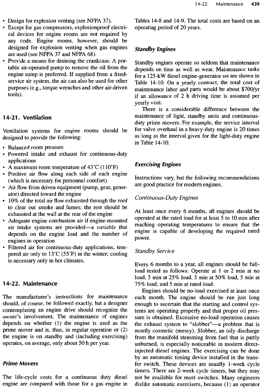
is to use a
small
day
tank
similar
to the
30-gal
day
tank
for
fuel,
as
illustrated
in
Figure 14-4.
The
system operates
on a fill-and-draw
basis. Waste
oil is
pumped
to a
storage tank
by
means
of
a
portable, air-operated pump.
For
large
engines,
use
a fixed
pump
and
permanently connected
oil
drain
piping.
Do not use
galvanized (zinc-coated) piping
or
appurtenances
in any
portion
of the
lubrication
oil
storage
or
supply system, because
the
zinc
may
con-
taminate
the
oil.
The
building design should incorpo-
rate provisions
to
contain
any
spills caused
by day
tank
overflow
or
rupture.
14-17.
Fuel
Oil
Storage
and
Supply
Diesel
fuel
injection systems
are not
designed
for
pumped supply
but
must, instead, draw
fuel
by
gravity
from
a day
tank.
The
system shown
in
Figure 14-4
ensures
the
constant supply pressure required
for
proper injector operation.
A
small quantity
of
excess
fuel
must
be
drained back
to the
fuel
storage tank
from
the
engine
fuel
oil
system when
the
engine
is in
operation. Never
use
galvanized (zinc-coated) piping
or
appurtenances
in any
portion
of the
fuel
oil
storage
or
supply system.
14-18.
Gaseous
Fuel
Storage
and
Supply
The
design
of
storage
and
supply systems
for
gaseous
fuels
is
governed
by
NFPA
37 and
NFPA
58. In
gen-
eral,
the
local utility's storage
and
transmission sys-
tem
provides adequate service
for
natural
gas and no
separate storage system should
be
necessary.
If a
pres-
sure-charged engine
is
allowed, however,
a
separate
pressure-boosting system
may be
required.
Be
particularly
careful
when designing gaseous
fuel
systems,
because
the
effectiveness
of
carburetor sys-
tems depends
on
stable
fuel
supply pressures.
If
possi-
ble, design biogas systems that
do not use
compression
and
storage systems
for the
following reasons:
• The
power required
for
compression
and the
initial
cost
of
compressors
and
storage vessels reduces
the
economic advantages
of
biogas.
•
Because biogas
is
contaminated with liquids,
sulfur
dioxide,
and
particulate
matter,
the
condensate
causes corrosion
and
other maintenance problems
in
compression equipment.
The
gaseous
fuel
supply
to
naturally aspirated
engines
may be
troublesome because
of the
relief
valve required
in
paragraph 4-21
of
NFPA
37. The
relief
valve
is
extremely
sensitive
and may
leak,
which
results
in the
loss
of
fuel.
Be
aware
of
this par-
ticular provision
and be
prepared
to
deal with
it. One
obvious solution
is to
employ
a
fuel
transport pressure
of
less than
3.5
kPa
(0.5
lb/in.
2
)
gauge within
the
engine room.
1
4-1
9.
Service
Piping
Care must
be
exercised
in the
design
of the
service
piping that connects
the
engine
to
various piping sys-
tems. Examples
of
service piping include exhaust,
fuel,
lubrication oil, starting air,
and
cooling water.
The
engine
is a
source
of
vibration,
so flexible
pip-
ing
sections
(or flexible
metal hose) should
be
pro-
vided
at
each engine connection.
The
piping
on
both
sides
of the flexible
section should
be firmly
anchored
to
prevent
the
transmission
of
motion that could cause
the
joints
or flexible
hoses
to
fail.
Also observe
the
following
considerations:
•
Install
the flexible
hose
as
close
as
possible
to the
exhaust
outlet.
•
Avoid
fittings or
lengths
of
pipe between
the
engine
exhaust
connection
and the flexible
hose;
the
weight
could damage
the
exhaust manifold.
• Try to
make
flexible
piping connections
as
close
as
possible
to the
engine crankshaft.
•
Install
flexible
sections parallel
to the
engine crank-
shaft
to
increase their service
life.
•
Require
flexible
piping sections
to be
designed
for a
specific
number
of
full
displacement cycles
(10,000,000
is
suggested).
•
Install isolating valves
and
automatically controlled
valves,
such
as
fuel
and air
valves,
in the
rigid
gas
piping upstream
from
any
pressurized
flexible
sec-
tion
to
avoid
the
escape
of
fuel
to the
engine room
if
the flexible
section
fails.
• Use
braided stainless-steel hose rated
for a
working
pressure
at
least twice
as
great
as the
system's max-
imum
pressure.
•
Provide
flexible
duct connectors between engine-
mounted radiators
and
built-in exhaust louvers.
14-20.
Building
Envelope
When designing structures
for
engine installations,
consider these caveats:
•
Avoid
the
transmission
of
engine vibration
by
con-
ducting
a
thorough analysis
of
each building ele-
ment
and
eliminating harmonic natural frequencies.
•
Provide
a
small room
for
engine maintenance tools
adjacent
to the
engine installation.
• If
permitted
by the
project budget, conduct
a
sound
spectrum
analysis
and
provide noise-control features.
In
critical applications where building noise emis-
sions
may be
objectionable, employ
an
acoustical
consultant.
Coordinate
the
acoustical control
efforts
with
the
ventilation system
and
architectural design.
•
Avoid crowding engines.
A
clear passage
of 2 to 2.4
m
(6 to 8 ft)
between adjacent units
is
suggested.
•
Provide some type
of
hoisting means (e.g.,
a
bridge
crane
or a
rolling gantry with chain hoist)
to aid in
engine maintenance.
• Be
aware
of
special engine maintenance clearance
requirements.
One
example
is the
vertical distance
above
the
heads that
is
necessary
to
pull
the
pistons
on
some engine designs.
Figure
14-4.
Schematic
for a
lubricating
oil
supply
system.
The day
tank
is
less
than
30 gal and is
located
high
in the
superstructure.
The
float
switch
controls
the
pump
on a
fill
and
draw
basis.
After Brown
and
Caldwell
Consultants.
•
Design
for
explosion venting (see NFPA 37).
•
Except
for gas
compressors, explosionproof
electri-
cal
devices
for
engine rooms
are not
required
by
any
code.
Engine rooms, however, should
be
designed
for
explosion venting when
gas
engines
are
used (see NFPA
37 and
NFPA 68).
•
Provide
a
means
for
draining
the
crankcase.
A
por-
table air-operated pump
to
remove
the oil
from
the
engine sump
is
preferred.
If
supplied
from
a fixed-
service
air
system,
the air can
also
be
used
for
other
purposes
(e.g.,
torque wrenches
and
other air-driven
tools).
14-21.
Ventilation
Ventilation
systems
for
engine rooms should
be
designed
to
provide
the
following:
•
Balanced room pressure
•
Powered intake
and
exhaust
for
continuous-duty
applications
• A
maximum
room temperature
of
43
0
C
(1
1O
0
F)
•
Positive
air flow
along each side
of
each engine
(which
is
necessary
for
personnel comfort)
• Air flow
from
driven equipment (pump, gear, gener-
ator)
directed toward
the
engine
• 10% of the
total
air flow
exhausted through
the
roof
to
clear
out
smoke
and
fumes;
the
rest should
be
exhausted
at the
wall
at the
rear
of the
engine
•
Adequate engine combustion
air if
engine-mounted
air
intake systems
are
provided
—
a
variable that
depends
on the
engine load
and the
number
of
engines
in
operation
•
Filtered
air for
continuous-duty applications, tem-
pered
air
only
to
13
0
C
(55
0
F)
in the
winter; cooling
is
necessary only
in hot
climates.
14-22.
Maintenance
The
manufacturer's
instructions
for
maintenance
should,
of
course,
be
followed
exactly,
but a
designer
contemplating
an
engine drive should recognize
the
owner's involvement.
The
maintenance
of
engines
depends
on
whether
(1) the
engine
is
used
as the
prime mover
and is,
thus,
in
regular operation
or (2)
the
engine
is on
standby
and
(including exercising)
operates,
on
average, only about
50
h
per
year.
Prime Movers
The
life-cycle costs
for a
continuous duty diesel
engine
are
compared
with
those
for a gas
engine
in
Tables 14-8
and
14-9.
The
total costs
are
based
on an
operating
period
of 20
years.
Standby
Engines
Standby engines operate
so
seldom that maintenance
depends
on
time
as
well
as
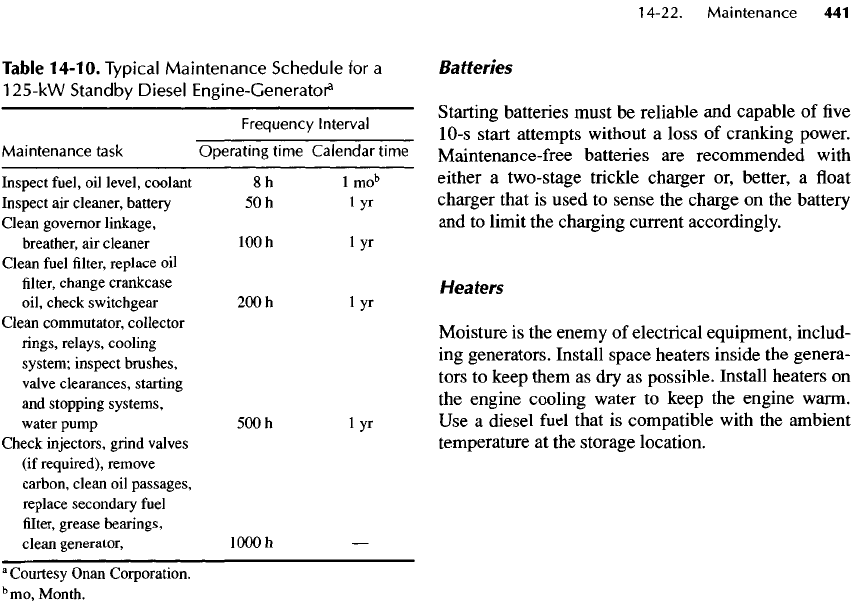
wear. Maintenance tasks
for
a
125-kW
diesel
engine-generator
set are
shown
in
Table
14-10.
On a
yearly contract,
the
total cost
of
maintenance labor
and
parts would
be
about
$700/yr
if
an
allowance
of 2 h
driving time
is
assumed
per
yearly
visit.
There
is a
considerable
difference between
the
maintenance
of
light, standby units
and
continuous-
duty
prime movers.
For
example,
the
service interval
for
valve overhaul
in a
heavy-duty engine
is 20
times
as
long
as the
interval given
for the
light-duty engine
in
Table
14-
10.
Exercising Engines
Instructions vary,
but the
following recommendations
are
good practice
for
modern engines.
Continuous-Duty
Engines
At
least once every
6
months,
all
engines should
be
operated
at the
rated load
for at
least
5 to 10 min
after
reaching operating temperatures
to
ensure that
the
engine
is
capable
of
developing
the
required rated
power.
Standby
Service
Every
6
months
to a
year,
all
engines should
be
full-
load tested
as
follows:
Operate
at 1 or 2 min at no
load,
5 min at 25%
load,
5 min at 50%
load,
5 min at
75%
load,
and 5 min at
rated load.
Engines should
be
no-load exercised
at
least once
each month.
The
engine should
be run
just long
enough
to
ascertain that
the
starting
and
control sys-
tems
are
operating properly
and
that proper
oil
pres-
sure
is
obtained. Excessive no-load operation causes
the
exhaust system
to
"slobber"
—
a
problem that
is
mostly cosmetic (messy). Slobber,
an
oily discharge
from
the
manifold stemming
from
fuel
that
is
partly
unburned,
is
especially noticeable
in
modern direct-
injected
diesel engines.
The
exercising
can be
done
by
an
automatic timing device installed
in the
trans-
fer
switch. These devices
are
usually
1-week
cycle
timers.
There
are
2-
week
cycle timers,
but
they
may
not
be
available
for
most switches. Many engineers
dislike automatic
exercisers,
because
(1) an
operator
should
be
listening
to an
engine while
it is
exercised,
(2)
the
maintenance crew
may
depend
too
much
on
automation
and
neglect
the
trouble-forestalling
inspection
of the
running engine,
and (3)
very
few
automated exercising systems
can
adequately exer-
cise
the
engine under load.
The
owner should
be
con-
sulted
about automatic versus manual control
of
exercising.
Manufacturers'
Recommendations
Although
the
above exercising instructions comprise
one
manufacturer's
recommendation
for
modern engines,
there
are
many other makes
and
models
and
many older
engines. Owners should
be
advised
to
follow
the
maker's
recommendation
for the
particular engine model
and the
particular circumstances
of
service.
Table
14-8.
Data
for
Diesel
and
Natural
Gas
Engines
3
'
6
Item
Diesel engine
Gas
engine
Size
of
engine,
hp
1150 1150
Engine output,
kW 820 820
Engine speed, rev/min
1800 1200
Total engine price,
$
158,000.00
268,000.00
Down
payment,
$
58,000.00
68,000.00
Loan interest rate,
%
10.00 10.00
Inflation
rate,
%
4.00 4.00
Months
payment
due
120
120
Taxes,
$
9,875.00
16,570.00
Insurance,
$
0.00 0.00
Operation, h/yr 8000
8000
Fuel
No. 2
diesel
Dry
natural
gas
Fuel
price
1.00
$/gal
0.35
ft
3
Fuel consumption
at
average load
59.06
gal/h
9500
ft
3
/h
Oil
10W30
SAE 30
Oil
consumption
at
average load
0.14
gal/h
0.05
gal/h
Oil
change interval
500.
h
1000.
h
Sump
size,
gal
81.1 111.7
Overhaul interval
Overhaul
1
(top end)
6530.
h
16,006.
h
Overhaul
2
(major)
13,061.
h
48,017.
h
Overhaul
3
80,002.
h
a
Courtesy
of
Caterpillar,
Inc.
b
Prices
effective
June
1997.
ENRCCI
=
5700.
Table
14-9.
Financial Summary
for
Twenty
Years
of
Operations^
Diesel
cost
Natural
gas
cost
Item
$
$7h
tf/kW-h
$
$7h
tf/kW-h
Selling price
158,000
0.99 0.12
268,000
1.68 0.20
Interest 58,581
0.37 0.04
117,162
0.73 0.09
Taxes
9,875
0.06 0.01
16,570
0.10 0.01
Insurance
(omitted)
— — — — — —
Fuel
9,450,000
59.06
7.20
5,320,000
33.25
4.05
Oil
288,500
1.80 0.22
151,400
0.95 0.12
Preventive
maintenance 241,500
1.51 0.18
153,900
0.96 0.12
Components
567,500
0.36 0.04
107,600
0.67 0.08
Overhauls
937,900
5.86 0.72
295,800
1.85
0.23
Total cost
11,202,000
70.01 8.54
6,430,000
40.19 4.90
With
inflation
16,584,000
103.65
12.64
9,393,000
58.71 7.16
a
Courtesy
of
Caterpillar,
Inc.
b
Prices
effective
June
1997.
ENRCCI
=
5700.
Table
14-10.
Typical
Maintenance
Schedule
for a
125-kW
Standby Diesel
Engine-Generator
3
Frequency
Interval
Maintenance
task Operating time Calendar time
Inspect
fuel,
oil
level, coolant
8 h 1
mo
b
Inspect
air
cleaner, battery
5Oh
1 yr
Clean governor linkage,
breather,
air
cleaner
100
h 1 yr
Clean
fuel
filter,
replace
oil
filter,
change
crankcase
oil, check switchgear
200 h 1 yr
Clean commutator, collector
rings, relays, cooling
system; inspect brushes,
valve
clearances, starting
and
stopping systems,
water
pump
500 h 1 yr
Check injectors, grind valves
(if
required), remove
carbon, clean
oil
passages,
replace secondary
fuel
filter,
grease bearings,
clean generator,
100Oh
—
a
Courtesy
Onan
Corporation.
b
mo,
Month.
Batteries
Starting
batteries must
be
reliable
and
capable
of five
10-s
start attempts without
a
loss
of
cranking power.
Maintenance-free
batteries
are
recommended with
either
a
two-stage trickle charger
or,
better,
a float
charger that
is
used
to
sense
the
charge
on the
battery
and
to
limit
the
charging current accordingly.
Heaters
Moisture
is the
enemy
of
electrical equipment, includ-
ing
generators. Install space heaters inside
the
genera-
tors
to
keep them
as dry as
possible. Install heaters
on
the
engine cooling water
to
keep
the
engine warm.
Use a
diesel
fuel
that
is
compatible
with
the
ambient
temperature
at the
storage location.
In
this chapter,
the
uses
of
variable-speed (V/S) pump
operation
in
water
and
wastewater pumping stations
are
presented
and
discussed.
The
principal adjustable-
and
variable-speed drives
are
reviewed
and
compared.
The
primary goal
of V/S
wastewater pumping
is to
keep
the
station discharge rate equal
to the
influent
rate
at
all
times.
The
station acts
as
though
it
were
a
sewer
discharging
by
gravity.
A
pumping station that meets
this
goal requires very little
(if
any) storage
in the wet
well,
does
not
rapidly cycle
any of the
pumps,
and
does
not
cause abrupt, large changes
in the
discharge rate.
The
primary goal
of V/S
booster pumping
is to
maintain
a
nearly constant pressure
at all
times
regardless
of the
demand.
The
discussion given here
for
V/S
booster pumping also applies
to
high-
service
(high
head) pumping
for
reducing water hammer
in
very
long transmission mains. Otherwise,
V/S is
rarely
used
for
water pumping.
Chapter
1
5
Variable-Speed Pumping
MAYO
GOTTLIEBSON
ROBERT
L.
SANKS
CONTRIBUTORS
Stefan
M.
Abel
in
Roberts.
Benfell
Harrison
C.
Bicknell
Ronald
W.
Duncan
Stanley
S.
Hong
Casey Jones
Paul
C.
Leach
Timothy
Nance
Michael
R.
Olson
E.
O.
Potthoff
Arnold
R.
Sdano
Richard
N.
Skeehan
Earle
C.
Smith
Patricia
A.
Trager
In
common usage,
the
term
"variable
speed"
indi-
cates that
the
speed
of the
pump
is
regulated
to
pro-
duce
the
desired discharge.
Electrical
engineers,
however,
consider "variable
speed"
to
mean that
the
motor speed varies with
the
load, while
the
term
"adjustable
speed"
means that
the
speed
is
nearly
independent
of
load.
An
example
of an
adjustable-
speed drive
is an
adjustable-frequency drive (AFD),
sometimes mistakenly called
a
"variable-frequency"
drive.
An
example
of a
variable-speed drive
is a
liquid
rheostat
in
which, although speed varies with both
load
and
control,
the
proper speed
can be
attained
by
the
external control. Thus, pump speed
can be
varied
at
will
by
either
an
adjustable-
or a
variable-speed
drive.
In
this chapter, both kinds
of
drives
are
called
"variable
speed"
or
"V/S"
for
convenience,
but
when
communicating
with electrical engineers,
confusion
can
be
avoided
by
strict usage
of
correct terminology.
Applications
to
both water
and
wastewater pump-
ing
are
described
in
Sections 15-1, 15-3,
and
15-11.
Sections
15-2
and
15-4 through 15-6
are
generally
devoted
to
wastewater pumping,
and
Sections 15-7
through
15-10
are
confined
to
water booster pumping.
15-1.
Variable
Speed versus Constant Speed
The
difference
between
V/S and
constant-
speed
(C/S)
pumping
is
profound
and has
far-reaching conse-
quences,
so the
choice should
not be
lightly made.
Some reasons
for the
choice
of V/S or C/S for a
partic-
ular
pumping station
may be
compelling while
others,
which
may be
significant
for a
different
situation,
may
be
trivial. Nevertheless,
all of the
reasons should
be
considered thoughtfully.
Advantages
of
Variable-Speed
Pumping
The
major
advantages
of V/S
pumping, stemming
from
the
objective that discharge always equals
influ-
ent
flowrate,
are:
• No
storage
is
required,
so the wet
well
can be
smaller, shallower,
and
less expensive than
for C/S
pumping,
and
size might compensate
for the
high
cost
of the V/S
equipment.
•
Fewer
—
although
larger
—
pumps
are
needed
in
medium-
to
large-sized stations with savings
in
space
for the
pump room
and
less equipment
to
maintain.
•
Downstream
flowrates fluctuate
slowly
and do not
upset
treatment processes caused
by
surges
nor do
the
sudden surges caused
by C/S
pumping pound
downstream
piping.
• The
almost constant
wet
well surface
and
short
resi-
dence time tend
to
reduce
the
production
of
odors
and
corrosive gasses.
•
Energy savings
are
likely
due to the
higher average
wet
well surface elevation
and the
usually lower
pumping
rates
and
lower pipe
friction
losses.
• If
adequate cooling
is
provided, motor
life
is
pro-
longed because
of the
infrequent
starts.
• The
high inrush current that characterizes across-
the-line
starts
of C/S
drivers
is
greatly reduced
in
adjustable-frequency
drives (AFDs)
and
liquid
rheostats (although
not in
eddy-current couplings).
• The
soft
and
reduced number
of
starts
do not
cause
annoying
power dips
in
nearby buildings. Power
dips caused
by
across-the-line
starts
for C/S
pumps
can be
avoided with
soft
start equipment,
but the
cost
of
such equipment makes adjustable-frequency
drives
more attractive economically.
Throttling
the
engine
of a
direct engine drive
is a
simple, inexpensive,
and
reliable means
of
achieving
V/S,
but
read Sections 14-2
and
14-22
and
consult
the
engine manufacturers regarding
the
problems
of
oper-
ating
diesel
or gas
engines
at
less than
full
load.
Wastewater
The
reasons
for
using
V/S
pumping
for
wastewater
include
the
following:
•
Continuous pumping
and the
very short liquid resi-
dence time
in V/S
operation eliminates
or
reduces
(1) the
deposition
of
organic
solids
—
a
problem
in
C/S
pumping because
of the
difficulty
of
resuspen-
sion;
(2)
putrefaction
—
so
the
sewage
is
easier
and
less costly
to
treat;
(3) the
production
of
odors
and
corrosive, poisonous gases;
and (4)
cyclic rise
and
fall
of
the
water
surface
with
the
resulting pumping
of
sewer gases into
the
atmosphere.
• V/S
pumping eliminates
the
long,
free
fall
of
sew-
age and the
entrainment
of air
bubbles that,
if
sucked into
the
pump, greatly reduce pump
effi-
ciency, although this advantage disappears
in a
comparison with
C/S
pumping
if a
sloping
approach
pipe
is
used (see Section 12-7).
• The
average static head
in C/S
pumping
can be
reduced
by 0.6 m (2 ft) or
more
in V/S
pumping
by
keeping
the wet
well level
the
same
as the
normal
level
in the
influent
sewer (see Section 12-6
and
Figure 12-35). Turbulence
is
thereby virtually elim-
inated,
and the
release
of
odorous gases
is
substan-
tially reduced.
The
energy cost savings
due to the
consistently high
wet
well level
may be
significant.
• One
important reason
for
using
V/S
pumping
is to
produce gradual changes
in flow
that
do not
upset
(and
thereby reduce
the
efficiency
of)
downstream
processes
such
as
sedimentation. Sudden
flow
changes caused
by C/S
pumps, even
at
significant
distances
from
a
treatment plant,
can
upset
the
entire treatment
process.
At one
utility,
it was
found
that
such
flow
changes propagated through
the
entire primary/secondary treatment
process
and
were upsetting
the
dechlorination
system. Forcing
the
operators
to use the V/S
drives (that
had
been
installed but,
due to
indifference,
not
used) solved
the
problem.
Water
Water
is
customarily pumped
for
long periods
(of
sev-
eral hours)
at
uniform rates
(often
to fill
reservoirs
or
tanks),
so
there
are
fewer
reasons
for
choosing
V/S
for
pumping water than
for
pumping wastewater,
although
they
may be
just
as
compelling.
