Pumping Station Desing - Second Edition by Robert L. Sanks, George Tchobahoglous, Garr M. Jones
Подождите немного. Документ загружается.

flowmeter
can
be any
type that
has a 4- to
20-mA
out-
put
signal. Accuracy
is not
usually important. Because
the
valve should modulate
in
response
to the
flowme-
ter
output
signal,
a
hydraulically operated valve
is
usually
preferred.
The
valve actuator
is
adjusted
to
maintain
the
rec-
ommended
minimum pump discharge rate (RMPDR)
through
the
valve when
the
demand
is
zero.
The
valve
should
be
fully
closed when
the
demand exceeds
the
RMPDR
by 25 to
35%.
At
demands less than
the
RMPDR,
the
valve modulates
to
maintain
the flow
through
the flowmeter
equal
to or
slightly greater than
the
RMPDR.
If
two
pumps
are to
operate
in
parallel,
as
shown
in
Figure
15-2Ob,
the
signal
from
the flowmeter
should
be
electronically converted
to
cause
the
valve
to
main-
tain
a
minimum combined discharge rate
of
twice
the
RMPDR
when both pumps
are
operating. This
method
of
operation, however, applies only
to
load-
sharing parallel operation,
as
explained below.
A
bypass around
the flowmeter
(not shown
in
Fig-
ure
15-20)
is
desirable
so
that
the
meter
can be
removed
for
repairs (see Figure
20-12).
The
modulating
or
regulating valves shown
in
Fig-
ure
15-20 would nearly always operate
as
throttling
valves
subject
to
cavitation.
The
valve selected must
be
capable
of
withstanding such severe service
for
many
years.
It
should
be of the
type
in
which metering
occurs
downstream
from
the
seat,
and the
cavitation
constant
should
be
greater than
1.0.
If
metering occurs
in
the
seat
(as in an
ordinary globe valve),
the
seat will
be
quickly cut.
If the
pressure drop
is
excessive
for a
single
valve,
two
valves
can be
installed
in
series.
Jockey Pump
Include
a
relatively small,
flat-curve,
constant-
speed
jockey pump
to
operate during periods
of low
demand.
The V/S
pumps
do not
operate while
the
jockey pump
is
running. Because
the
head
in the
pump suction
header
is
high when
the flowrate is
low,
the
jockey
pump
can be
selected
for a
relatively
low
head.
The
jockey pump
is
usually started
and
stopped
by
means
of
pressure switches with suitable time delays
to
prevent starting
and
stopping
on
pressure surges.
The
switches sense pressure
in the
station suction
header.
If the
suction pressure variation
at low flows is
too
little
for
reliable pressure switch operation,
it may
be
necessary
to use a flow-measuring
device
to
start
and
stop
the
jockey pump.
Hydropneumatic
Tank
A
small hydropneumatic tank with
an air
compressor
and
an
appropriate air/water ratio controller
can be
used
with
C/S
pumps.
It is
rarely used with
V/S
pumps.
15-9.
Operations
in
Booster
Pumping
Booster pumps
can be
operated
in
parallel
in
much
the
same
way as
described
in
Section 15-4, except that
the
difference
in
power requirement
is
even greater. Typi-
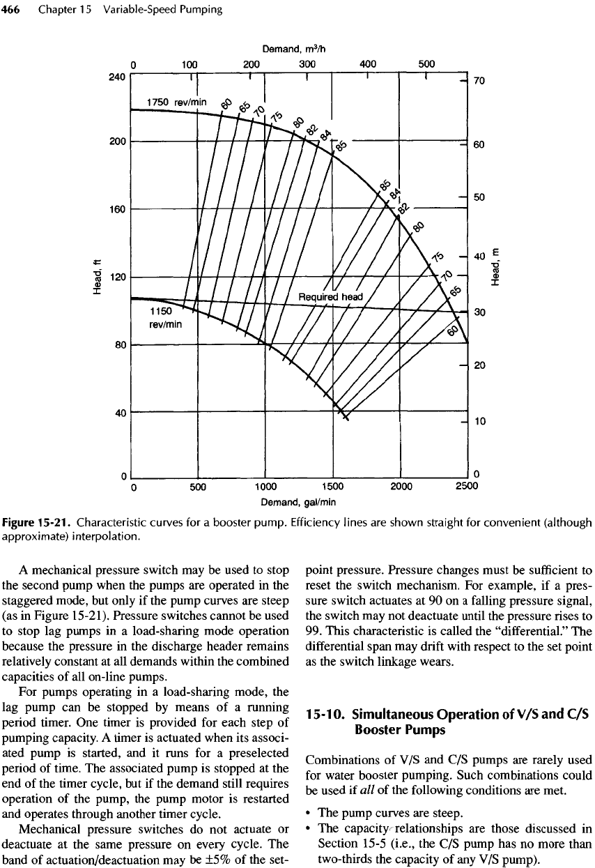
cal, steep characteristic curves
of a
booster pump
are
shown
in
Figure 15-21 with
the
required head curve
superimposed. When
two of
these pumps
are
operated
in
parallel,
the
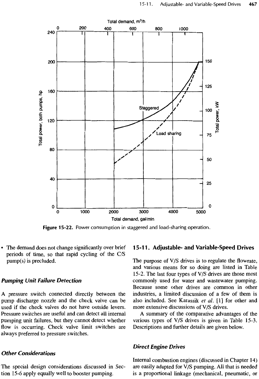
total power required
in
both types
of
operation
is as
shown
in
Figure 15-22.
With
a
different
combination
of
pump and/or
required head curves,
the
difference
in
power require-
ments
may be
more
or
less pronounced than
in
this
example,
but a
situation
in
which staggered operation
would
use
only
a
little more power than load sharing
throughout
a
significant portion
of the
discharge
would
be
most unusual.
Sequencing
Starting
Lag
Pumps
A
high-quality, mechanical pressure switch that
senses pressure
in the
discharge header could
be
used
to
signal
the
second pump
to
start
but
only
if the
pump
curve
is
steep.
For
starting either
(1) flat-curve
second
pumps
or (2)
third (and subsequent)
flat- or
steep-
curve
pumps,
the
recommended method
is to use
sig-
nals
from
a flowmeter and a
pressure switch.
The lag
pumps
are
normally started either
(1)
when
the
header
flowrate
approaches
the
maximum discharge rate
of
the
on-line pumps
or (2)
when
the
pressure
in the
dis-
charge header
is
low. Time delays should
be
included
in
pressure switch circuits
to
prevent action
on
momentary
pressure
fluctuations.
Pressure switches alone should
not be
used
to
pro-
vide starting signals
for flat-curve
pumps
or
pumps
subsequent
to the
second pump, because
the
pumps
on
line
may
cavitate before
the
pressure
in the
discharge
header
falls
enough (about
10%
below
the
desired
head)
to
actuate
the
pressure switch.
Stopping
Lag
Pumps
The
preferred method
of
stopping
lag
pumps
is
always
by
means
of
signals
from
a flowmeter
plus
an
elec-
tronic pressure switch. Each
lag
pump
is
stopped when
(1)
the
demand falls
to
within
the
combined capacities
of
the
remaining on-line pumps
and (2) the
pressure
in
the
discharge header
is at the
desired value.
A
mechanical pressure switch
may be
used
to
stop
the
second pump when
the
pumps
are
operated
in the
staggered mode,
but
only
if the
pump curves
are
steep
(as
in
Figure 15-21). Pressure switches cannot
be
used
to
stop
lag
pumps
in a
load-sharing mode operation
because
the
pressure
in the
discharge header remains
relatively
constant
at all
demands within
the
combined
capacities
of all
on-line pumps.
For
pumps operating
in a
load-sharing mode,
the
lag
pump
can be
stopped
by
means
of a
running
period
timer.
One
timer
is
provided
for
each step
of
pumping
capacity.
A
timer
is
actuated when
its
associ-
ated pump
is
started,
and it
runs
for a
preselected
period
of
time.
The
associated pump
is
stopped
at the
end of the
timer cycle,
but if the
demand still requires
operation
of the
pump,
the
pump motor
is
restarted
and
operates through another timer cycle.
Mechanical pressure switches
do not
actuate
or
deactuate
at the
same pressure
on
every
cycle.
The
band
of
actuation/deactuation
may be ±5% of the
set-
point pressure. Pressure changes must
be
sufficient
to
reset
the
switch mechanism.
For
example,
if a
pres-
sure
switch actuates
at 90 on a
falling
pressure signal,
the
switch
may not
deactuate until
the
pressure rises
to
99.
This characteristic
is
called
the
"differential."
The
differential
span
may
drift
with respect
to the set
point
as
the
switch linkage wears.
1
5-1
0.
Simultaneous
Operation
of V/S and C/S
Booster
Pumps
Combinations
of V/S and C/S
pumps
are
rarely used
for
water booster pumping. Such combinations could
be
used
if all of the
following conditions
are
met.
• The
pump curves
are
steep.
• The
capacity relationships
are
those discussed
in
Section
15-5
(i.e.,
the C/S
pump
has no
more than
two-thirds
the
capacity
of any V/S
pump).
Figure
15-21.
Characteristic curves
for a
booster
pump.
Efficiency lines
are
shown straight
for
convenient
(although
approximate)
interpolation.
• The
demand does
not
change
significantly
over brief
periods
of
time,
so
that rapid cycling
of the C/S
pump(s)
is
precluded.
Pumping
Unit
Failure
Detection
A
pressure switch connected directly between
the
pump
discharge nozzle
and the
check valve
can be
used
if the
check valves
do not
have outside levers.
Pressure switches
are
useful
and can
detect
all
internal
pumping
unit failures,
but
they cannot detect whether
flow
is
occurring. Check valve limit switches
are
always
preferred
to
pressure switches.
Other
Considerations
The
special
design considerations discussed
in
Sec-
tion
15-6
apply equally well
to
booster pumping.
15-11.
Adjustable-
and
Variable-Speed
Drives
The
purpose
of V/S
drives
is to
regulate
the flowrate,
and
various means
for so
doing
are
listed
in
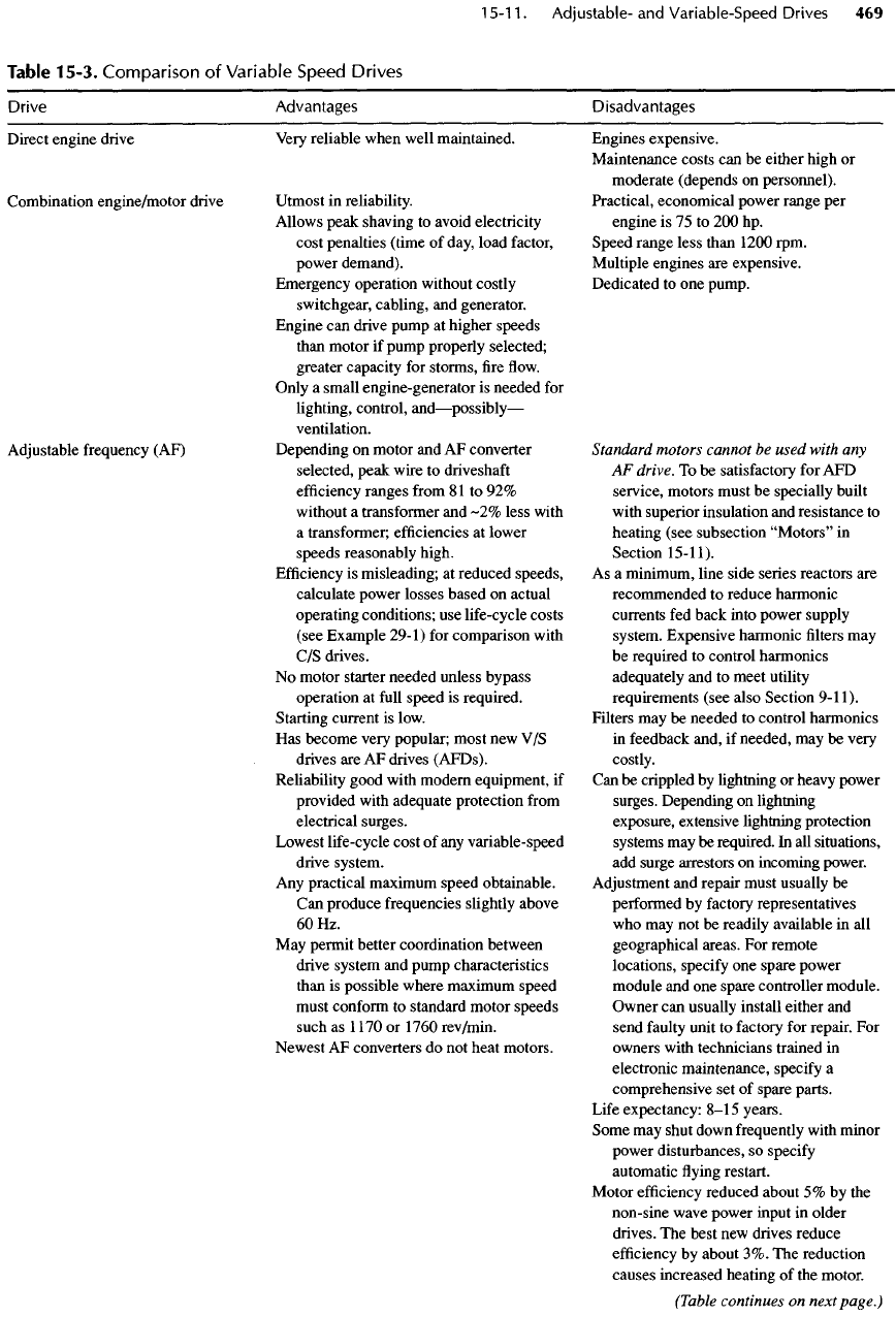
Table
15-2.
The
last
four
types
of V/S
drives
are
those most
commonly
used
for
water
and
wastewater pumping.
Because some other drives
are
common
in
other
industries,
a
limited discussion
of a few of
them
is
also included.
See
Karassik
et
al
[1] for
other
and
more extensive discussions
of V/S
drives.
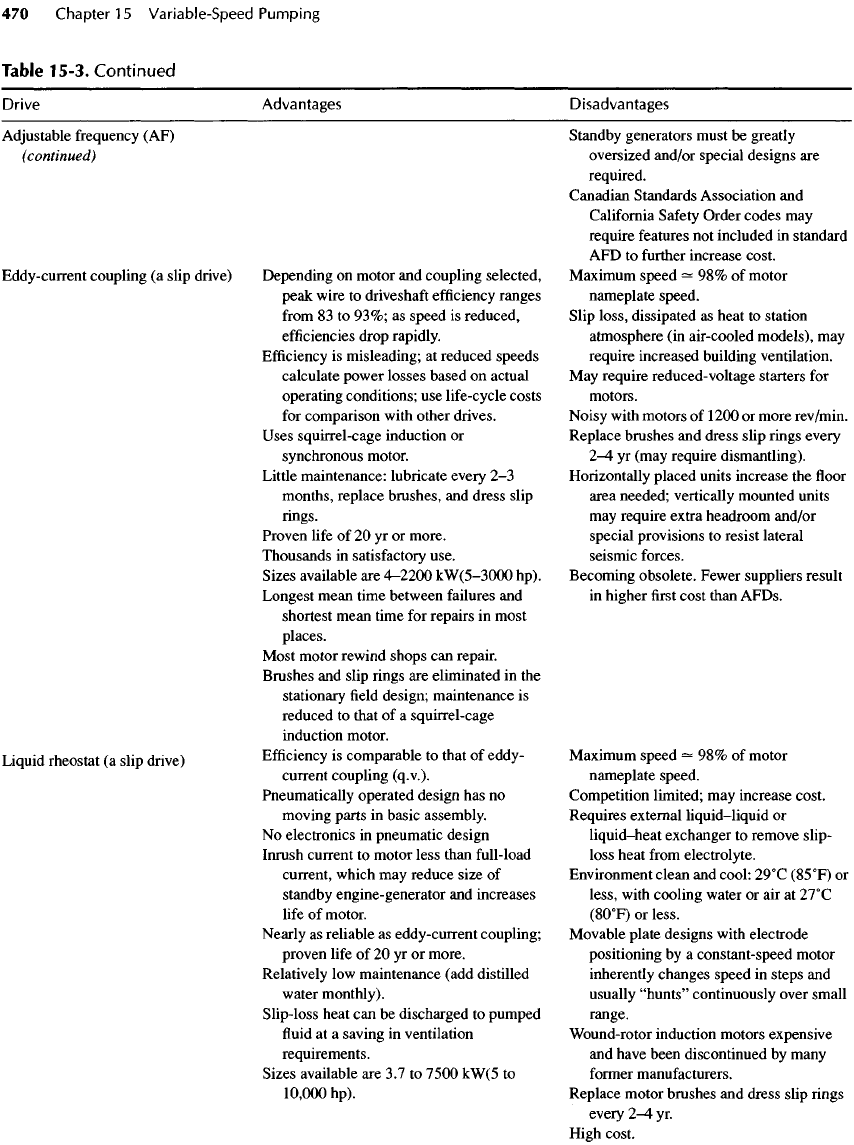
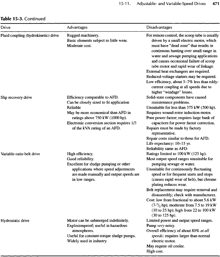
A
summary
of the
comparative advantages
of the
various
types
of V/S
drives
is
given
in
Table 15-3.
Descriptions
and
further
details
are
given below.
Direct
Engine
Drives
Internal combustion engines (discussed
in
Chapter
14)
are
easily adapted
for V/S
pumping.
All
that
is
needed
is
a
proportional linkage (mechanical, pneumatic,
or
Figure
15-22.
Power
consumption
in
staggered
and
load-sharing
operation.
electrical) between
the
sump level
or a
header pres-
sure
monitor
and the
governor. Note that prolonged
operation
at low
loads causes carbon deposits
in a
die-
sel
engine exhaust system (see Section 14-22).
Right-angle
gears
can be
used
to
adapt
the
horizon-
tally
mounted engine
to a
vertical pump
shaft.
Nonre-
versing
gears should
be
used.
The
connection between
the
driveshaft
and a
horizontal pump
shaft
should
be
flexible
to
limit vibration transfer.
Engine drives
are
ideally suited
for the
following:
•
Pumping stations that, because
of
size
or
location,
are a
problem
for
electrical facilities.
It may be
more economical
to use
engines than
to
install long,
large transmission power lines.
• In
some water hammer situations where
the
required inertia
of
moving parts
is
greater than eco-
nomically
feasible
for
electric motor drives.
•
Locations where gaseous
fuels
are
available
at low
cost
—
near
natural
gas
centers
or
large sewage treat-
ment
plants with surplus digester gas.
Engine-Generator Drives
If
power must
be
locally generated
by an
engine,
V/S
pumping
can be had for
almost
no
added expense
by
controlling
the
generator speed with
an
asynchronous
engine governor that responds
to
changes
in the
con-
trolled variable (such
as
sump level
or
discharge pres-
sure)
to
produce
a
variable-frequency power source.
One or
more pump motors
can be
powered
by one
generator
in
load-sharing operation. With
a
back-up
engine-generator
set
(which
is
usually required any-
way),
this system
is
very reliable.
Combination Drives
If
the
utmost
in
reliability
is
required
of the
standby
power system, consider using direct-drive standby
engines
for
duty
and
standby pumps instead
of an
engine-generator set.
For
horizontal split-case pumps,
the
motor
is
mounted
at one end of the
pump
shaft
and
the
engine
is
mounted through
an
automatic
clutch
at the
other end.
If a
vertical motor drives
the
pump,
a
combination right-angle gear
and
automatic
clutch
is
available
to
provide
a
horizontal
shaft
for an
engine
and a
mount
for a
vertical motor.
If
power fails,
the
duty engine
is
started
and the
motor
is
allowed
to
spin
freely.
An
interlock must dis-
connect
the
motor
from
the
power source when
the
engine
is
started. When electric power
is
restored,
the
pump
must
first
slow
to
well below synchronous
speed
and the
engine must
be
disconnected before
the
motor
is
energized. Energizing
a
spinning motor
Table
15-2. Systems
for
Regulating
Flowrate
or
Pressure
Motive
unit speed Pump speed Regulating
system
Notes
and
examples
Constant
Constant
Throttling
valve Pump
may run
near
zero
discharge;
for
water
pumping
only
Constant
Constant
Regulating
valve
Excess
pump
discharge
spilled
to
sump
intake;
for
water
pumping
only
Constant
Constant
Variable-pitch
propeller
Propeller
pumps
for
pumping
very
large
storm
water
flows
Constant
Constant
Intermittent
operation
Storage
in wet
well
or
clear
well;
and
usually
multiple
variable
number
of
duty
pumps
in
parallel
pumps
Constant Variable
Mechanical
drive
Oil film
cone
rollers,
automatic
gears,
vee
belt
Constant
Variable Hydraulic
coupling
Hydrokinetic,
hydroviscous
Constant
Variable
Hydrostatic
drive
Hydraulic
pump
and
hydraulic
motor
with
squirrel-cage
motor
Variable Variable
Slip
energy
recovery
Wound-rotor
motor
Variable Variable
Engine
drive
Throttle
fuel
Adjustable Variable
Electronic
Adjustable-frequency drive
Variable Variable
Slip
drive Liquid
rheostat
with wound-rotor
motor
Constant
Variable
Slip
drive
Eddy-current
coupling
Drive
Direct engine drive
Combination
engine/motor drive
Adjustable
frequency
(AF)
Advantages
Very
reliable when well maintained.
Utmost
in
reliability.
Allows
peak shaving
to
avoid electricity
cost penalties (time
of
day, load factor,
power demand).
Emergency operation without costly
switchgear,
cabling,
and
generator.
Engine
can
drive pump
at
higher speeds
than
motor
if
pump properly selected;
greater capacity
for
storms,
fire flow.
Only
a
small engine-generator
is
needed
for
lighting,
control,
and
—
possibly
—
ventilation.
Depending
on
motor
and AF
converter
selected, peak wire
to
driveshaft
efficiency
ranges
from
81
to 92%
without
a
transformer
and
~2%
less
with
a
transformer;
efficiencies
at
lower
speeds reasonably high.
Efficiency
is
misleading;
at
reduced speeds,
calculate power
losses
based
on
actual
operating conditions;
use
life-cycle costs
(see Example
29-1)
for
comparison with
C/S
drives.
No
motor starter needed unless bypass
operation
at
full
speed
is
required.
Starting current
is
low.
Has
become very popular; most
new V/S
drives
are AF
drives (AFDs).
Reliability good with modern equipment,
if
provided with adequate protection
from
electrical surges.
Lowest
life-cycle cost
of any
variable-speed
drive system.
Any
practical maximum speed obtainable.
Can
produce frequencies slightly above
60Hz.
May
permit better coordination between
drive system
and
pump characteristics
than
is
possible where maximum speed
must
conform
to
standard motor speeds
such
as
1
170
or
1760 rev/min.
Newest
AF
converters
do not
heat motors.
Disadvantages
Engines expensive.
Maintenance costs
can be
either high
or
moderate (depends
on
personnel).
Practical, economical power range
per
engine
is 75 to 200 hp.
Speed
range less than 1200
rpm.
Multiple
engines
are
expensive.
Dedicated
to one
pump.
Standard
motors cannot
be
used
with
any
AF
drive.
To be
satisfactory
for AFD
service, motors must
be
specially built
with
superior insulation
and
resistance
to
heating (see subsection
"Motors"
in
Section
15-11).
As
a
minimum, line side
series
reactors
are
recommended
to
reduce harmonic
currents
fed
back into power supply
system. Expensive harmonic
filters may
be
required
to
control harmonics
adequately
and to
meet utility
requirements (see also Section
9-11).
Filters
may be
needed
to
control harmonics
in
feedback and,
if
needed,
may be
very
costly.
Can
be
crippled
by
lightning
or
heavy power
surges. Depending
on
lightning
exposure, extensive lightning protection
systems
may be
required.
In all
situations,
add
surge
arrestors
on
incoming power.
Adjustment
and
repair must usually
be
performed
by
factory representatives
who
may not be
readily available
in all
geographical areas.
For
remote
locations, specify
one
spare power
module
and one
spare controller module.
Owner
can
usually install
either
and
send
faulty
unit
to
factory
for
repair.
For
owners
with technicians trained
in
electronic maintenance, specify
a
comprehensive
set of
spare parts.
Life
expectancy:
8—15
years.
Some
may
shut down frequently with minor
power disturbances,
so
specify
automatic
flying
restart.
Motor
efficiency
reduced about
5% by the
non-sine wave power input
in
older
drives.
The
best
new
drives reduce
efficiency
by
about
3%. The
reduction
causes
increased
heating
of the
motor.
Table 15-3.
Comparison
of
Variable
Speed
Drives
Table
15-3.
Continued
Drive
Adjustable
frequency
(AF)
(continued)
Eddy-current
coupling
(a
slip drive)
Liquid
rheostat
(a
slip drive)
Advantages
Depending
on
motor
and
coupling selected,
peak wire
to
driveshaft
efficiency
ranges
from
83 to
93%;
as
speed
is
reduced,
efficiencies
drop rapidly.
Efficiency
is
misleading;
at
reduced
speeds
calculate power losses based
on
actual
operating conditions;
use
life-cycle costs
for
comparison with other drives.
Uses squirrel-cage induction
or
synchronous
motor.
Little
maintenance: lubricate every
2-3
months, replace brushes,
and
dress slip
rings.
Proven
life
of 20 yr or
more.
Thousands
in
satisfactory use.
Sizes available
are
4-2200
kW(5-3000
hp).
Longest mean time between failures
and
shortest mean time
for
repairs
in
most
places.
Most motor rewind shops
can
repair.
Brushes
and
slip rings
are
eliminated
in the
stationary
field
design; maintenance
is
reduced
to
that
of a
squirrel-cage
induction motor.
Efficiency
is
comparable
to
that
of
eddy-
current
coupling (q.v.).
Pneumatically
operated design
has no
moving
parts
in
basic assembly.
No
electronics
in
pneumatic design
Inrush
current
to
motor less than
full-load
current,
which
may
reduce
size
of
standby
engine-generator
and
increases
life
of
motor.
Nearly
as
reliable
as
eddy-current coupling;
proven
life
of 20 yr or
more.
Relatively
low
maintenance (add distilled
water
monthly).
Slip-loss heat
can be
discharged
to
pumped
fluid
at
a
saving
in
ventilation
requirements.
Sizes available
are 3.7 to
7500
kW(5
to
10,000
hp).
Disadvantages
Standby
generators must
be
greatly
oversized and/or special designs
are
required.
Canadian Standards Association
and
California
Safety
Order codes
may
require
features
not
included
in
standard
AFD
to
further
increase
cost.
Maximum
speed
— 98% of
motor
nameplate speed.
Slip loss, dissipated
as
heat
to
station
atmosphere
(in
air-cooled
models),
may
require
increased
building ventilation.
May
require
reduced-
voltage
starters
for
motors.
Noisy
with motors
of
1200
or
more rev/min.
Replace brushes
and
dress slip rings every
2-4
yr
(may require dismantling).
Horizontally placed units increase
the floor
area needed; vertically mounted units
may
require extra headroom and/or
special provisions
to
resist lateral
seismic forces.
Becoming obsolete. Fewer suppliers result
in
higher
first
cost than AFDs.
Maximum
speed
— 98% of
motor
nameplate speed.
Competition limited;
may
increase cost.
Requires external
liquid-liquid
or
liquid—
heat
exchanger
to
remove slip-
loss heat
from
electrolyte.
Environment clean
and
cool:
29
0
C
(85
0
F)
or
less, with cooling water
or air at
27
0
C
(8O
0
F)
or
less.
Movable plate designs with electrode
positioning
by a
constant-speed motor
inherently changes speed
in
steps
and
usually
"hunts"
continuously over small
range.
Wound-rotor
induction motors expensive
and
have been discontinued
by
many
former
manufacturers.
Replace motor brushes
and
dress slip rings
every
2-4
yr.
High cost.
Table
15-3.
Continued
Drive
Fluid coupling (hydrokinetic) drive
Slip
recovery drive
Variable-ratio belt drive
Hydrostatic
drive
Advantages
Rugged machinery.
Basic elements subject
to
little wear.
Moderate cost.
Efficiency
comparable
to
AFD.
Can
be
closely sized
to fit
application
Reliable
May
be
more economical than
AFD in
ratings above
750 kW
(1000 hp).
Electronic conversion section requires
1/3
of
the kVA
rating
of an
AFD.
High
efficiency.
Good reliability.
Excellent
for
sludge pumping
or
other
applications where speed adjustments
are
made manually
and
output
speeds
are
in
low
ranges.
Motor
can be
submerged indefinitely.
Explosionproof
;
useful
in
hazardous
atmospheres.
Useful
for
constant-torque sludge pumps.
Widely
used
in
industry.
Disadvantages
For
remote control,
the
scoop tube
is
usually
driven
by a
small
electric
motor, which
must
have
"dead
zone"
that results
in
continuous hunting over small range
in
water
and
sewage pumping
applications
and
causes occasional failure
of
scoop
tube
motor
and
rapid wear
of
linkage.
External heat exchangers
are
required.
Reduced-voltage starters
may be
required.
Low
efficiency,
about 5-7%
less
than eddy-
current
coupling
at all
speeds
due to
higher
"windage"
losses.
Solid-state components have caused
maintenance problems.
Unsuitable
for
less than
375 kW
(500 hp).
Requires wound-rotor induction motor.
Poor power factor; requires large bank
of
capacitors
for
power
factor
correction.
Repairs must
be
made
by
factory
representative.
Repair costs similar
to
those
for
AFD.
Life
expectancy:
10—
15
yr.
Reliability
same
as
AFD.
Ratings
limited
to 100 kW
(125 hp).
Most
output speed ranges unsuitable
for
pumping
sewage
or
water.
Unsuitable
for
continuously
fluctuating
speed
or for
frequent
starts
and
stops
(causes rapid wear
of
belt),
but
chrome
plating
reduces wear.
Belt replacement
may
require removal
and
disassembly; check with manufacturer.
Cost:
low
from
fractional
to
about
5.6 kW
(7-V
2
hp); moderate
from
7.5 to 19 kW
(10 to 25
hp); high
from
22 to 100 kW
(30 to 125
hp).
Limited power
and
output speed ranges.
Pump
very
noisy.
Overall
efficiency
of
about
80% at all
speeds;
requires larger than normal
electric motor.
May
require
oil
cooler.
High
cost.
might
not
harm
it
(unless
it is
spinning
in
reverse),
but
energizing
a
spinning motor with
its
residual
field
remaining
from
interrupted
electrical
power
by
con-
necting
it to
another, non-synchronized power source
could
displace
the
windings, break
the
shaft,
and
probably shear coupling bolts.
Peak
Shaving
Significant
savings
in
power costs
can
sometimes
be
obtained
by
using
the
motor
to
drive
the
pump
for low
and
medium
flows and by
switching
to
engine drive
for
high
flows. The
advantages include
• A
smaller electric motor
• Two or
three
small-
to
medium-sized
engines
and
drive
gears (plus
a
very small engine-generator
set
for
controls
and
lighting) replace
a
large engine-
generator
set and
expensive electrical transfer
switch
• A
lower
electric
power demand
• The
engine need
not be
"exercised"
if
high
flows
occur with
sufficient
frequency
• The
engine always operates
at or
near
full
load.
The
design
of a
peak shaving system requires
an
extensive study
of
diurnal
and
monthly
flowrates. A
convenient
and
simple
aid is the use of
either arith-
metic
or log
probability paper
[2].
Fair
et
al
[3]
have
explained
the use of
probability paper.
Adjustable-Frequency
Drives
The
adjustable-frequency drive (AFD) consists
of an
adjustable
frequency
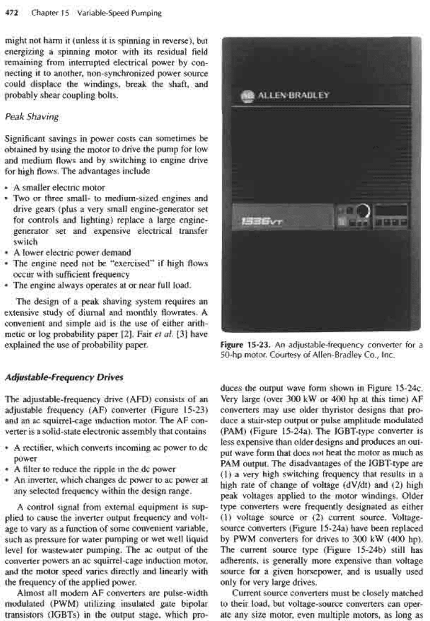
(AF) converter (Figure 15-23)
and
an ac
squirrel-cage
induction motor.
The AF
con-
verter
is a
solid-state electronic assembly that contains
• A
rectifier, which converts incoming
ac
power
to dc
power
• A filter to
reduce
the
ripple
in the dc
power
• An
inverter, which changes
dc
power
to ac
power
at
any
selected
frequency within
the
design range.
A
control signal
from
external equipment
is
sup-
plied
to
cause
the
inverter output
frequency
and
volt-
age to
vary
as a
function
of
some convenient variable,
such
as
pressure
for
water pumping
or wet
well liquid
level
for
waste
water
pumping.
The ac
output
of the
converter powers
an ac
squirrel-cage induction motor,
and
the
motor speed varies directly
and
linearly with
the
frequency
of the
applied power.
Almost
all
modern
AF
converters
are
pulse-width
modulated (PWM) utilizing insulated gate bipolar
transistors (IGBTs)
in the
output stage, which pro-
Figure
15-23.
An
adjustable-frequency
converter
for a
50-hp
motor.
Courtesy
of
Allen-Bradley
Co.,
Inc.
duces
the
output wave
form
shown
in
Figure
15-24c.
Very
large (over
300 kW or 400 hp at
this time)
AF
converters
may use
older thyristor designs that pro-
duce
a
stair-step output
or
pulse amplitude modulated
(PAM)
(Figure 15-24a).
The
IGBT-type
converter
is
less expensive than older designs
and
produces
an
out-
put
wave
form
that does
not
heat
the
motor
as
much
as
PAM
output.
The
disadvantages
of the
IGBT-type
are
(1)
a
very high switching frequency that results
in a
high
rate
of
change
of
voltage (dV/dt)
and (2)
high
peak voltages applied
to the
motor windings. Older
type
converters were
frequently
designated
as
either
(1)
voltage source
or (2)
current source. Voltage-
source converters (Figure
15-24a)
have
been
replaced
by
PWM
converters
for
drives
to 300 kW
(400 hp).
The
current source type (Figure
15-24b)
still
has
adherents,
is
generally more expensive than voltage
source
for a
given horsepower,
and is
usually used
only
for
very large drives.
Current
source
converters must
be
closely
matched
to
their load,
but
voltage-source converters
can
oper-
ate any
size motor, even multiple motors,
as
long
as
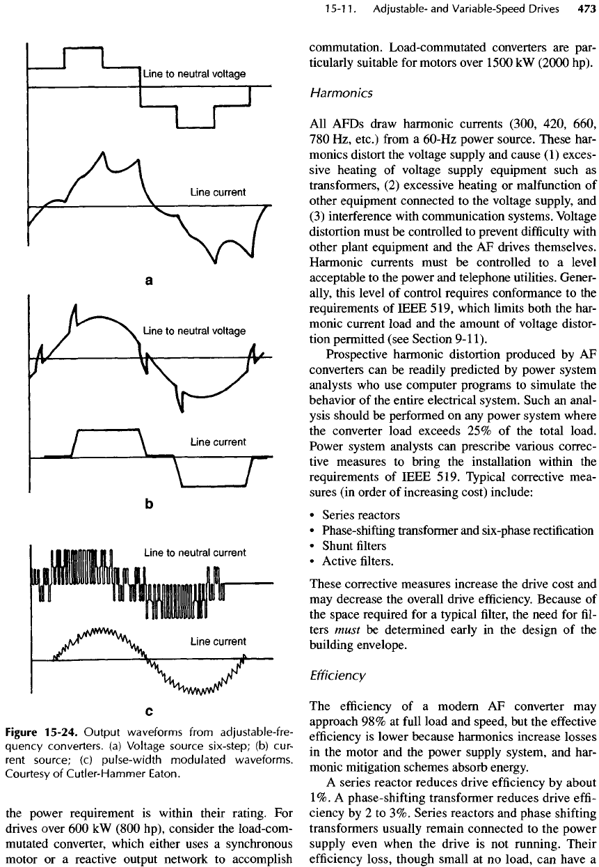
Figure
15-24.
Output waveforms
from
adjustable-fre-
quency
converters,
(a)
Voltage
source
six-step;
(b)
cur-
rent
source;
(c)
pulse-width
modulated waveforms.
Courtesy
of
Cutler-Hammer
Eaton.
the
power requirement
is
within their rating.
For
drives
over
600 kW
(800
hp),
consider
the
load-com-
mutated
converter, which either uses
a
synchronous
motor
or a
reactive output network
to
accomplish
commutation.
Load-commutated
converters
are
par-
ticularly suitable
for
motors over 1500
kW
(2000
hp).
Harmonics
All
AFDs draw harmonic currents (300, 420, 660,
780 Hz,
etc.)
from
a
60-Hz
power source. These har-
monics distort
the
voltage supply
and
cause
(1)
exces-
sive heating
of
voltage supply equipment such
as
transformers,
(2)
excessive heating
or
malfunction
of
other equipment connected
to the
voltage supply,
and
(3)
interference with communication systems. Voltage
distortion must
be
controlled
to
prevent
difficulty
with
other plant equipment
and the AF
drives themselves.
Harmonic currents must
be
controlled
to a
level
acceptable
to the
power
and
telephone utilities. Gener-
ally,
this level
of
control requires
conformance
to the
requirements
of
IEEE
519,
which limits both
the
har-
monic current load
and the
amount
of
voltage distor-
tion permitted (see Section
9-11).
Prospective harmonic distortion produced
by AF
converters
can be
readily predicted
by
power system
analysts
who use
computer programs
to
simulate
the
behavior
of the
entire
electrical
system. Such
an
anal-
ysis should
be
performed
on any
power system where
the
converter load
exceeds
25% of the
total load.
Power
system analysts
can
prescribe
various correc-
tive measures
to
bring
the
installation within
the
requirements
of
IEEE
519.
Typical corrective mea-
sures
(in
order
of
increasing cost) include:
•
Series reactors
•
Phase-shifting transformer
and
six-phase
rectification
•
Shunt
filters
•
Active
filters.
These corrective measures increase
the
drive cost
and
may
decrease
the
overall
drive
efficiency.
Because
of
the
space required
for a
typical
filter,
the
need
for
fil-
ters must
be
determined early
in the
design
of the
building envelope.
Efficiency
The
efficiency
of a
modern
AF
converter
may
approach
98% at
full
load
and
speed,
but the
effective
efficiency
is
lower because harmonics increase losses
in the
motor
and the
power supply system,
and
har-
monic mitigation schemes absorb energy.
A
series
reactor reduces drive
efficiency
by
about
1%.
A
phase-
shifting
transformer reduces drive
effi-
ciency
by 2 to 3%.
Series
reactors
and
phase
shifting
transformers
usually remain connected
to the
power
supply
even when
the
drive
is not
running. Their
efficiency
loss, though small
at no
load,
can
have
a
significant
effect
on
overall drive
efficiency.
Shunt
fil-
ters absorb little power,
but
like series reactors
and
phase-shifting
transformers, these units
are
frequently
left
connected
to the
power supply when
the
drive
is
not
running,
and
they cause
a
significant
energy
loss.
PWM
drives have little
effect
on
motor
efficiency
(less
than
1%),
but
older drives with step-output wave
forms
reduce motor
efficiency
by 2 to 3%.
Practically,
AF
drive system
efficiency
at
full
load cannot
be
quantified,
but
probably never exceeds
96% for PWM
drives
and 92% for
step-output drives.
Efficiencies
of
AFDs vary
as a
function
of
both
load
and
speed.
The
published
efficiency
data
for
AFDs driving centrifugal pumps
are
based
on the
assumptions
that
(1)
the
drive
is
fully
loaded
at
maxi-
mum
speed,
(2)
power varies
as the
cube
of
pump
speed,
(3) the
motor
efficiency
at
full
speed
is
about
96%,
and (4) the
drive does
not
include transformers.
Because
(1) is
usually incorrect,
(2) is
almost always
incorrect,
(3) is
frequently
incorrect,
and (4) is
often
incorrect
for
wastewater pumping applications,
the
efficiencies
of
AFDs
are
usually significantly less than
the
published values
of
efficiency
versus
speed.
Efficiencies
of
electric motors
fall
rapidly
at
loads
below about
25%
full
load.
For
this reason,
the
efficien-
cies
of any
variable speed drive that includes
an
electric
motor
is
very poor
at
less
than
20 to 25% of
rated
loads.
Note that
efficiency
is a
misleading indication
of
operating costs.
Low
efficiency
at low
discharge
is
rel-
atively
unimportant
because
the
power
required
is
also
low,
and it is the
power losses that
are
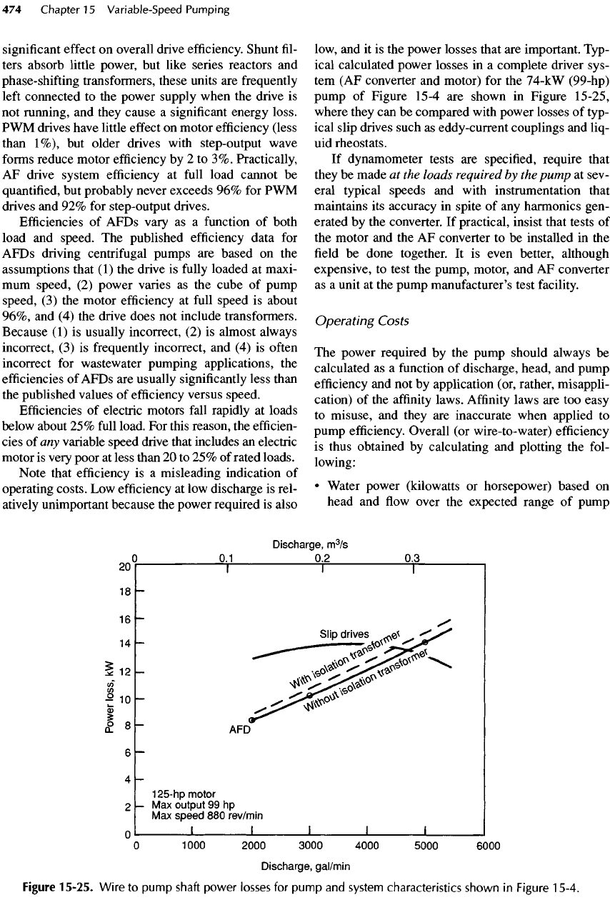
important. Typ-
ical calculated power
losses
in a
complete driver sys-
tem (AF
converter
and
motor)
for the
74-kW (99-hp)
pump
of
Figure 15-4
are
shown
in
Figure 15-25,
where they
can be
compared with power
losses
of
typ-
ical slip drives such
as
eddy-current couplings
and
liq-
uid
rheostats.
If
dynamometer tests
are
specified, require that
they
be
made
at the
loads
required
by the
pump
at
sev-
eral typical speeds
and
with instrumentation that
maintains
its
accuracy
in
spite
of any
harmonics gen-
erated
by the
converter.
If
practical, insist that tests
of
the
motor
and the AF
converter
to be
installed
in the
field be
done together.
It is
even better, although
expensive,
to
test
the
pump, motor,
and AF
converter
as
a
unit
at the
pump manufacturer's test facility.
Operating
Costs
The
power required
by the
pump should always
be
calculated
as a
function
of
discharge, head,
and
pump
efficiency
and not by
application (or, rather, misappli-
cation)
of the
affinity
laws.
Affinity
laws
are too
easy
to
misuse,
and
they
are
inaccurate when applied
to
pump
efficiency.
Overall
(or
wire-to-water)
efficiency
is
thus obtained
by
calculating
and
plotting
the
fol-
lowing:
•
Water power (kilowatts
or
horsepower) based
on
head
and flow
over
the
expected range
of
pump
Figure
15-25.
Wire
to
pump
shaft
power
losses
for
pump
and
system characteristics
shown
in
Figure
15-4.
