Pumping Station Desing - Second Edition by Robert L. Sanks, George Tchobahoglous, Garr M. Jones
Подождите немного. Документ загружается.

C/S and V/S
drives.
Such
a mix can be
successful only
if
the V/S
pumps
are
larger than
the C/S
pumps.
The
reasons
are
given
in the
following subsections.
If,
however,
all of the
pumps
are to be of the
same size,
a
mix
will neither save money
nor be
successful,
as
explained
by the
following reasoning.
Many,
perhaps most, pumping requirements
can be
satisfied
with
two
duty pumps
and a
standby.
If any of
the
pumps
has a V/S
drive,
the
standby must have
a V/S
drive also,
so
only
one
pump
can be a C/S
unit. Assume
each pump
has a
capacity
of 100
units. Below
100
units
only
a V/S
pump
can
operate. Suppose
the flow is
slightly
more than
100
(e.g., 102),
and the C/S
pump
is
started.
The C/S
unit
can
discharge nothing
but 100
units,
so the V/S
pump must
either
slow
to 2
units
or
cycle
on and off at its
minimum desirable
speed.
Cen-
trifugal
pumps cannot tolerate less than
30 or 35% of
their maximum capacity without excessive vibration,
cavitation,
and
damage
to
bearings
and
shafts.
As the
standby
cannot
be
involved (consider
it out of
service),
the
only solution (for discharge
to
equal
influent)
is to
add a
fourth pump
and
only
a V/S
will
do. Now we
have
three
V/S
drives
and one C/S
drive plus
a
larger
dry
well with more piping.
No
savings
there!
If the V/S
pump
is
allowed
to
cycle
on and
off,
the
discharge
surges
and the wet
well must
be
made large enough
for
adequate pump cycle
periods.
In
a
second example, assume
the
peak
influent
rate
is 300
units
and
that most
of the
time
the
influent
rate
ranges between one-ninth
and
one-fifth
of the
peak
flow
—
a
situation that could easily
be met
with
four
identical
V/S
pumps (one
a
standby).
As the flow
increases
from
33
units, only
one
pump would
be
used
until
the flow
reaches
100,
and
then
a
second pump
would
come
on at 50
units
and the first
pump would
drop
to 50
units
also.
If the flow
were
to
drop,
the two
pumps would continue running until
the flow
dropped
to
95 (or
perhaps
to 90) to
avoid switching pumps
on
and off too
frequently. When
the flow rises to
200,
three pumps
are
activated
at 67
units each
and
they
remain
on
until
the flow
drops
to 190 (or
perhaps
to
180). Except
for
very
low flows, a
pump
is
never
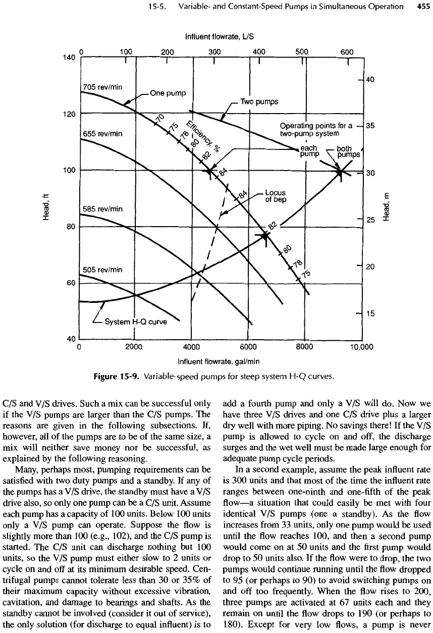
Figure
15-9.
Variable-speed pumps
for
steep system
H-Q
curves.
required
to
operate below
45% of its
capacity.
The
regime
is
shown
in
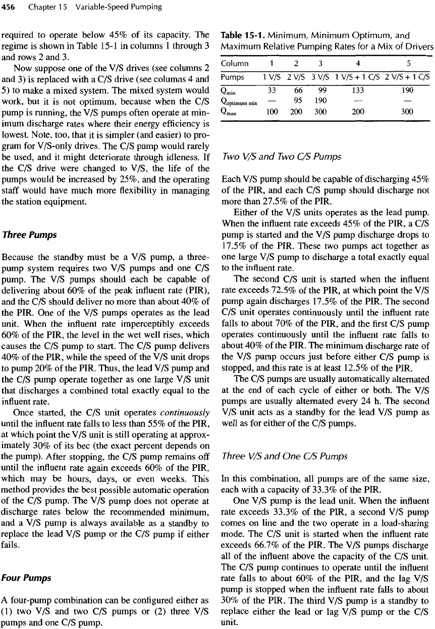
Table
15-1
in
columns
1
through
3
and
rows
2 and 3.
Now
suppose
one of the V/S
drives (see columns
2
and
3) is
replaced with
a C/S
drive (see columns
4 and
5)
to
make
a
mixed system.
The
mixed system would
work,
but it is not
optimum, because when
the C/S
pump
is
running,
the V/S
pumps
often
operate
at
min-
imum
discharge rates where their energy
efficiency
is
lowest.
Note, too, that
it is
simpler (and easier)
to
pro-
gram
for
V/S
-only
drives.
The C/S
pump would rarely
be
used,
and it
might deteriorate through idleness.
If
the
C/S
drive were changed
to
V/S,
the
life
of the
pumps
would
be
increased
by
25%,
and the
operating
staff
would have much more
flexibility
in
managing
the
station equipment.
Three Pumps
Because
the
standby must
be a V/S
pump,
a
three-
pump
system requires
two V/S
pumps
and one C/S
pump.
The V/S
pumps should each
be
capable
of
delivering about
60% of the
peak
influent
rate (PIR),
and
the C/S
should deliver
no
more than about
40% of
the
PIR.
One of the V/S
pumps operates
as the
lead
unit.
When
the
influent
rate imperceptibly exceeds
60% of the
PIR,
the
level
in the wet
well
rises,
which
causes
the C/S
pump
to
start.
The C/S
pump delivers
40% of the
PIR, while
the
speed
of the V/S
unit
drops
to
pump
20% of the
PIR. Thus,
the
lead
V/S
pump
and
the
C/S
pump operate together
as one
large
V/S
unit
that
discharges
a
combined total exactly equal
to the
influent
rate.
Once started,
the C/S
unit operates continuously
until
the
influent
rate
falls
to
less
than
55% of the
PIR,
at
which point
the V/S
unit
is
still operating
at
approx-
imately
30% of its
bee
(the exact percent depends
on
the
pump).
After
stopping,
the C/S
pump remains
off
until
the
influent
rate again exceeds
60% of the
PIR,
which
may be
hours, days,
or
even weeks. This
method
provides
the
best possible automatic operation
of
the C/S
pump.
The V/S
pump does
not
operate
at
discharge rates below
the
recommended minimum,
and
a V/S
pump
is
always available
as a
standby
to
replace
the
lead
V/S
pump
or the C/S
pump
if
either
fails.
Four
Pumps
A
four-pump combination
can be
configured
either
as
(1)
two V/S and two C/S
pumps
or (2)
three
V/S
pumps
and one C/S
pump.
Table
15-1.
Minimum,
Minimum
Optimum,
and
Maximum
Relative
Pumping
Rates
for a Mix of
Drivers
Column
1234
5
Pumps
1 V/S 2 V/S 3 V/S 1 V/S + 1 C/S 2 V/S + 1 C/S
Q
min
33 66 99 133 190
O
Q*
IQO
^optimum
min
~
J
L
^
u
Qmax
100 200 300 200 300
Two V/S and Two C/S
Pumps
Each
V/S
pump should
be
capable
of
discharging
45%
of
the
PIR,
and
each
C/S
pump should discharge
not
more than 27.5%
of the
PIR.
Either
of the V/S
units operates
as the
lead pump.
When
the
influent
rate exceeds
45% of the
PIR,
a C/S
pump
is
started
and the V/S
pump discharge drops
to
17.5%
of the
PIR. These
two
pumps
act
together
as
one
large
V/S
pump
to
discharge
a
total exactly equal
to the
influent
rate.
The
second
C/S
unit
is
started when
the
influent
rate exceeds 72.5%
of the
PIR,
at
which point
the V/S
pump
again discharges 17.5%
of the
PIR.
The
second
C/S
unit operates continuously until
the
influent
rate
falls
to
about
70% of the
PIR,
and the first C/S
pump
operates continuously until
the
influent
rate
falls
to
about
40% of the
PIR.
The
minimum discharge rate
of
the V/S
pump
occurs
just before
either
C/S
pump
is
stopped,
and
this rate
is at
least 12.5%
of the
PIR.
The C/S
pumps
are
usually automatically alternated
at
the end of
each cycle
of
either
or
both.
The V/S
pumps
are
usually alternated every
24 h. The
second
V/S
unit acts
as a
standby
for the
lead
V/S
pump
as
well
as for
either
of the C/S
pumps.
Three
V/S
and One C/S
Pumps
In
this combination,
all
pumps
are of the
same size,
each with
a
capacity
of
33.3%
of the
PIR.
One V/S
pump
is the
lead unit. When
the
influent
rate exceeds 33.3%
of the
PIR,
a
second
V/S
pump
comes
on
line
and the two
operate
in a
load-sharing
mode.
The C/S
unit
is
started when
the
influent
rate
exceeds
66.7%
of the
PIR.
The V/S
pumps discharge
all of the
influent
above
the
capacity
of the C/S
unit.
The C/S
pump continues
to
operate until
the
influent
rate
falls
to
about
60% of the
PIR,
and the lag V/S
pump
is
stopped when
the
influent
rate
falls
to
about
30%
of the
PIR.
The
third
V/S
pump
is a
standby
to
replace either
the
lead
or lag V/S
pump
or the C/S
unit.
Combination
of
Five
or
More
Pumps
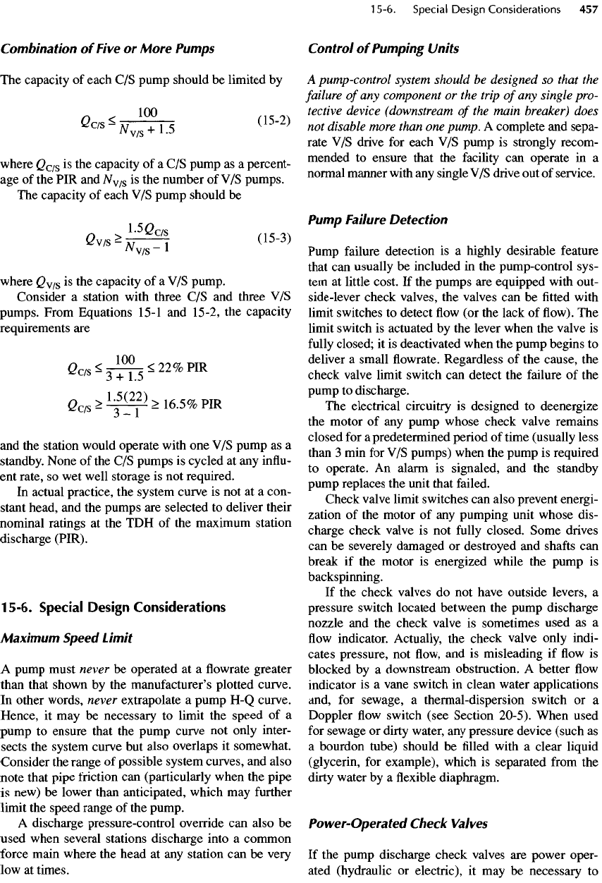
The
capacity
of
each
C/S
pump should
be
limited
by
***H™U
(15
'
2)
where
Q
c/s
is the
capacity
of a C/S
pump
as a
percent-
age of the PIR and
N
v/s
is the
number
of V/S
pumps.
The
capacity
of
each
V/S
pump should
be
l-SGr/s
Q
^~Nl
(15
'
3)
/v
v/s~
L
where
Q
v/s
is the
capacity
of a V/S
pump.
Consider
a
station with three
C/S and
three
V/S
pumps. From Equations
15-1
and
15-2,
the
capacity
requirements
are
100
2c/s
-3TT5-
22%PIR
Q
c/s
>
l
-j^>
16.5%
PIR
and
the
station would operate with
one V/S
pump
as a
standby.
None
of the C/S
pumps
is
cycled
at any
influ-
ent
rate,
so wet
well storage
is not
required.
In
actual practice,
the
system curve
is not at a
con-
stant
head,
and the
pumps
are
selected
to
deliver their
nominal
ratings
at the TDH of the
maximum station
discharge (PIR).
15-6.
Special Design Considerations
Maximum
Speed
Limit
A
pump must never
be
operated
at a flowrate
greater
than
that shown
by the
manufacturer's plotted curve.
In
other words, never extrapolate
a
pump
H-Q
curve.
Hence,
it may be
necessary
to
limit
the
speed
of a
pump
to
ensure that
the
pump curve
not
only inter-
sects
the
system curve
but
also overlaps
it
somewhat.
Consider
the
range
of
possible system curves,
and
also
note that pipe
friction
can
(particularly when
the
pipe
is
new)
be
lower than anticipated, which
may
further
limit
the
speed range
of the
pump.
A
discharge pressure-control override
can
also
be
used
when several stations discharge into
a
common
force
main where
the
head
at any
station
can be
very
low at
times.
Control
of
Pumping
Units
A
pump-control
system
should
be
designed
so
that
the
failure
of
any
component
or the
trip
of
any
single pro-
tective
device
(downstream
of the
main
breaker)
does
not
disable
more
than
one
pump.
A
complete
and
sepa-
rate
V/S
drive
for
each
V/S
pump
is
strongly recom-
mended
to
ensure that
the
facility
can
operate
in a
normal manner with
any
single
V/S
drive
out of
service.
Pump
Failure
Detection
Pump failure detection
is a
highly desirable feature
that
can
usually
be
included
in the
pump-control
sys-
tem
at
little cost.
If the
pumps
are
equipped with out-
side-lever check valves,
the
valves
can be
fitted
with
limit switches
to
detect
flow (or the
lack
of flow). The
limit switch
is
actuated
by the
lever when
the
valve
is
fully
closed;
it is
deactivated when
the
pump begins
to
deliver
a
small
flowrate.
Regardless
of the
cause,
the
check valve limit switch
can
detect
the
failure
of the
pump
to
discharge.
The
electrical circuitry
is
designed
to
deenergize
the
motor
of any
pump whose check valve remains
closed
for a
predetermined period
of
time (usually less
than
3 min for V/S
pumps) when
the
pump
is
required
to
operate.
An
alarm
is
signaled,
and the
standby
pump
replaces
the
unit that failed.
Check valve limit switches
can
also prevent energi-
zation
of the
motor
of any
pumping unit whose
dis-
charge check valve
is not
fully
closed. Some drives
can be
severely damaged
or
destroyed
and
shafts
can
break
if the
motor
is
energized while
the
pump
is
backspinning.
If
the
check valves
do not
have outside levers,
a
pressure switch located between
the
pump discharge
nozzle
and the
check valve
is
sometimes used
as a
flow
indicator. Actually,
the
check valve only indi-
cates pressure,
not flow, and is
misleading
if flow is
blocked
by a
downstream obstruction.
A
better
flow
indicator
is a
vane switch
in
clean water applications
and,
for
sewage,
a
thermal-dispersion switch
or a
Doppler
flow
switch
(see
Section 20-5). When used
for
sewage
or
dirty water,
any
pressure device (such
as
a
bourdon tube) should
be filled
with
a
clear liquid
(glycerin,
for
example), which
is
separated
from
the
dirty
water
by a flexible
diaphragm.
Power-Operated
Check
Valves
If
the
pump discharge check valves
are
power oper-
ated
(hydraulic
or
electric),
it may be
necessary
to
include
a
relatively sophisticated control system
to
protect
the V/S
pump drives against backspinning
while
the
drives
are
energized. When
a
pumping unit
is
required
to
operate
and the
pump drive
is
activated,
the
check valve should
not
begin
to
open until
the
pressure
on the
upstream side
of the
valve exceeds
the
pressure
on the
downstream side. (The pressure
can be
sensed,
as
described previously.) When
the
pump
is no
longer needed,
the
check valve should close
first, and
the
pump should
not be
stopped until
the
valve
is at
least
95%
closed.
The
pumping
unit
should
be
deenergized when
• The
pump discharge pressure does
not
exceed
the
pressure
in the
force
main within
a
short interval
(say,
60 s)
after
the
pump
is
started
• The
check valve does
not
open
fully
within
a few
minutes
after
the
pump discharge pressure exceeds
the
pressure downstream
from
the
check valve
• The
check valve does
not
close
fully
within
a
short
interval (say,
3
min)
after
the
pumping unit
is
sig-
naled
to
shut down.
The
control system should also prevent energiza-
tion
of the
motor
of any
drive whose check valve
is
not
fully
closed.
15-7.
Analysis
of
Variable-Speed Booster
Pumping
The
purpose
of a V/S
booster pump
is to
maintain
a
nearly constant discharge pressure while delivering
the
variable demand
of a
closed distribution network.
Pump speed variation controls
the
pump discharge
pressure,
and the
discharge rate
is
determined
by the
system demand.
To
analyze
the
operation
of a
pump that discharges
into
a
hydraulic network, both
the V/S
pump charac-
teristic curves
and the
curve
of
required pump
differ-
ential head versus demand must
be
considered.
The
pump
must always operate
at the
intersection
of the
impeller's characteristic curve
(at the
speed
of
rota-
tion) with
the
required
differential
head curve.
Pump
Characteristic
Curves
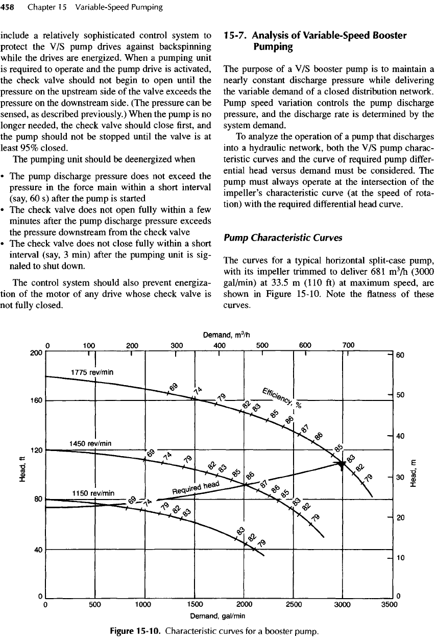
The
curves
for a
typical horizontal split-case pump,
with
its
impeller
trimmed
to
deliver
681
m
3
/h
(3000
gal/min)
at
33.5
m
(110
ft) at
maximum speed,
are
shown
in
Figure
15-10.
Note
the flatness of
these
curves.
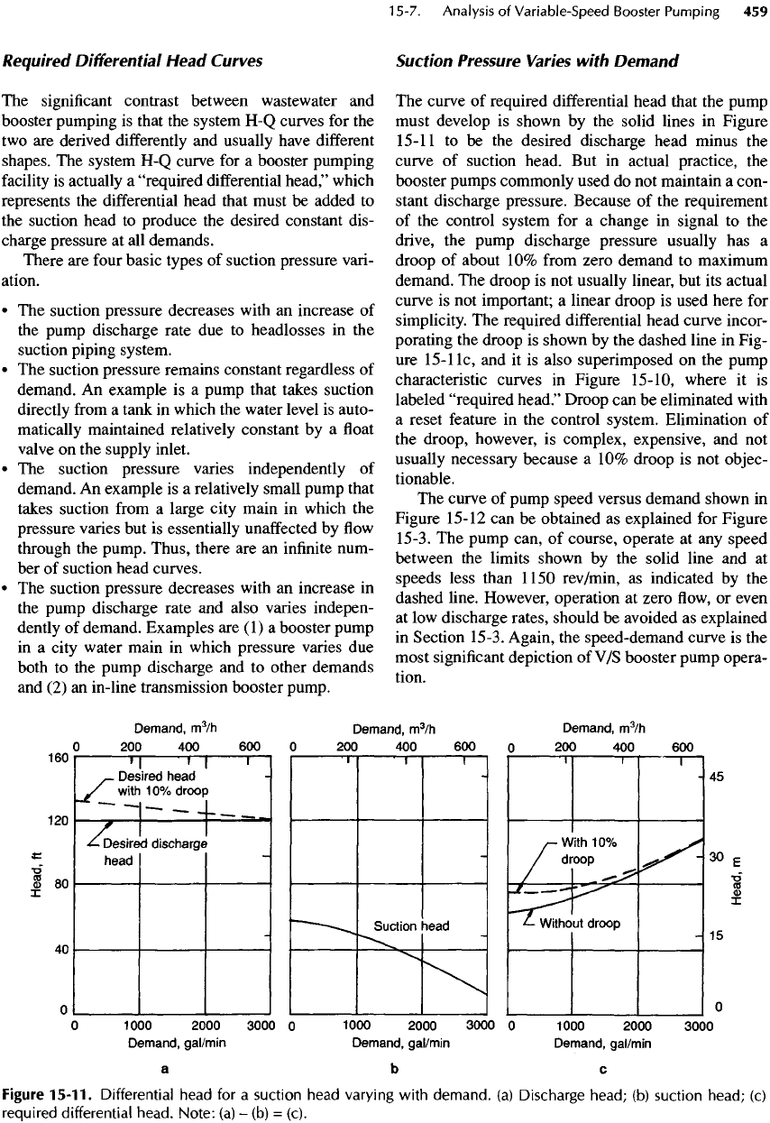
Figure
15-10.
Characteristic curves
for a
booster
pump.
Required
Differential
Head
Curves
The
significant
contrast between wastewater
and
booster pumping
is
that
the
system
H-Q
curves
for the
two are
derived
differently
and
usually have
different
shapes.
The
system
H-Q
curve
for a
booster
pumping
facility
is
actually
a
"required
differential
head,"
which
represents
the
differential
head that must
be
added
to
the
suction head
to
produce
the
desired
constant
dis-
charge pressure
at all
demands.
There
are
four
basic types
of
suction pressure vari-
ation.
• The
suction pressure decreases with
an
increase
of
the
pump discharge rate
due to
headlosses
in the
suction
piping system.
• The
suction pressure remains constant regardless
of
demand.
An
example
is a
pump that takes suction
directly
from
a
tank
in
which
the
water level
is
auto-
matically
maintained relatively constant
by a float
valve
on the
supply inlet.
• The
suction pressure varies independently
of
demand.
An
example
is a
relatively small pump that
takes suction
from
a
large city main
in
which
the
pressure varies
but is
essentially
unaffected
by flow
through
the
pump. Thus, there
are an
infinite
num-
ber of
suction head curves.
• The
suction pressure decreases with
an
increase
in
the
pump discharge rate
and
also varies indepen-
dently
of
demand. Examples
are (1) a
booster pump
in
a
city water main
in
which pressure varies
due
both
to the
pump discharge
and to
other demands
and
(2) an
in-line transmission booster pump.
Suction
Pressure
Varies
with
Demand
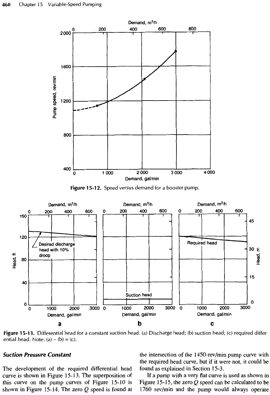
The
curve
of
required differential head that
the
pump
must
develop
is
shown
by the
solid lines
in
Figure
15-11
to be the
desired discharge head minus
the
curve
of
suction
head.
But in
actual
practice,
the
booster pumps commonly used
do not
maintain
a
con-
stant
discharge pressure. Because
of the
requirement
of
the
control system
for a
change
in
signal
to the
drive,
the
pump discharge pressure usually
has a
droop
of
about
10%
from
zero demand
to
maximum
demand.
The
droop
is not
usually linear,
but its
actual
curve
is not
important;
a
linear droop
is
used here
for
simplicity.
The
required
differential
head curve incor-
porating
the
droop
is
shown
by the
dashed line
in
Fig-
ure
15-
11
c, and it is
also superimposed
on the
pump
characteristic curves
in
Figure
15-10,
where
it is
labeled
"required
head."
Droop
can be
eliminated with
a
reset feature
in the
control system. Elimination
of
the
droop, however,
is
complex, expensive,
and not
usually
necessary because
a 10%
droop
is not
objec-
tionable.
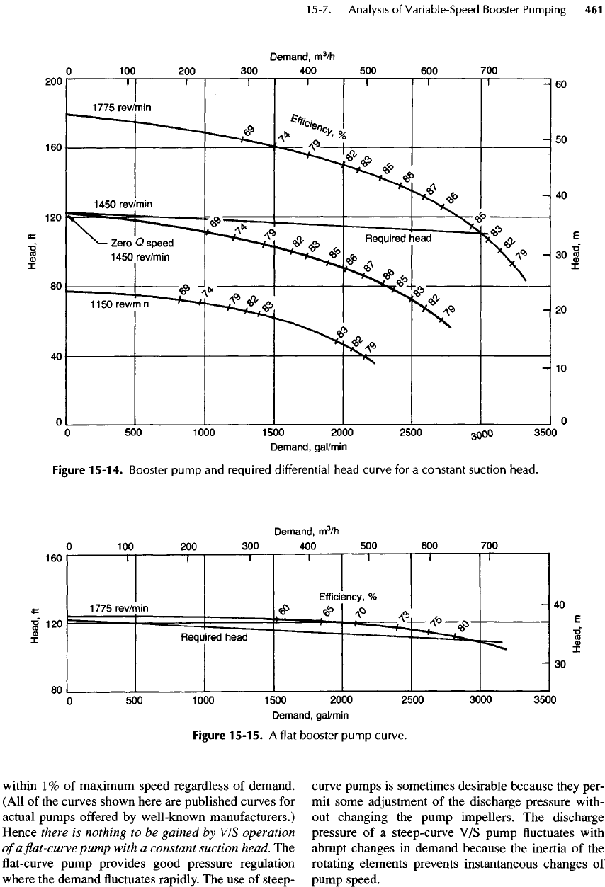
The
curve
of
pump
speed
versus demand shown
in
Figure
15-12
can be
obtained
as
explained
for
Figure
15-3.
The
pump
can,
of
course, operate
at any
speed
between
the
limits shown
by the
solid line
and at
speeds less than
1150
rev/min,
as
indicated
by
the
dashed
line.
However, operation
at
zero
flow, or
even
at
low
discharge
rates,
should
be
avoided
as
explained
in
Section 15-3. Again,
the
speed-demand curve
is the
most
significant
depiction
of V/S
booster pump opera-
tion.
Figure
15-11.
Differential head
for a
suction head varying
with
demand,
(a)
Discharge head;
(b)
suction head;
(c)
required differential head.
Note:
(a) - (b)
=
(c).
Suction
Pressure
Constant
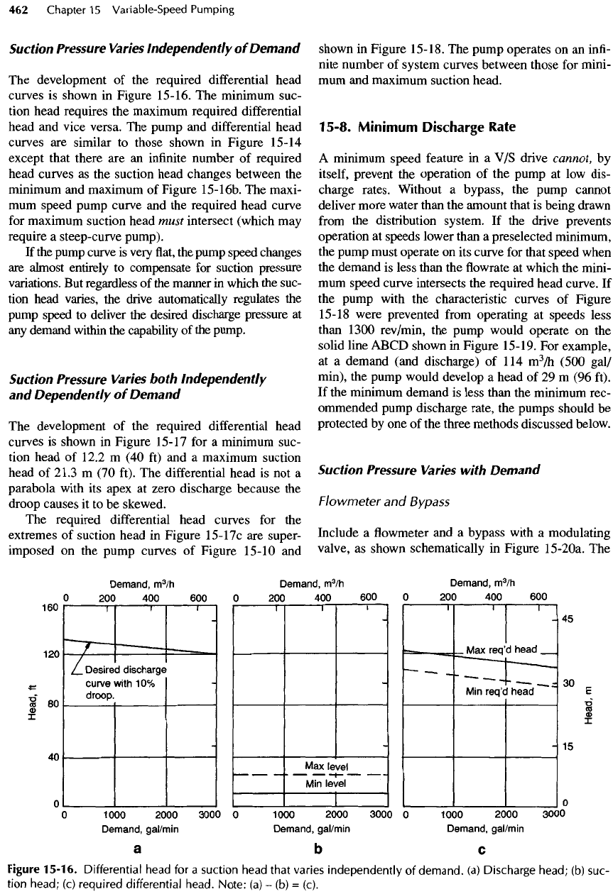
The
development
of the
required differential head
curve
is
shown
in
Figure
15-13.
The
superposition
of
this
curve
on the
pump curves
of
Figure 15-10
is
shown
in
Figure 15-14.
The
zero
Q
speed
is
found
at
the
intersection
of the
1450-rev/min
pump curve with
the
required head curve,
but if it
were not,
it
could
be
found
as
explained
in
Section 15-3.
If
a
pump with
a
very
flat
curve
is
used
as
shown
in
Figure
15-15,
the
zero
Q
speed
can be
calculated
to be
1760
rev/min
and the
pump would always operate
Figure
15-13.
Differential
head
for a
constant
suction
head,
(a)
Discharge
head;
(b)
suction
head;
(c)
required
differ-
ential
head.
Note:
(a)
- (b) =
(c).
Figure
15-12.
Speed versus
demand
for a
booster
pump.
within
1% of
maximum speed regardless
of
demand.
(All
of the
curves shown here
are
published curves
for
actual
pumps
offered
by
well-known manufacturers.)
Hence
there
is
nothing
to be
gained
by
VIS
operation
of
a flat-curve
pump
with
a
constant suction head.
The
flat-curve
pump
provides good pressure regulation
where
the
demand
fluctuates
rapidly.
The use of
steep-
curve pumps
is
sometimes desirable because they per-
mit
some adjustment
of the
discharge pressure with-
out
changing
the
pump
impellers.
The
discharge
pressure
of a
steep-curve
V/S
pump
fluctuates
with
abrupt
changes
in
demand because
the
inertia
of the
rotating elements prevents instantaneous changes
of
pump
speed.
Figure
15-15.
A
flat
booster
pump
curve.
Figure
15-14.
Booster
pump
and
required
differential
head
curve
for a
constant
suction
head.
Suction
Pressure
Varies
Independently
of
Demand
The
development
of the
required
differential
head
curves
is
shown
in
Figure 15-16.
The
minimum suc-
tion head requires
the
maximum required
differential
head
and
vice versa.
The
pump
and
differential
head
curves
are
similar
to
those shown
in
Figure
15-14
except that there
are an
infinite
number
of
required
head curves
as the
suction head changes between
the
minimum
and
maximum
of
Figure
15-16b.
The
maxi-
mum
speed pump curve
and the
required head curve
for
maximum suction head must
intersect
(which
may
require
a
steep-curve pump).
If
the
pump curve
is
very
flat, the
pump speed changes
are
almost entirely
to
compensate
for
suction pressure
variations.
But
regardless
of the
manner
in
which
the
suc-
tion
head varies,
the
drive automatically regulates
the
pump
speed
to
deliver
the
desired discharge pressure
at
any
demand
within
the
capability
of the
pump.
Suction
Pressure
Varies
both
Independently
and
Dependently
of
Demand
The
development
of the
required differential head
curves
is
shown
in
Figure 15-17
for a
minimum suc-
tion
head
of
12.2
m (40 ft) and a
maximum suction
head
of
21.3
m (70
ft).
The
differential head
is not a
parabola with
its
apex
at
zero discharge because
the
droop causes
it to be
skewed.
The
required
differential
head curves
for the
extremes
of
suction head
in
Figure
15-17c
are
super-
imposed
on the
pump curves
of
Figure 15-10
and
shown
in
Figure
15-18.
The
pump operates
on an
infi-
nite number
of
system curves between those
for
mini-
mum
and
maximum suction head.
15-8.
Minimum
Discharge
Rate
A
minimum speed feature
in a V/S
drive cannot,
by
itself,
prevent
the
operation
of the
pump
at low
dis-
charge rates. Without
a
bypass,
the
pump cannot
deliver more water than
the
amount that
is
being drawn
from
the
distribution system.
If the
drive prevents
operation
at
speeds lower than
a
preselected minimum,
the
pump must operate
on its
curve
for
that speed when
the
demand
is
less than
the flowrate at
which
the
mini-
mum
speed curve intersects
the
required head curve.
If
the
pump with
the
characteristic curves
of
Figure
15-18 were prevented
from
operating
at
speeds less
than
1300 rev/min,
the
pump would operate
on the
solid line ABCD shown
in
Figure 15-19.
For
example,
at
a
demand (and discharge)
of 114
m
3
/h
(500 gal/
min),
the
pump would develop
a
head
of 29 m (96
ft).
If
the
minimum demand
is
less than
the
minimum rec-
ommended pump discharge rate,
the
pumps should
be
protected
by one of the
three methods discussed below.
Suction
Pressure
Varies
with Demand
Flowmeter
and
Bypass
Include
a flowmeter and a
bypass with
a
modulating
valve,
as
shown schematically
in
Figure
15-2Oa.
The
Figure
15-16.
Differential
head
for a
suction head
that
varies
independently
of
demand,
(a)
Discharge
head;
(b)
suc-
tion
head;
(c)
required
differential
head.
Note:
(a) - (b) =
(c).
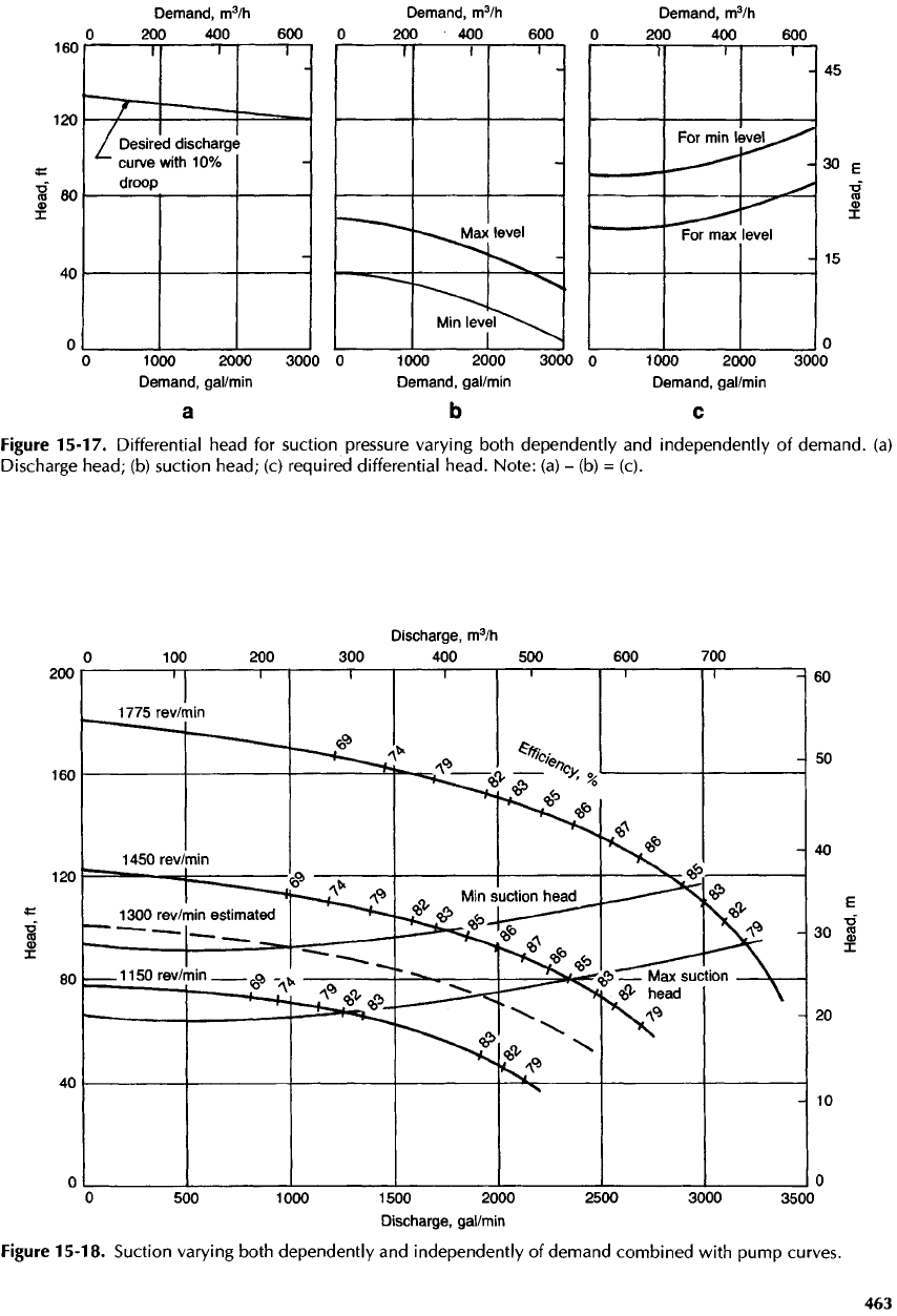
Figure
15-18.
Suction varying both dependently
and
independently
of
demand combined
with
pump
curves.
Figure
15-17.
Differential head
for
suction
pressure
varying both dependently
and
independently
of
demand,
(a)
Discharge
head;
(b)
suction head;
(c)
required differential head. Note:
(a) - (b) =
(c).
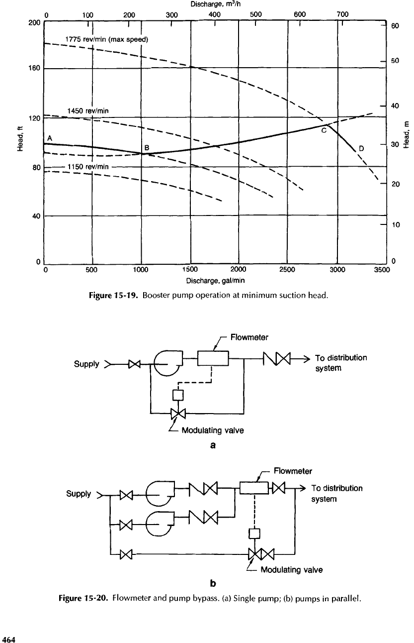
Figure
15-19.
Booster
pump operation
at
minimum suction head.
Figure
15-20. Flowmeter
and
pump
bypass,
(a)
Single
pump;
(b)
pumps
in
parallel.
