Petruzella F.D. Programmable Logic Controllers
Подождите немного. Документ загружается.

Programming Counters Chapter 8 163
time of day or to log data pertaining to the operation of the
process. The logic used to implement a clock as part of a
PLC’s program is straightforward and simple to accom-
plish. A single timer instruction and counter instructions
are all you need.
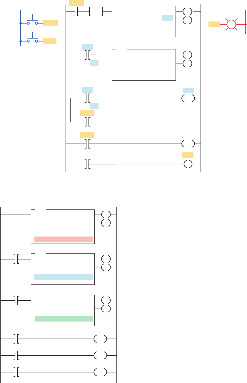
Figure 8-28 illustrates a timer-counter program that
produces a time-of-day clock measuring time in hours
and minutes. The operation of the program can be sum-
marized as follows:
• An RTO timer instruction (T4:0) is programmed
rst with a preset value of 60 seconds.
• The T4:0 timer times for a 60-s period, after which
its done bit is set.
• This, in turn, causes the up-counter (C5:0) of rung
001 to increment 1 count.
• On the next processor scan, the timer is reset and
begins timing again.
• The C5:0 counter is preset to 60 counts, and each
time the timer completes its time-delay period, its
count is incremented.
• When the C5:0 counter reaches its preset value of
60, its done bit is set.
• This, in turn, causes the up-counter (C5:1) of rung
002, which is preset for 24 counts, to increment
1count.
• Whenever the C5:1 counter reaches its preset value
of 24, its done bit is set to reset itself.
the technique. The operation of the program can be sum-
marized as follows:
• The output of the rst counter is programmed into
the input of the second counter.
• The status bits of both counters are programmed in
series to produce an output.
• These two counters allow twice as many counts to
be measured.
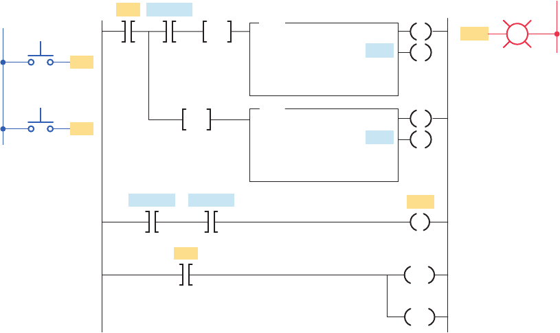
Another method of cascading counters is sometimes
used when an extremely large number of counts must be
stored. For example, if you require a counter to count up
to 250,000, it is possible to achieve this by using only
two counters. Figure 8-27 shows how the two counters
would be programmed for this purpose. The operation of
the program can be summarized as follows:
• Counter C5:1 has a preset value of 500 and counter
C5:2 has a preset value of 500.
• Whenever counter C5:1 reaches 500, its done bit re-
sets counter C5:1 and increments counter C5:2 by 1.
• When the done bit of counter C5:1 has turned
on and off 500 times, the output light becomes
energized. Therefore, the output light turns on after
5003 500, or 250,000, transitions of the count
input.
Some PLCs include a real-time clock as part of their
instruction set. A real-time clock allows you to display the
Figure 8-26 Counting beyond the maximum count.
Ladder logic program
Count
button
Inputs
L1
Light
Light
PB1
B3:0/0
C5:0/DN
C5:1/DN
C5:0/DN
PB2
Output
L2
Reset
button
C5:1
32000
0
CTU
COUNT-UP COUNTER
Counter
Preset
Accumulated
C5:0
32000
0
CTU
COUNT-UP COUNTER
Counter
Preset
Accumulated
C5:0
C5:1
PB1
PB2
CU
DN
CU
DN
RES
RES
OSR
B3:0/0
OSR
pet10882_ch08_149-175.indd 163pet10882_ch08_149-175.indd 163 7/23/10 10:01 PM7/23/10 10:01 PM
164 Chapter 8 Programming Counters
• The time of day is generated by examining the cur-
rent, or accumulated, count or time for each counter
and the timer.
• Counter C5:1 indicates the hour of the day in
24-h military format, while the current minutes
are represented by the accumulated count value of
counter C5:0.
• The timer displays the seconds of a minute as its
current, or accumulated, time value.
The 24-hour clock can be used to record the time of
an event. Figure8-29 illustrates the principle of this tech-
nique. In this application the time of the opening of a
pressure switch is to be recorded. The operation of the
program can be summarized as follows:
• The circuit is set into operation by pressing the reset
button and setting the clock for the time of day.
• This starts the 24-hour clock and switches the set
indicating light on.
• Should the pressure switch open at any time, the
clock will automatically stop and the trip indicating
light will switch on.
• The clock can then be read to determine the time of
opening of the pressure switch.
Figure 8-28 24-hour clock program.
001
002
003
004
005
RTO
RETENTIVE TIMER ON
Timer
Time base
Preset
Accumulated
T4:0
1.0
60
0
CTU
COUNT-UP COUNTER
Counter
Preset
Accumulated
C5:0
60
0
CTU
COUNT-UP COUNTER
Counter
Preset
Accumulated
C5:1
24
0
000
T4:0
C5:0
C5:1
Ladder logic program
Seconds
T4:0/DN
T4:0/DN
C5:0/DN
C5:0/DN
C5:1/DN
Minutes
Hours
EN
CU
CU
DN
DN
DN
RES
RES
RES
Figure 8-27 Cascading counters for extremely large counts.
Ladder logic program
Reset
Reset
Reset
C5:1
PB1
PB2
Inputs
L1
Count
Count
Output
L2
CTU
COUNT-UP COUNTER
Counter
Preset
Accumulated
C5:1
500
0
C5:1
DN
C5:1
DN
CTU
COUNT-UP COUNTER
Counter
Preset
Accumulated
C5:2
500
0
C5:2
DN
C5:2
CU
DN
CU
DN
RES
RES
Light
Light
B3:0/0
OSR
pet10882_ch08_149-175.indd 164pet10882_ch08_149-175.indd 164 7/23/10 10:01 PM7/23/10 10:01 PM
Programming Counters Chapter 8 165
Figure8-31 illustrates an example of cutting objects to
a speci ed length. The object is advanced for a speci ed
distance and measured by encoder pulses to determine the
correct length for cutting.
Figure8-32 shows a counter program used for length
measurement. This system accumulates the total length
of random pieces of bar stock moved on a conveyor.
The operation of the program can be summarized as
follows:
• Count input pulses are generated by the magnetic
sensor, which detects passing teeth on a conveyor
drive sprocket.
8.5 Incremental Encoder-Counter
Applications
The incremental optical encoder shown in Figure 8-30
creates a series of square waves as its shaft is rotated. The
encoder disk interrupts the light as the encoder shaft is
rotated to produce the square wave output waveform.
The number of square waves obtained from the output of
the encoder can be made to correspond to the mechanical
movement required. For example, to divide a shaft revolu-
tion into 100 parts, an encoder could be selected to supply
100 square wave-cycles per revolution. By using a counter to
count those cycles, we could tell how far the shaft had rotated.
Figure 8-29 Monitoring the time of an event.
Ladder logic program
Internal
B3:0/0
Internal
B3:0/0
Set
Outputs
L2
Set
Trip
Pressure
switch
Pressure
switch
Inputs
L1
Reset
Reset
Internal
B3:0/0
Trip
Internal
B3:0/0
Internal
B3:0/0
RTO
RETENTIVE TIMER ON
Timer
Time base
Preset
Accumulated
T4:0
1.0
60
0
CTU
COUNT-UP COUNTER
Counter
Preset
Accumulated
C5:1
24
0
Seconds
C5:0/DN
C5:0/DN
C5:1/DN
CTU
COUNT-UP COUNTER
Counter
Preset
Accumulated
C5:0
60
0
T4:0/DN
T4:0/DN
Minutes
Hours
C5:1
C5:0
T4:0
EN
CU
CU
DN
DN
DN
RES
RES
RES
pet10882_ch08_149-175.indd 165pet10882_ch08_149-175.indd 165 7/23/10 10:01 PM7/23/10 10:01 PM
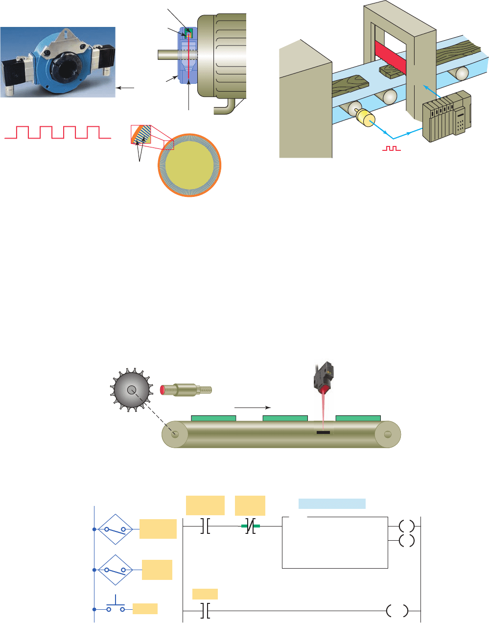
166 Chapter 8 Programming Counters
counter to accumulate counts only when bar stock
is moving.
• The counter is reset by closing the reset button.
8.6 Combining Counter
and Timer Functions
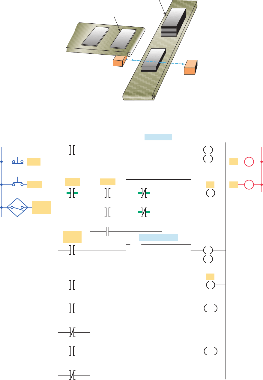
Many PLC applications use both the counter function and
the timer function. Figure 8-33 illustrates an automatic
stacking program that requires both a timer and counter.
• If 10 teeth per foot of conveyor motion pass the
sensor, the accumulated count of the counter would
indicate feet in tenths.
• The photoelectric sensor monitors a reference
point on the conveyor. When activated, it pre-
vents the unit from counting, thus permitting the
Figure 8-31 Cutting objects to a specifi ed length.
Pulses
Rotary
encoder
Programmable
controller
Wood
Cutter
control
Figure 8-30 Optical incremental encoder.
Source: Photo courtesy Avtron, www.avtron.com.
Optical
encoder
Generated pulses
Optical
sensor
Light
source
Optical
disk
Lines
Figure 8-32 Counter used for length measurement. (a) Process. (b) Program.
(a)
Magnetic
sensor
Sprocket
Conveyor
Reflector
Photoelectric
sensor
f
l
(b)
Ladder logic program
CTU
COUNT-UP COUNTER
Counter
Preset
Accumulated
C5:1
10
0
C5:1
Magnetic
sensor
Inputs
Photo
sensor
L1
10 counts per foot
Magnetic
sensor
Reset
Reset
Photo
sensor
CU
DN
RES
pet10882_ch08_149-175.indd 166pet10882_ch08_149-175.indd 166 7/23/10 10:01 PM7/23/10 10:01 PM
Programming Counters Chapter 8 167
Figure 8-33 Automatic stacking program. (a) Process. (b) Program.
(b)
Ladder logic program
Outputs
L2
Stop
M2
C5:1
TON
TIMER ON DELAY
Timer
Time base
Preset
Accumulated
T4:1
1.0
5
0
CTU
COUNT-UP COUNTER
Counter
Preset
Accumulated
C5:1
15
0
T4:1
DN
T4:1
DN
Stop
T4:1
C5:1
DN
M1 M2
M1
M1
M2
M2
T4:1
DN
M2
Photo
sensor
Photo
sensor
Stop
Stop
Start
Start
Inputs
L1
M2 run time
Number of plates
EN
CU
DN
DN
RES
RES
(a)
Complete stack
Metal plates
M1
Conveyor
M2
Conveyor
Light
source
Sensor
pet10882_ch08_149-175.indd 167pet10882_ch08_149-175.indd 167 7/23/10 10:01 PM7/23/10 10:01 PM
168 Chapter 8 Programming Counters
• After 15 plates have been stacked, conveyor M1
stops and conveyor M2 begins running.
• After conveyor M2 has been operated for 5 s, it
stops and the sequence is repeated automatically.
• The done bit of the timer resets the timer and the
counter and provides a momentary pulse to auto-
matically restart conveyor M1.
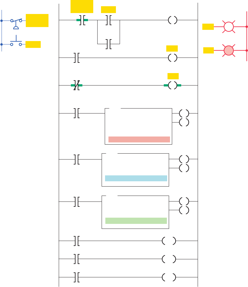
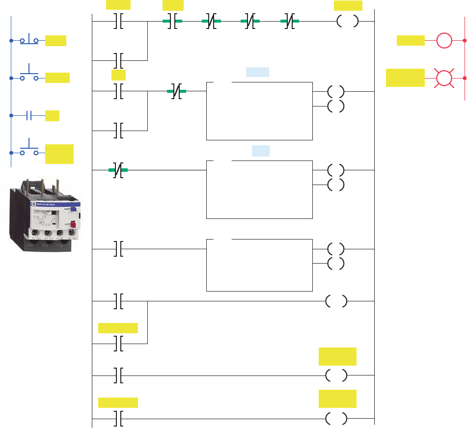
Figure 8-34 shows a motor lock-out program. This
program is designed to prevent a machine operator from
In this process, conveyor M1 is used to stack metal plates
onto conveyor M2. The photoelectric sensor provides an
input pulse to the PLC counter each time a metal plate
drops from conveyor M1 to M2. When 15 plates have
been stacked, conveyor M2 is activated for 5 s by the PLC
timer. The operation of the program can be summarized
as follows:
• When the start button is pressed, conveyor M1
begins running.
Figure 8-34 Motor lock-out program.
Source: This material and associated copyrights are proprietary to, and used with the permission of Schneider Electric.
Ladder logic program
Outputs
L2
Reset-PB
Reset-PB
C5:0
RES
TON
TIMER ON DELAY
Timer
Time base
Preset
Accumulated
T4:0
1
300
0
EN
5 min
DN
TON
TIMER ON DELAY
Timer
Time base
Preset
Accumulated
T4:1
1
3600
0
EN
1 hr
DN
CTU
COUNT-UP COUNTER
Counter
Preset
Accumulated
C5:0
6
0
CU
DN
T4:0
EN
T4:0
EN
T4:1
DN
T4:1
DN
C5:0
DN
L
L
U
Motor
Motor
Motor
OL
Lock-out
light
Lock-out
light
Lock-out
light
OL
OL
Reset
PB
OL relay
Stop
Stop
Start
Start
Inputs
L1
OL
T4:0
DN
Lock-out
light
pet10882_ch08_149-175.indd 168pet10882_ch08_149-175.indd 168 7/23/10 10:01 PM7/23/10 10:01 PM
Programming Counters Chapter 8 169
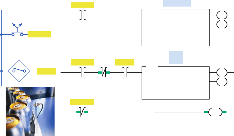
• Sensor pulses continue but do not affect the PLC
counter.
• The number of parts for the past minute is repre-
sented by the accumulated value of the counter.
• The sequence is reset by momentarily opening and
closing the start switch.
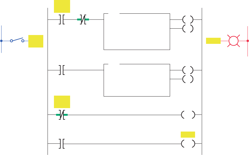
A timer is sometimes used to drive a counter when
an extremely long time-delay period is required. For
example, if you require a timer to time to 1,000,000 s,
you can achieve this by using a single timer and counter.
Figure8-36 shows how the timer and counter would be
programmed for such a purpose. The operation of the pro-
gram can be summarized as follows:
• Timer T4:0 has a preset value of 10,000, and coun-
ter C5:0 has a preset value of 100.
• Each time the timer T4:0 input contact closes for
10,000 s, its done bit resets timer T4:0 and incre-
ments counter C5:0 by 1.
• When the done bit of timer T4:0 has turned on
and off 100 times, the output light becomes
energized.
• Therefore, the output light turns on after 10,000 3
100, or 1,000,000, seconds after the timer input
contact closes.
starting a motor that has tripped off more than 5 times in
an hour. The operation of the program can be summarized
as follows:
• The normally open overload (OL) relay contact
momentarily closes each time an overload current is
sensed.
• Every time the motor stops due to an overload con-
dition, the motor start circuit is locked out for 5min.
• If the motor trips off more than 5 times in an hour,
the motor start circuit is permanently locked out and
cannot be started until the reset button is actuated.
• The lock-out pilot light is switched on whenever a
permanent lock-out condition exists.
Figure 8-35 shows a product part ow rate program.
This program is designed to indicate how many parts pass
a given process point per minute. The operation of the
program can be summarized as follows:
• When the start switch is closed, both the timer and
counter are enabled.
• The counter is pulsed for each part that passes the
parts sensor.
• The counting begins and the timer starts timing
through its 1-minute time interval.
• At the end of 1 minute, the timer done bit causes the
counter rung to go false.
Figure 8-35 Product fl ow rate program.
Source: Photo courtesy Omron Industrial Automation, www.ia.omron.com.
Ladder logic program
TON
TIMER ON DELAY
Timer
Time base
Preset
Accumulated
T4:1
1.0
60
0
EN
DN
CTU
COUNT-UP COUNTER
Counter
Preset
Accumulated
C5:1
0
0
CU
DN
Inputs
L1
Start SW
Start SW
Start SW
Sensor
Off On
Total
parts
1 min timer
T4:1
DN
C5:1
RES
Start SW
Sensor
pet10882_ch08_149-175.indd 169pet10882_ch08_149-175.indd 169 7/23/10 10:01 PM7/23/10 10:01 PM
170 Chapter 8 Programming Counters
Figure 8-36 Timer driving a counter to produce an extremely long time-delay period.
Ladder logic program
Timer
input
Timer
input
Timer
input
Input
L1
S1
Light
Output
L2
Light
TON
TIMER ON DELAY
Timer
Time base
Preset
Accumulated
T4:0
1.0
10000
0
EN
DN
CTU
COUNT-UP COUNTER
Counter
Preset
Accumulated
C5:0
100
0
CU
DN
C5:0
DN
T4:0
DN
T4:0
DN
C5:0
RES
pet10882_ch08_149-175.indd 170pet10882_ch08_149-175.indd 170 7/23/10 10:02 PM7/23/10 10:02 PM
Programming Counters Chapter 8 171
1. Name the three forms of PLC counter instructions,
and explain the basic operation of each.
2. State four pieces of information usually associated
with a PLC counter instruction.
3. In a PLC counter instruction, what rule applies to
the addressing of the counter and reset instructions?
4. When is the output of a PLC counter energized?
5. When does the PLC counter instruction increment
or decrement its current count?
6. The counter instructions of PLCs are normally
retentive. Explain what this means.
7 . a . Compare the operation of a standard Examine-
on contact instruction with that of an off-to-on
transitional contact.
b. What is the normal function of a transitional
contact used in conjunction with a counter?
8. Explain how an OSR (one-shot rising) instruction
can be used to freeze rapidly changing data.
9. Identify the type of counter you would choose for
each of the following situations:
a. Count the total number of parts made during
each shift.
b. Keep track of the current number of parts in a
stage of a process as they enter and exit.
c. There are 10 parts in a full hopper. As parts
leave, keep track of the number of parts remain-
ing in the hopper
10. Describe the basic programming process involved
in the cascading of two counters.
11. a. When is the over ow bit of an up-counter
set?
b. When is the under ow bit of a down-counter
set?
12. Describe two common applications for counters.
13. What determines the maximum speed of transitions
that a PLC counter can count? Why?
CHAPTER 8 REVIEW QUESTIONS
Figure 8-37 Program for Problem 1.
Ladder logic program
I:1/1
CTU
COUNT-UP COUNTER
Counter
Preset
Accumulated
C5:1
50
0
CU
DN
C5:1/DN
O:2/0
C5:1/DN O:2/1
I:1/2 C5:1
Res
Rung 1
Rung 2
Rung 3
Rung 4
1. Study the ladder logic program in Figure8-37 , and
answer the questions that follow:
a. What type of counter has been programmed?
b. When would output O:2/0 be energized?
c. When would output O:2/1 be energized?
d. Suppose your accumulated value is 24 and you
lose ac line power to the controller. When power
is restored to your controller, what will your ac-
cumulated value be?
e. Rung 4 goes true and while it is true, rung 1
goes through ve false-to-true transitions of rung
conditions. What is the accumulated value of the
counter after this sequence of events?
f. When will the count be incremented?
g. When will the count be reset?
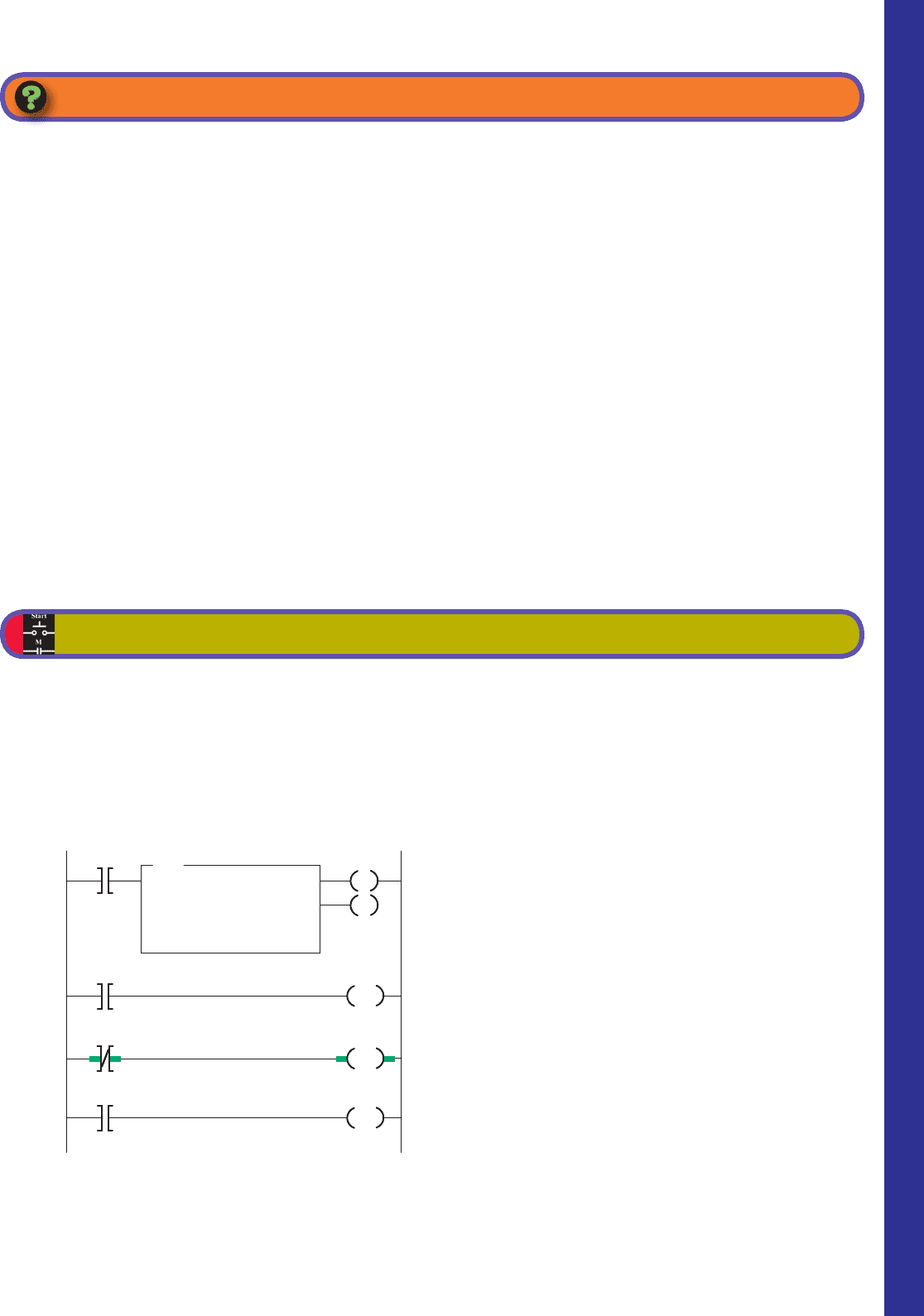
2. Study the ladder logic program in Figure8-38 , and
answer the questions that follow:
a. Suppose the input pushbutton is actuated from
off to on and remains held on. How will the
status of output B3:0/9 be affected?
b. Suppose the input pushbutton is now released to
the normally off position and remains off. How
will the status of output B3:0/9 be affected?
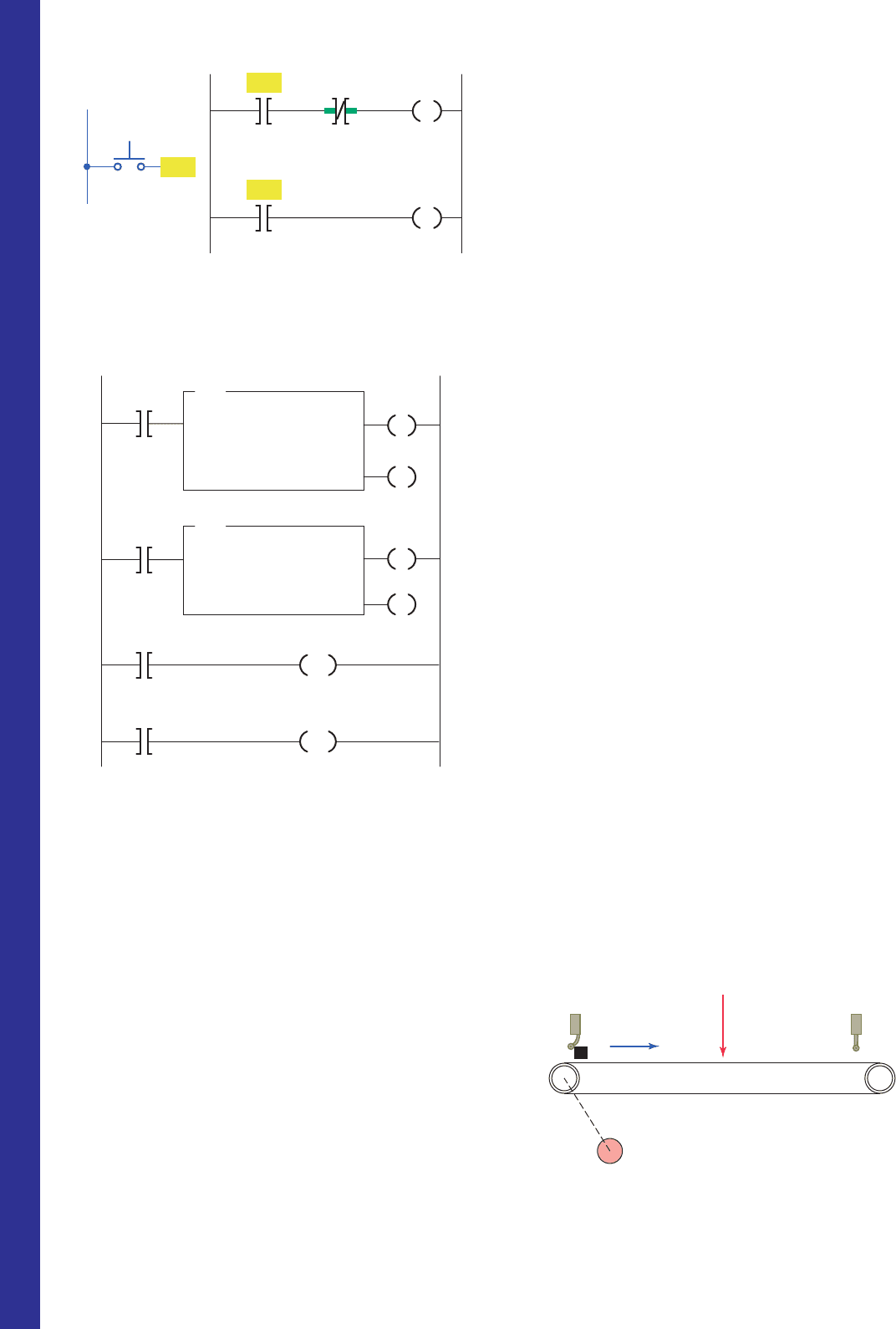
3. Study the ladder logic program in Figure8-39 , and
answer the questions that follow:
a. What type of counter has been programmed?
b. What input address will cause the counter to
increment?
CHAPTER 8 PROBLEMS
pet10882_ch08_149-175.indd 171pet10882_ch08_149-175.indd 171 7/23/10 10:02 PM7/23/10 10:02 PM
172 Chapter 8 Programming Counters
• Turns on a light anytime the accumulated value
of the counter is less than 20.
• Turns on a second light when the accumulated
value of the counter is equal to or greater than 20.
• Resets the counter to 0 when a selector switch is
closed.
5. Design a PLC program and prepare a typical I/O
connection diagram and ladder logic program that
will execute the following control circuit correctly:
• Turns on a nonretentive timer when a switch is
closed (preset value of timer is 10 s).
• Resets timer automatically through a pro-
grammed transitional contact when it times out.
• Counts the number of times the timer goes
to10s.
• Resets counter automatically through a second
programmed transitional contact at a count of 5.
• Latches on a light at the count of 5.
• Resets light to off and counter to 0 when a selec-
tor switch is closed.
6. Design a PLC program and prepare a typical I/O
connection diagram and ladder logic program that
will correctly execute the industrial control process
in Figure8-40 . The sequence of operation is as
follows:
• Product in position (limit switch LS1 contacts
close).
• The start button is pressed and the conveyor
motor starts to move the product forward toward
position A (limit switch LS1 contacts open when
the actuating arm returns to its normal position).
• The conveyor moves the product forward to
position A and stops (position detected by 8 off-
to-on output pulses from the encoder, which are
counted by an up-counter).
• A time delay of 10 s occurs, after which the con-
veyor starts to move the product to limit switch
LS2 and stops (LS2 contacts close when the actu-
ating arm is hit by the product).
c. What input address will cause the counter to
decrement?
d. What input address will reset the counter to a
count of zero?
e. When would output O:6/2 be energized?
f. Suppose the counter is rst reset, and then
input I:2/6 is actuated 15 times and input I:3/8
is actuated 5 times. What is the accumulated
countvalue?
4. Design a PLC program and prepare a typical I/O
connection diagram and ladder logic program for
the following counter speci cations:
• Counts the number of times a pushbutton is
closed.
• Decrements the accumulated value of the counter
each time a second pushbutton is closed.
Figure 8-38 Program for Problem 2.
L1
Input
B3:0/1
B3:0/1
B3:0/9
Input
Input
Figure 8-39 Program for Problem 3.
Ladder logic program
CTU
COUNT-UP COUNTER
Counter
Preset
Accumulated
C5:2
25
0
CU
DN
I:2/6
CTD
COUNT-DOWN COUNTER
Counter
Preset
Accumulated
C5:2
25
0
CU
DN
C5:2
DN
O:6/2
I:3/8
C5:2
RES
I:4/1
Figure 8-40 Control process for Problem 6.
LS1
LS2
Forward
Position
A
Encoder
pet10882_ch08_149-175.indd 172pet10882_ch08_149-175.indd 172 7/23/10 10:02 PM7/23/10 10:02 PM