Petruzella F.D. Programmable Logic Controllers
Подождите немного. Документ загружается.

Programming Timers Chapter 7 133
this reason, this timer is also classi ed as
nonretentive.
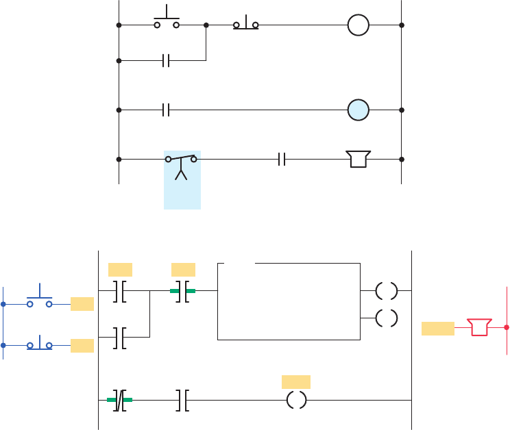
Figure 7-21 illustrates the use of an off-delay timer
instruction used to switch motors off sequentially at
5second intervals. The operation of the program can be
summarized as follows:
• Timer preset values for T4:1, T4:2, and T4:3 are set
for 5 s, 10s, and 15 s, respectively.
• Closing the input switch SW immediately sets the
done bit of each of the three off-delay timers to 1,
immediately turning on motors M1, M2, and M3.
• If SW is then opened, logic continuity to all three
timers is lost and each timer begins counting.
• Timer T4:1 times out after 5 s resetting its done bit
to zero to de-energize motor M1.
• Timer T4:2 times out 5 s later resetting its done bit
to zero to de-energize motor M2.
• Timer T4:3 times out 5 s later resetting its done bit
to zero to de-energize motor M3.
7. 4 Off-Delay Timer Instruction
The off-delay timer (TOF) operation will keep the out-
put energized for a time period after the rung containing
the timer has gone false. Figure7-20 illustrates the pro-
gramming of an off-delay timer that uses the SLC500
TOF timer instruction. If logic continuity is lost, the
timer begins counting time-based intervals until the ac-
cumulated time equals the programmed preset value.
The operation of the circuit can be summarized as
follows:
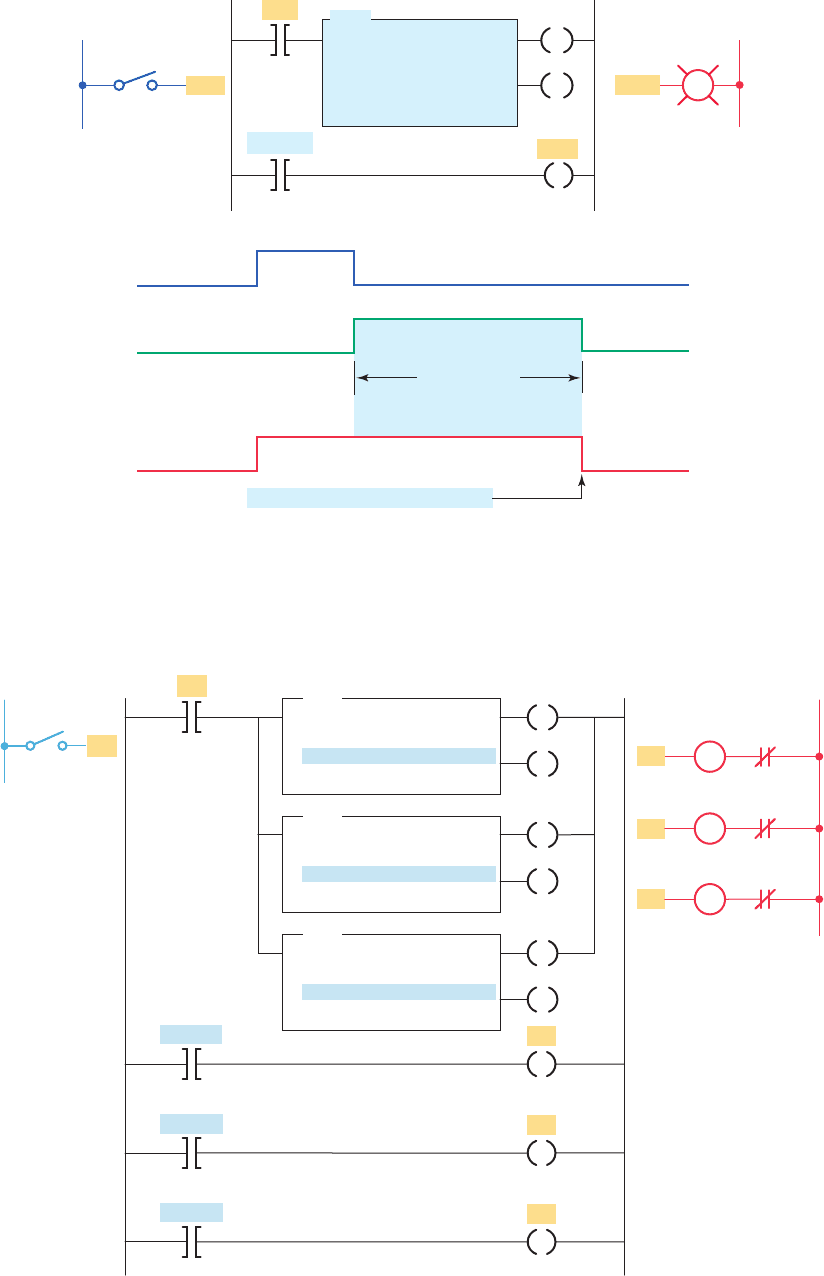
• When the switch connected to input I:1/0 is rst
closed, timed output O:2/1 is set to 1 immediately
and the lamp is switched on.
• If this switch is now opened, logic continuity is lost
and the timer begins counting.
• After 15 s, when the accumulated time equals the
preset time, the output is reset to 0 and the lamp
switches off.
• If logic continuity is gained before the timer is
timed out, the accumulated time is reset to0.For
PB2
Ladder logic program
PB1
L2
Output
Horn
TON
TIMER ON DELAY
Timer T4:0
Time base 1.0
Preset 10
Accumulated 0
L1
Inputs
Start-up
Reset
PB1
PB2
T4:0
EN
Horn
T4:0 T4:0
DN EN
EN
DN
L2L1
PB2PB1
Reset
Hardwired relay circuit
Start-up
CR-3
CR-1
CR-2
Horn
CR
TD
TD-1
(10 s)
Figure 7-18 Conveyor warning signal circuit.
pet10882_ch07_125-148.indd 133pet10882_ch07_125-148.indd 133 7/23/10 9:35 PM7/23/10 9:35 PM
134 Chapter 7 Programming Timers
• As a result, timed contact TD-1 opens to de-
energize motor starter coil M1, timed contact
TD-2 closes to energize motor starter coil M2,
instantaneous contact TD-3 opens to switch the
green light off, and instantaneous contact TD-4
closes to switch the red light on. The circuit
remains in this state as long as limit switch LS1
is closed.
• When limit switch LS1 is opened, the off-delay
timer coil TD de-energizes and the time-delay
period is started.
Figure 7-22 shows how a hardwired off-delay timer
relay circuit with both instantaneous and timed con-
tacts. The operation of the circuit can be summarized as
follows:
• When power is rst applied (limit switch LS open),
motor starter coil M1 is energized and the green
pilot light is on.
• At the same time, motor starter coil M2 is de-
energized, and the red pilot light is off.
• When limit switch LS closes, off-delay timer coil
TD energizes.
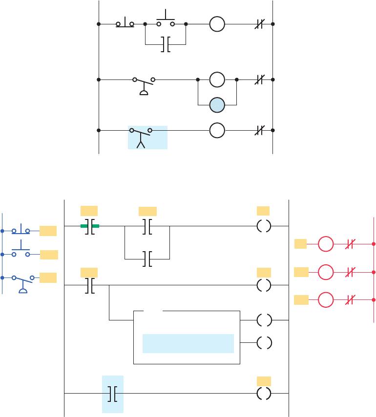
Figure 7-19 Automatic sequential control system.
OL
OL
Start
Hardwired relay circuit
Stop
M1-1
(15 s)
Feed
motor
Main drive
motor
Lube oil
pump motor
(Lube oil
pressure switch)
TD-1
L2L1
PB1
PB2
PS1
OL
M1
M2
TD
M3
PB2
PB1
PS1
L2
OL
Outputs
Ladder logic program
T4:0
1.0
15
0
TON
TIMER ON DELAY
Timer
Time base
Preset
Accumulated
M1
M1
M2
M3
T4:0
DN
PB2
PB1
PS1
L1
Inputs
OL
M3
OL
M2
M1
EN
DN
pet10882_ch07_125-148.indd 134pet10882_ch07_125-148.indd 134 7/23/10 9:35 PM7/23/10 9:35 PM
Programming Timers Chapter 7 135
Figure 7-20 Off-delay programmed timer.
O:2/1
L2
Output
Ladder logic program
I:1/0
L1
Input
S1
TOF
TIMER OFF DELAY
Timer T4:3
Time base 1.0
Preset 15
Accumulated 0
T4:3/DN
O:2/1
I:1/0
EN
DN
PL
S1 input
enable bit (EN)
True (logic 1)
True
False
False (logic 0)
Timed period timing bit (TT)
15 s
Off delay
timed duration
Timed output
done bit (DN)
Preset value = accumulated value
O:2/1
Figure 7-21 Program for switching motors off at 5 s intervals.
M1
M2
M3
L2
OL
Outputs
OL
OL
SW
SW
Ladder logic program
T4:1
5
0
TOF
TIMER OFF DELAY
Timer
Preset
Accumulated
T4:1/DN
T4:2/DN
T4:3/DN
M1
M2
M3
T4:2
10
0
TOF
TIMER OFF DELAY
Timer
Preset
Accumulated
T4:3
15
0
TOF
TIMER OFF DELAY
Timer
Preset
Accumulated
L1
Input
Switch
EN
DN
EN
DN
EN
DN
pet10882_ch07_125-148.indd 135pet10882_ch07_125-148.indd 135 7/23/10 9:35 PM7/23/10 9:35 PM
136 Chapter 7 Programming Timers
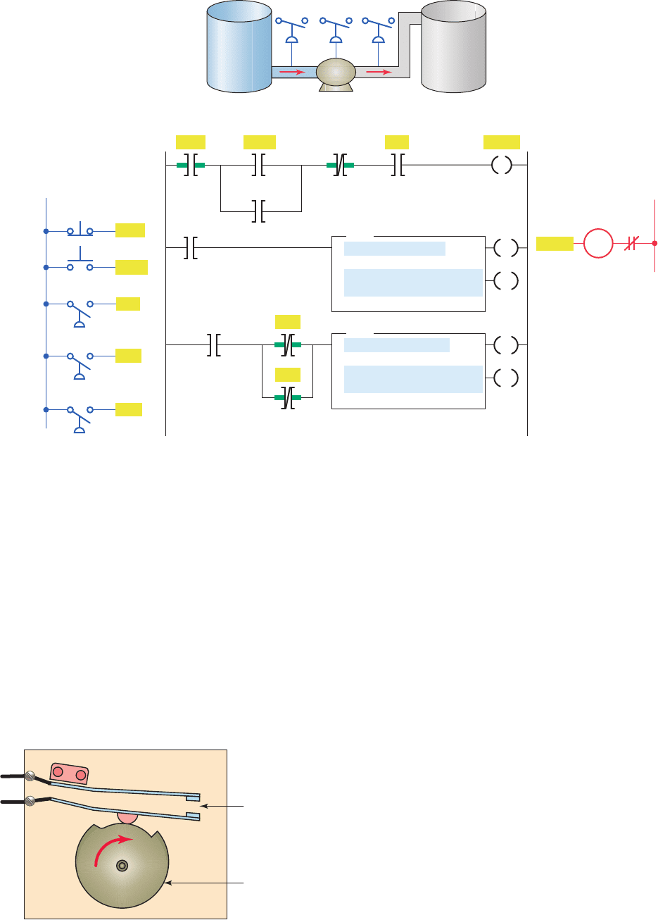
Figure 7-24 shows a program that uses both the on-
delay and the off-delay timer instruction. The process
involves pumping uid from tank A to tank B. The opera-
tion of the process can be summarized as follows:
• Before starting, PS1 must be closed.
• When the start button is pushed, the pump starts.
The button can then be released and the pump con-
tinues to operate.
• When the stop button is pushed, the pump stops.
• PS2 and PS3 must be closed 5 s after the pump
starts. If either PS2 or PS3 opens, the pump will
shut off and will not be able to start again for an-
other 14 s.
7. 5 Retentive Timer
A retentive timer accumulates time whenever the device
receives power, and it maintains the current time should
power be removed from the device. When the timer ac-
cumulates time equal to its preset value, the contacts of
the device change state. Loss of power to the timer after
reaching its preset value does not affect the state of the
contacts. The retentive timer must be intentionally reset
with a separate signal for the accumulated time to be reset
and for the contacts of the device to return to its nonener-
gized state.
Figure 7-25 illustrates the action of a motor-driven,
electromechanical retentive timer used in some appli-
ances. The shaft-mounted cam is driven by a motor. Once
power is applied, the motor starts turning the shaft and
• Instantaneous contact TD-3 closes to switch the
green light on, and instantaneous contact TD-4
opens to switch the red light off.
• After a 5-s time-delay period, timed contact TD-1
closes to energize motor starter M1, and timed con-
tact TD-2 opens to de-energize motor starter M2.
Figure7-23 shows an equivalent PLC program of the
hardwired off-delay timer relay circuit containing both in-
stantaneous and timed contacts. The timer instruction car-
ries out all of the functions of the original physical timer.
Figure 7-22 Hardwired off-delay timer relay circuit with
both instantaneous and timed contacts.
TD-4
L2
5 s
TD-1
OL
TD-2
OL
TD-3
LS1
L1
R
G
M2
M1
TD
Figure 7-23 Equivalent PLC program of the hardwired off-delay timer relay circuit
containing both instantaneous andtimed contacts.
L1
L2
LS1
Ladder logic program
M1
M2
G
R
Input Outputs
OL
OL
TOF
TIMER OFF DELAY
Timer T4:1
Time base 1.0
Preset 5
Accumulated 0
EN
DN
T4:/DN
T4:/DN
T4:/EN
T4:/EN
LS1
M1
M2
G
R
R
G
pet10882_ch07_125-148.indd 136pet10882_ch07_125-148.indd 136 7/23/10 9:35 PM7/23/10 9:35 PM
Programming Timers Chapter 7 137
on-delay timer (TON), with one major exception—a re-
tentive timer reset (RES) instruction. Unlike the TON,
the RTO will hold its accumulated value when the timer
rung goes false and will continue timing where it left off
when the timer rung goes true again. This timer must be
accompanied by a timer reset instruction to reset the ac-
cumulated value of the timer to 0. The RES instruction
is the only automatic means of resetting the accumu-
lated value of a retentive timer. The RES instruction has
the same address as the timer it is to reset. Whenever
the RES instruction is true, both the timer accumulated
value and the timer done bit (DN) are reset to 0. Fig-
ure7-26 shows a PLC program for a retentive on-delay
timer. The operation of the program can be summarized
as follows:
• The timer will start to time when time pushbutton
PB1 is closed.
• If the pushbutton is closed for 3 seconds and then
opened for 3 seconds, the timer accumulated value
will remain at 3 seconds.
• When the time pushbutton is closed again, the
timer picks up the time at 3 seconds and continues
timing.
cam. The positioning of the lobes of the cam and the gear
reduction of the motor determine the time it takes for the
motor to turn the cam far enough to activate the contacts.
If power is removed from the motor, the shaft stops but
does not reset.
A PLC retentive timer is used when you want to
retain accumulated time values through power loss
or the change in the rung state from true to false. The
PLC-programmed retentive on-delay timer (RTO) is
programmed in a manner similar to the nonretentive
Figure 7-24 Fluid pumping process.
OL
Start T4:5
Pump delay
PS1 Pump
Pump
Pump
L2
Output
M
Stop
Ladder logic program
Pump
T4:6
1.0
5
0
TON
TIMER ON DELAY
Timer
Time base
Preset
Accumulated
EN
DN
Pump time
T4:6
DN
T4:5
1.0
14
0
TOF
TIMER OFF DELAY
Timer
Time base
Preset
Accumulated
EN
DN
PS2
PS3
L1
Inputs
DN
Stop
PS1
PS2
PS3
Start
Tank
A
Tank
B
PS1 PS2 PS3
Pump
Figure 7-25 Electromechanical retentive timer.
Cam-operated
contact
Motor-driven
cam
pet10882_ch07_125-148.indd 137pet10882_ch07_125-148.indd 137 7/23/10 9:35 PM7/23/10 9:35 PM
138 Chapter 7 Programming Timers
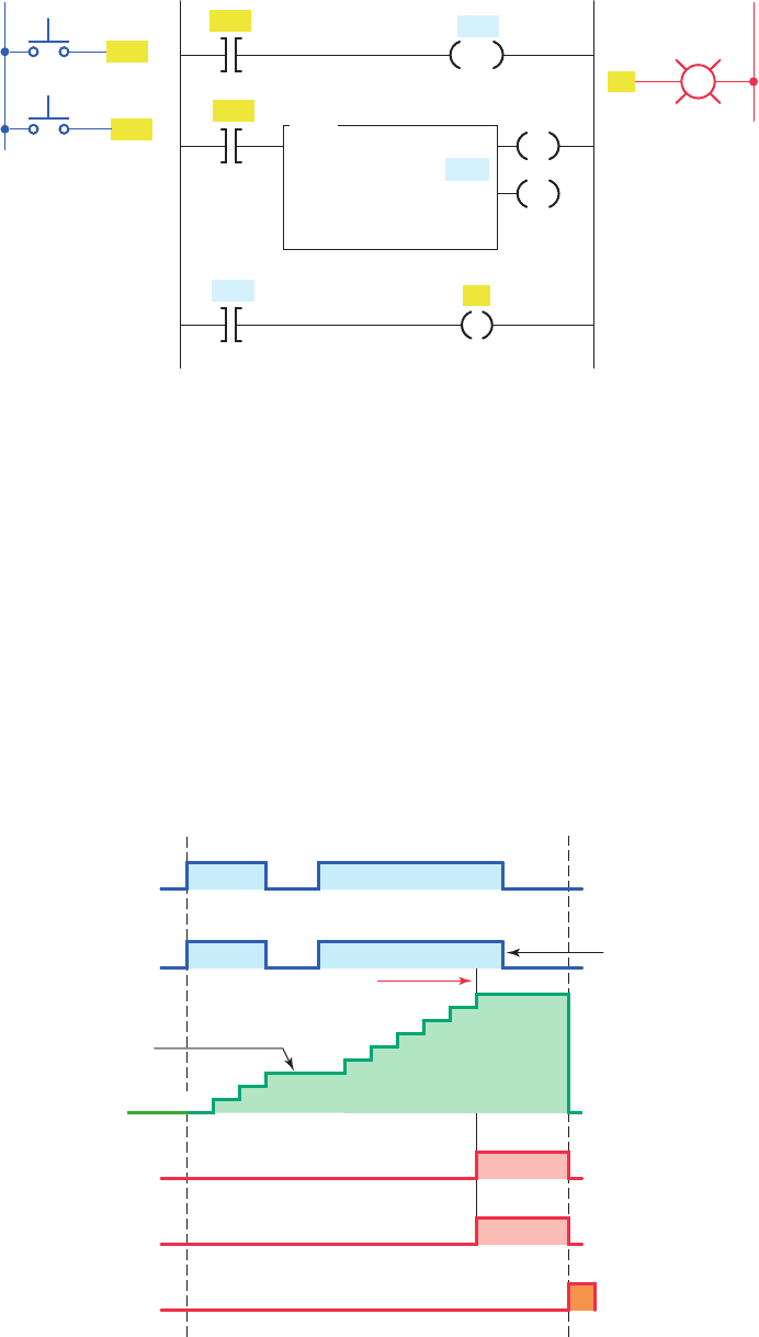
• If the timing rung goes false the timer will stop tim-
ing but will recommence timing for the stored accu-
mulated value each time the rung goes true.
• When the reset PB2 is closed, the T4:2/DN bit is
reset to 0 and turns the pilot light output off. The ac-
cumulated value is also reset and held at zero until
the reset pushbutton is opened.
The program drawn in Figure7-28 illustrates a prac-
tical application for an RTO. The purpose of the RTO
timer is to detect whenever a piping system has sustained
• When the accumulated value (9) equals the preset
value (9), the timer done bit T4:2/DN is set to 1 and
the pilot light output PL is switched on.
• Whenever the momentary reset pushbutton is closed
the timer accumulated value is reset to 0.
Figure7-27 shows a timing chart for the retentive on-
delay timer program. The timing operation can be sum-
marized as follows:
• When the timing rung is true (PB1 closed) the timer
will commence timing.
Figure 7-27 Retentive on-delay timer timing chart.
Accumulated value
retained when rung
condition goes false
Accumulated value
DN (done) bit
PL output
Reset input PB2
Enable bit is reset
when input pushbutton
PB1 is opened.
0
1
2
3
4
5
6
7
8
9
10 11 12
Time in seconds
0123456789
Tr ue
False
On
Off
On
Off
On
Off
On
Off
Accum ⴝ Preset
EN (enable) bit
Time input PB1
Figure 7-26 Retentive on-delay timer program.
PB2
PB1
L2
Output
T4:2
RES
DN
Ladder logic program
PB2
Time
PB1
L1
Inputs
Reset
RTO
RETENTIVE TIMER ON
Timer T4:2
Time Base 1.0
Preset 9
Accumulated 0
EN
DN
PL
PL
T4:2
pet10882_ch07_125-148.indd 138pet10882_ch07_125-148.indd 138 7/23/10 9:35 PM7/23/10 9:35 PM
Programming Timers Chapter 7 139
the problem has been corrected, the alarm system can be
reactivated by switching the key switch to open contact
position.
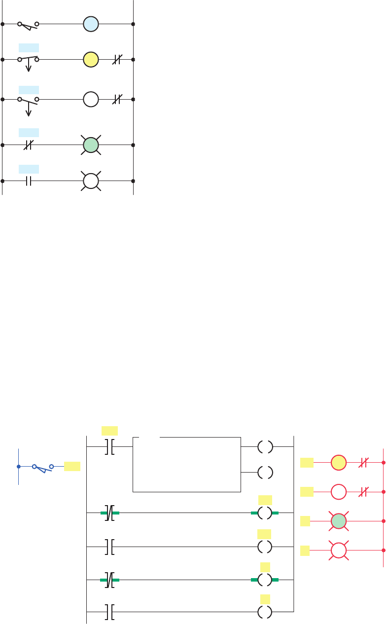
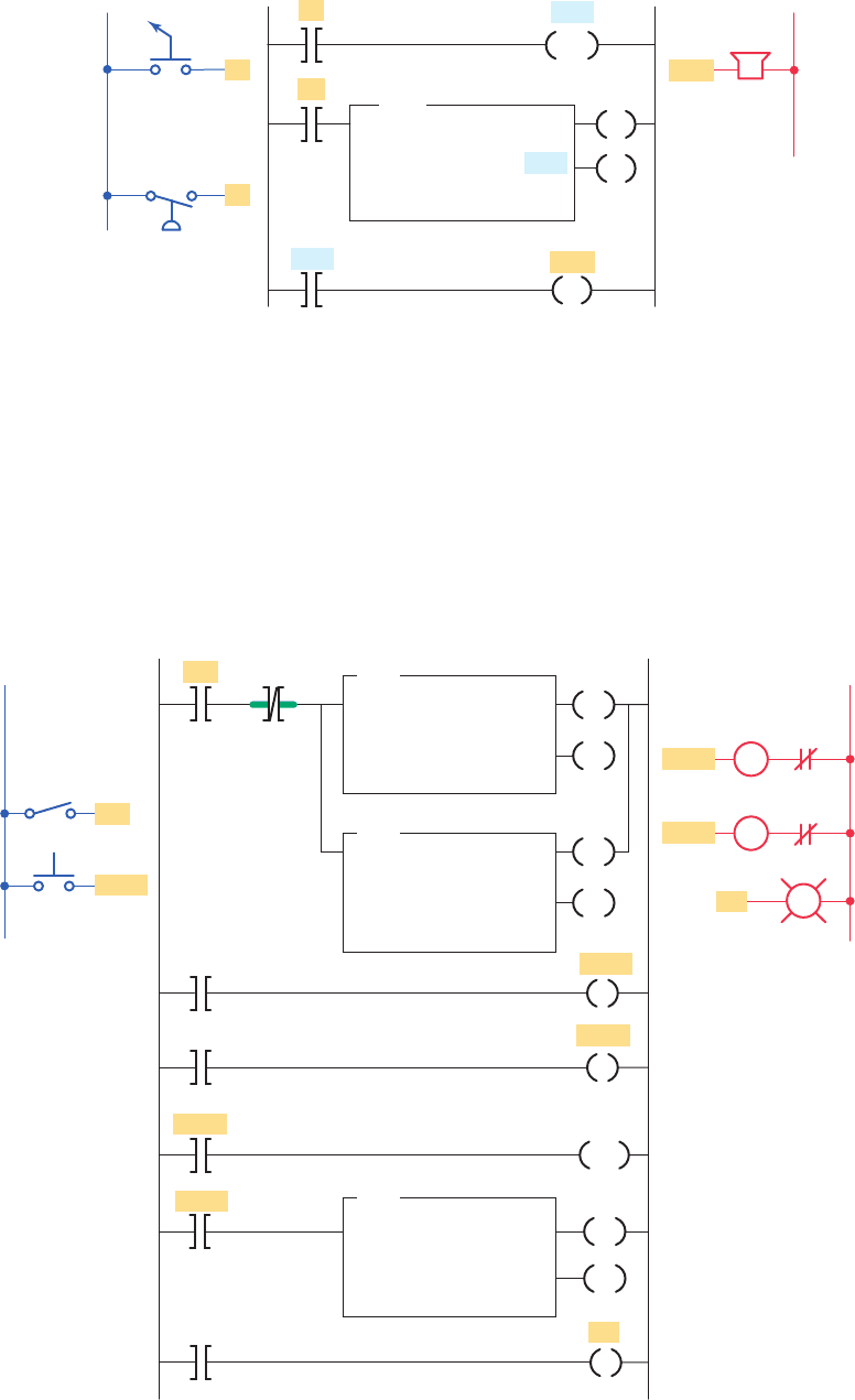
Figure 7-29 shows a practical application that
uses the on-delay, off-delay, and retentive on-delay
a cumulative overpressure condition for 60 s. At that
point, a horn is sounded automatically to call attention
to the malfunction. When they are alerted, maintenance
personnel can silence the alarm by switching the key
switch S1 to the reset (contact closed) position. After
Figure 7-28 Retentive on-delay timer alarm program.
Reset
Key switch
Pressure
switch
L1
Inputs
L2
Output
Ladder logic program
S1
S1
PS
PS
RTO
RETENTIVE TIMER ON
Timer T4:1
Preset 60
Accumulated 0
RES
EN
DN
Horn
Horn
T4:1
DN
T4:1
T4:2
L1
Inputs
Reset
Reset
SW
SW
Ladder logic program
T4:0
1.0
10
0
TON
TIMER ON DELAY
Timer
Time base
Preset
Accumulated
Pump
Pump
Pump
T4:2
1.0
10800
0
RTO
RETENTIVE TIMER ON
Timer
Time base
Preset
Accumulated
EN
DN
T4:1
DN
T4:1
1.0
15
0
TOF
TIMER OFF DELAY
Timer
Time base
Preset
Accumulated
EN
Motor
Motor
T4:0
DN
PL
OL
L2
Outputs
OL
PL
T4:2
DN
T4:2
RES
DN
Pump running time
Pump Off time dela
y
Motor starting time delay
DN
DN
EN
M2
M1
Figure 7-29 Bearing lubrication program.
pet10882_ch07_125-148.indd 139pet10882_ch07_125-148.indd 139 7/23/10 9:35 PM7/23/10 9:35 PM

140 Chapter 7 Programming Timers
• After the preset time period of 20 s, TD2-1 contact
closes to energize motor starter coil M3, and so
motor 3 starts.
Figure7-31 shows an equivalent PLC program of the
hardwired sequential time-delayed motor-starting circuit.
Two programmed on-delay timers are cascaded together
to obtain the same logic as the original hardwired timer
relay circuit. Note that the output of timer T4:1 is used to
control the input logic to timer T4:2.
Two timers can be interconnected to form an oscil-
lator circuit. The oscillator logic is basically a timing
circuit programmed to generate periodic output pulses
of any duration. Figure 7-32 shows the program for an
annunciator asher circuit. Two internal timers form the
oscillator circuit, which generates a timed, pulsed output.
The oscillator circuit output is programmed in series with
the alarm condition. If the alarm condition (temperature,
pressure, or limit switch) is true, the appropriate output
indicating light will ash. Note that any number of alarm
conditions could be programmed using the same asher
circuit.
At times you may require a time-delay period longer
than the maximum preset time allowed for the single timer
instruction of the PLC being used. When this is the case,
the problem can be solved by simply cascading timers, as
illustrated in Figure7-33 . The operation of the program
can be summarized as follows:
• The total time-delay period required is 42,000 s.
• The rst timer, T4:1, is programmed for a preset
time of 30,000 s and begins timing when input SW
is closed.
instructions in the same program. In this industrial ap-
plication, there is a machine with a large steel shaft
supported by babbitted bearings. This shaft is coupled
to a large electric motor. The bearings need lubrication,
which is supplied by an oil pump driven by a small
electric motor. The operation of the program can be
summarized as follows:
• To start the machine, the operator turns SW on.
• Before the motor shaft starts to turn, the bearings
are supplied with oil by the pump for 10 seconds.
• The bearings also receive oil when the machine is
running.
• When the operator turns SW off to stop the
machine, the oil pump continues to supply oil for
15seconds.
• A retentive timer is used to track the total running
time of the pump. When the total running time is
3 hours, the motor is shut down and a pilot light is
turned on to indicate that the lter and oil need to be
changed.
• A reset button is provided to reset the process after
the lter and oil have been changed.
Retentive timers do not have to be timed out com-
pletely to be reset. Rather, such a timer can be reset at
any time during its operation. Note that the reset input
to the timer will override the control input of the timer
even though the control input to the timer has logic
continuity.
7. 6 Cascading Timers
The programming of two or more timers together is called
cascading. Timers can be interconnected, or cascaded, to
satisfy a number of logic control functions.
Figure 7-30 shows how three motors can be started
automatically in sequence with a 20 s time delay between
each using two hardwired on-delay timers. The operation
of the circuit can be summarized as follows:
• Motor starter coil M1 is energized when the
momentary start pushbutton PB2 is actuated.
• As a result, motor 1 starts, contact M1-1 closes to
seal in M1, and timer coil TD1 is energized to begin
the rst time-delay period.
• After the preset time period of 20 s, TD1-1 contact
closes to energize motor starter coil M2.
• As a result, motor 2 starts and timer coil TD2
is energized to begin the second time-delay
period.
L2
(20 s)
L1
PB1
M1-1
TD2-1
OL
OL
TD1-1
OL
TD1
PB2
TD2
M1
M3
(20 s)
M2
Stop
Start
Figure 7-30 Hardwired sequential time-delayed motor-
starting circuit.
pet10882_ch07_125-148.indd 140pet10882_ch07_125-148.indd 140 7/23/10 9:35 PM7/23/10 9:35 PM
Programming Timers Chapter 7 141
• Once T4:2 reaches its preset time, the T4:2/DN bit
will be set to 1, which switches on the output PL,
the pilot light, to indicate the completion of the full
42,000-s time delay.
• When T4:1 completes its time-delay period 30,000 s
later, the T4:1/DN bit will be set to 1.
• This in turn activates the second timer, T4:2, which
is preset for the remaining 12,000 s of the total
42,000-s time delay.
L1 L2
PB1
PB1 PB2
PB2
Ladder logic program
Inputs Outputs
M1
M2
M3
M1
M1
OL
OL
OL
Start
Stop
EN
M1
DN
TON
TIMER ON DELAY
Timer
Preset
Accumulated
T4:1
20
0
EN
T4:1/DN
T4:1/DN
T4:2/DN
DN
T4:2
20
0
TON
TIMER ON DELAY
Timer
Preset
Accumulated
M2
M3
Figure 7-31 Equivalent PLC program of the sequential time-delayed motor-starting circuit.
L1
L2
Outputs
Inputs
T4:6
DN
Ladder logic program
T4:5
1.0
1
0
TON
TIMER ON DELAY
Timer
Time base
Preset
Accumulated
EN
G
DN
T4:5
T4:6
1.0
1
0
TON
TIMER ON DELAY
Timer
Time base
Preset
Accumulated
EN
DN
R
T4:5
Y
Y
R
G
T4:5
DN
TS1
PS1
TS1
PS1
LS1
LS1
T4:5
DN
DN
DN
Figure 7-32 Annunciator fl asher program.
pet10882_ch07_125-148.indd 141pet10882_ch07_125-148.indd 141 7/23/10 9:35 PM7/23/10 9:35 PM
142 Chapter 7 Programming Timers
• Opening input SW at any time will reset both timers
and switch output PL off.
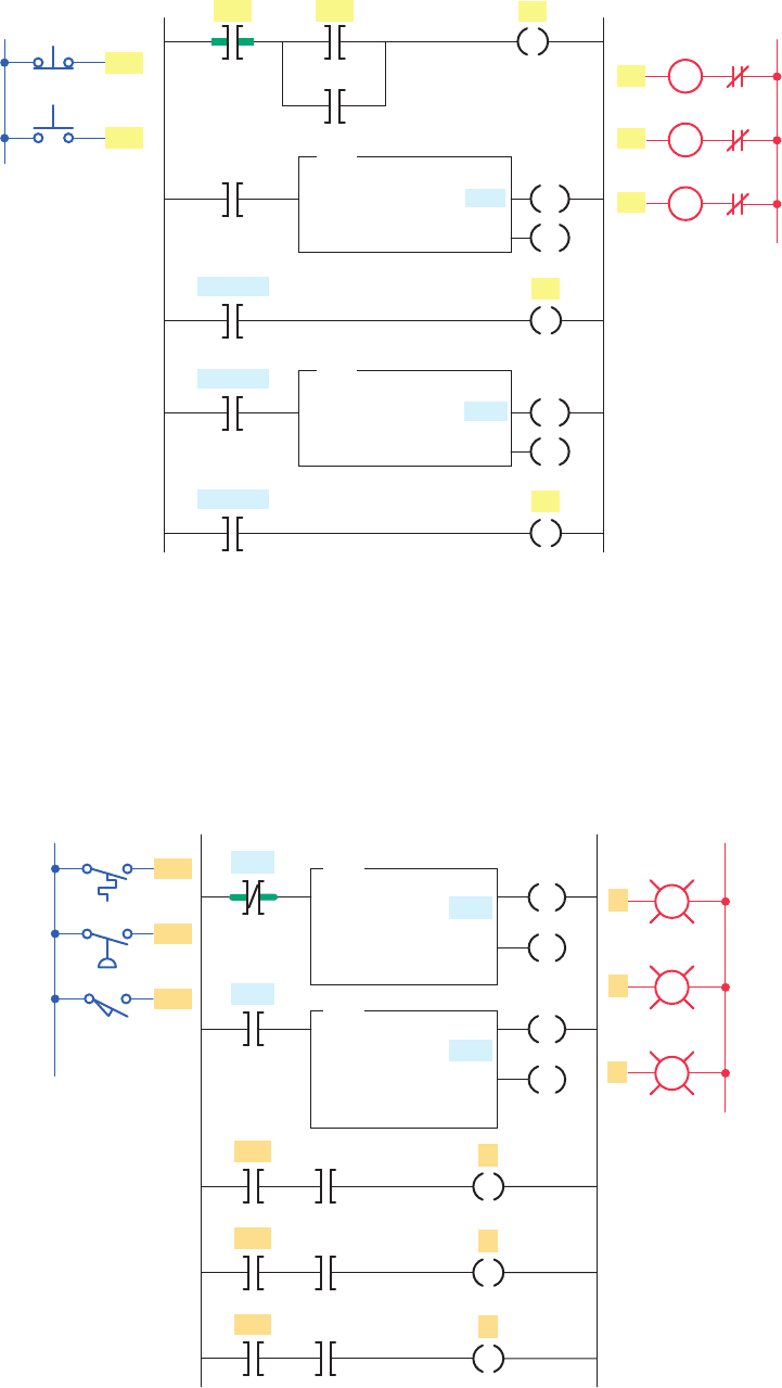
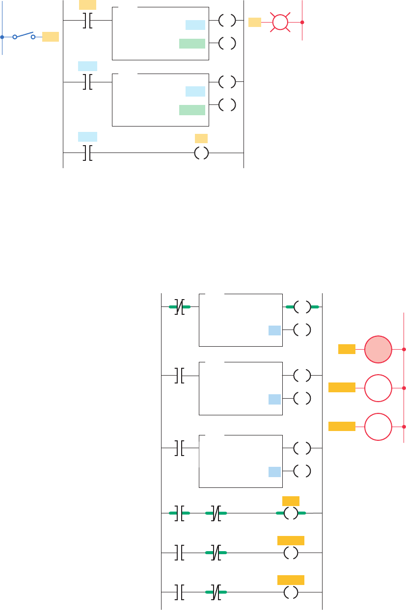
A typical application for PLC timers is the control of
traf c lights. The ladder logic circuit of Figure 7-34 il-
lustrates a control of a set of traf c lights in one direc-
tion. The operation of the program can be summarized as
follows:
• Transition from red light to green light to amber
light is accomplished by the interconnection of the
three TON timer instructions.
• The input to timer T4:0 is controlled by the T4:2
done bit.
• The input to timer T4:1 is controlled by the T4:0
done bit.
• The input rung to timer T4:2 is controlled by the
T4:1 done bit.
• The timed sequence of the lights is:
Red—30 s on
Green—25 s on
Amber—5 s on
• The sequence then repeats itself.
The chart shown in Figure 7-35 shows the timed se-
quence of the lights for two-directional control of traf c
lights.
Figure 7-36 shows the original traf c light program
modi ed to include three more lights that control traf c
ow in two directions.
Figure 7-33 Cascading of timers for longer time delays.
L2
Output
Ladder logic program
T4:1
1.0
30000
0
TON
TIMER ON DELAY
Timer
Time base
Preset
Accumulated
EN
DN
T4:2
1.0
12000
0
TON
TIMER ON DELAY
Timer
Time base
Preset
Accumulated
EN
DN
SW
T4:1
PL
DN
T4:2
DN
SW
L1
Input
PL
Figure 7-34 Control of traffi c lights in one direction.
T4:2
DN
Ladder logic program
T4:0
1.0
30
0
TON
TIMER ON DELAY
Timer
Time base
Preset
Accumulated
DN
T4:0
DN
T4:1
1.0
25
0
TON
TIMER ON DELAY
Timer
Time base
Preset
Accumulated
EN
DN
T4:1
T4:2
1.0
5
0
TON
TIMER ON DELAY
Timer
Time base
Preset
Accumulated
EN
DN
T4:0
EN
T4:0
T4:1
EN
T4:1
T4:2
EN
T4:2
L2
Outputs
Red
Red
Green
Amber
Red
Traffic lights
Red time
Green time
Amber time
EN
Green
Green
Amber
Amber
DN
DN
DN
DN
pet10882_ch07_125-148.indd 142pet10882_ch07_125-148.indd 142 7/23/10 9:35 PM7/23/10 9:35 PM