Petruzella F.D. Programmable Logic Controllers
Подождите немного. Документ загружается.

Developing Fundamental PLC Wiring Diagrams and Ladder Logic Programs Chapter 6 103
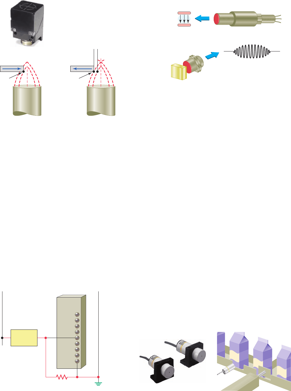
Figure 6-21 Proximity sensor sensing range.
Source: Photo courtesy Eaton Corporation, www.eaton.com.
Hysteresis
zone
Cube sensor
with status LED
Target
Operating
point
Release
point
Figure 6-22 Bleeder resistor connected to continuously
power a proximity sensor.
Proximity
sensor
L1 L2
Input
module
Bleeder
resistor
sensor turns on, it will remain on until the target moves to
the release point. Hysteresis is needed to keep proximity
sensors from chattering when subjected to shock and vi-
bration, slow-moving targets, or minor disturbances such
as electrical noise and temperature drift. Most proximity
sensors come equipped with an LED status indicator to
verify the output switching action.
As a result of solid-state switching of the output, a
small leakage current ows through the sensor even
when the output is turned off. Similarly, when the sensor
is on, a small voltage drop is lost across its output termi-
nals. To operate properly, a proximity sensor should be
powered continuously. Figure 6-22 illustrates the use of
a bleeder resistor connected to allow enough current for
the sensor to operate but not enough to turn on the input
of the PLC.
Capacitive proximity sensors are similar to inductive
proximity sensors. The main differences between the
two types are that capacitive proximity sensors produce
an electrostatic eld instead of an electromagnetic eld
and are actuated by both conductive and nonconductive
materials.
Figure 6-23 illustrates the operation of a capacitive
sensor. A capacitive sensor contains a high-frequency
oscillator along with a sensing surface formed by two
metal electrodes. When the target nears the sensing sur-
face, it enters the electrostatic eld of the electrodes and
changes the capacitance of the oscillator. As a result, the
oscillator circuit begins oscillating and changes the out-
put state of the sensor when it reaches certain amplitude.
As the target moves away from the sensor, the oscilla-
tor’s amplitude decreases, switching the sensor back to
its original state.
Capacitive proximity sensors will sense metal objects
as well as nonmetallic materials such as paper, glass, liq-
uids, and cloth. They typically have a short sensing range
of about 1 inch, regardless of the type of material being
sensed. The larger the dielectric constant of a target, the
easier it is for the capacitive sensor to detect. This makes
possible the detection of materials inside nonmetallic
containers as illustrated in Figure 6-24 . In this example,
the liquid has a much higher dielectric constant than the
cardboard container, which gives the sensor the ability to
Figure 6-23 Capacitive proximity sensor.
Sensor
electrodes
Electrostatic
field
Oscillator waveform
Target
present
Target
absent
Target
absent
Metallic or
nonmetallic
target
MILK
MILK
MILK
Figure 6-24 Capacitive proximity sensor liquid detection.
Source: Photo courtesy Omron Industrial Automation, www.ia.omron.com.
pet10882_ch06_095-124.indd 103pet10882_ch06_095-124.indd 103 7/23/10 9:22 PM7/23/10 9:22 PM
104 Chapter 6 Developing Fundamental PLC Wiring Diagrams and Ladder Logic Programs
see through the container and detect the liquid. In the pro-
cess shown, detected empty containers are automatically
diverted via the push rod.
Inductive proximity switches may be actuated only by
a metal and are insensitive to humidity, dust, dirt, and the
like. Capacitive proximity switches, however, can be ac-
tuated by any dirt in their environment. For general appli-
cations, the capacitive proximity switches are not really
an alternative but a supplement to the inductive proximity
switches. They are a supplement when there is no metal
available for the actuation (e.g., for woodworking ma-
chines and for determining the exact level of liquids or
powders).
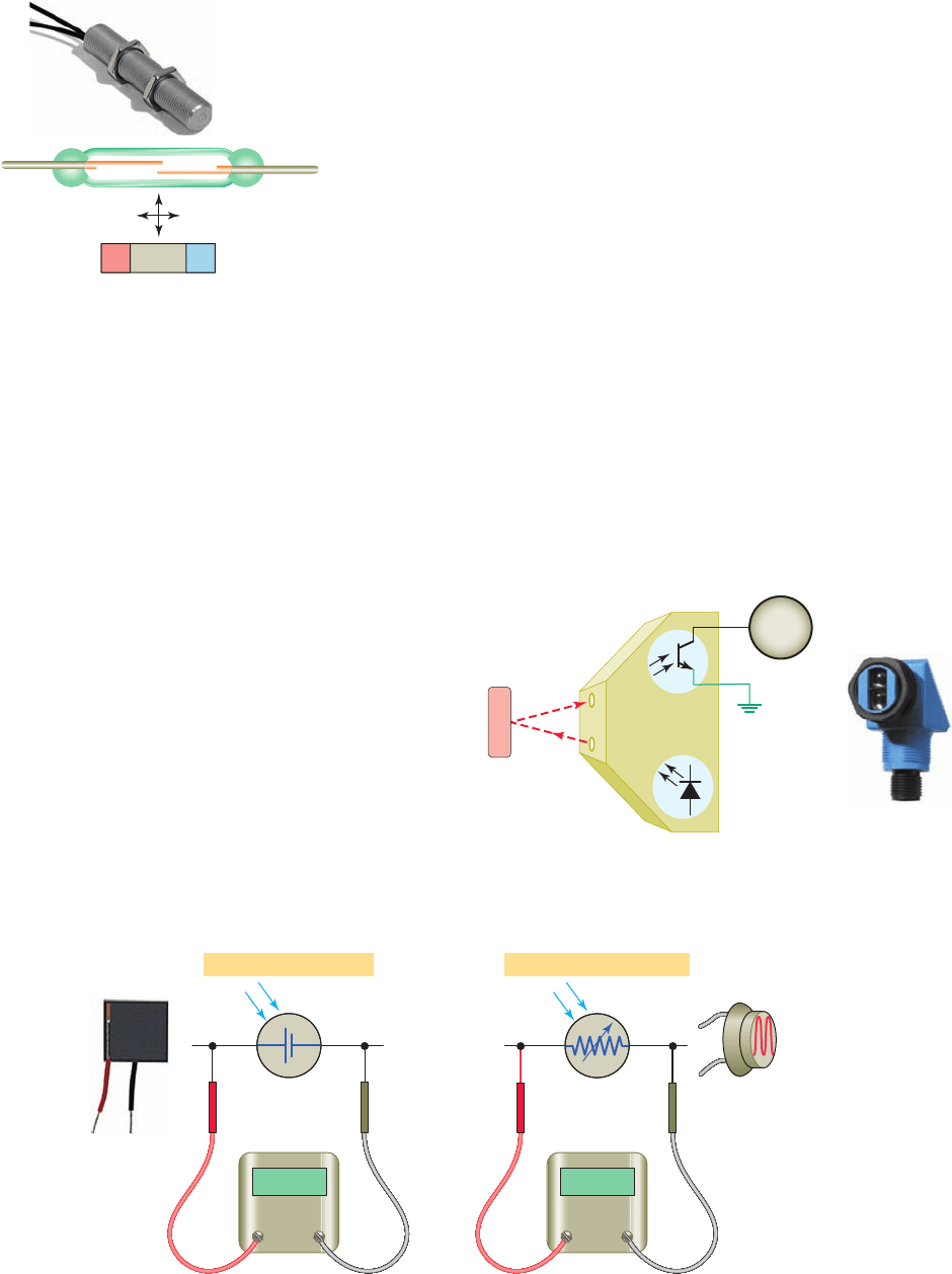
Magnetic Reed Switch
A ma
gnetic reed switch is composed of two at contact
tabs that are hermetically sealed (airtight) in a glass tube
lled with protective gas, as illustrated in Figure 6-25 .
When a magnetic force is generated parallel to the reed
switch, the reeds become ux carriers in the magnetic cir-
cuit. The overlapping ends of the reeds become opposite
Figure 6-25 Magnetic reed switch.
Source: Courtesy of Reed Switch Developments Corp., used with permission.
Reed switch sensor
NS
Figure 6-26 Photovoltaic and photoconductive light cells.
ⴙ ⴚ
DCV
(a) Photovoltaic solar cell (b) Photoconductive cell
Light changes resistanceLight produces voltage
Ohms
magnetic poles, which attract each other. If the magnetic
force between the poles is strong enough to overcome
the restoring force of the reeds, the reeds will be drawn
together to actuate the switch. Because the contacts are
sealed, they are unaffected by dust, humidity, and fumes;
thus, their life expectancy is quite high.
Light Sensors
The photovoltaic cell and the photoconductive cell,
illustrated in
Figure 6-26 , are two examples of light
sensors. The photovoltaic or solar cell reacts to light
by converting the light energy directly into electric en-
ergy. The photoconductive cell (also called a photore-
sistive cell ) reacts to light by change in the resistance
of the cell.
A photoelectric sensor is an optical control device
that operates by detecting a visible or invisible beam of
light and responding to a change in the received light in-
tensity. Photoelectric sensors are composed of two basic
components: a transmitter (light source) and a receiver
(sensor), as shown in Figure 6-27 . These two compo-
nents may or may not be housed in separate units. The
Figure 6-27 Photoelectric sensor.
Source: Photo courtesy SICK, Inc., www.sick.com.
Modulated
light
beam
Load
Transmitter
Receiver
Object to
be sensed
pet10882_ch06_095-124.indd 104pet10882_ch06_095-124.indd 104 7/23/10 9:22 PM7/23/10 9:22 PM
Developing Fundamental PLC Wiring Diagrams and Ladder Logic Programs Chapter 6 105
Figure 6-28 Through-beam scan.
Source: Photo courtesy SICK, Inc., www.sick.com.
Transmitter
Receiver
basic operation of a photoelectric sensor can be sum-
marized as follows:
• The transmitter contains a light source, usually an
LED along with an oscillator.
• The oscillator modulates or turns the LED on and
off at a high rate of speed.
• The transmitter sends this modulated light beam to
the receiver.
• The receiver decodes the light beam and switches
the output device, which interfaces with the load.
• The receiver is tuned to its emitter’s modulation
frequency and will only amplify the light signal that
pulses at the speci c frequency.
• Most sensors allow adjustment of how much light
will cause the output of the sensor to change state.
• Response time is related to the frequency of the
light pulses. Response times may become impor-
tant when an application calls for the detection of
very small objects, objects moving at a high rate of
speed, or both.
The scan technique refers to the method used by pho-
toelectric sensors to detect an object. The through-beam
scan technique (also called direct scan) places the trans-
mitter and receiver in direct line with each other, as il-
lustrated in Figure 6-28 . Because the light beam travels
in only one direction, through-beam scanning provides
long-range sensing. Quite often, a garage door opener has
a through-beam photoelectric sensor mounted near the
oor, across the width of the door. For this application
thesensor senses that nothing is in the path of the door
when it is closing.
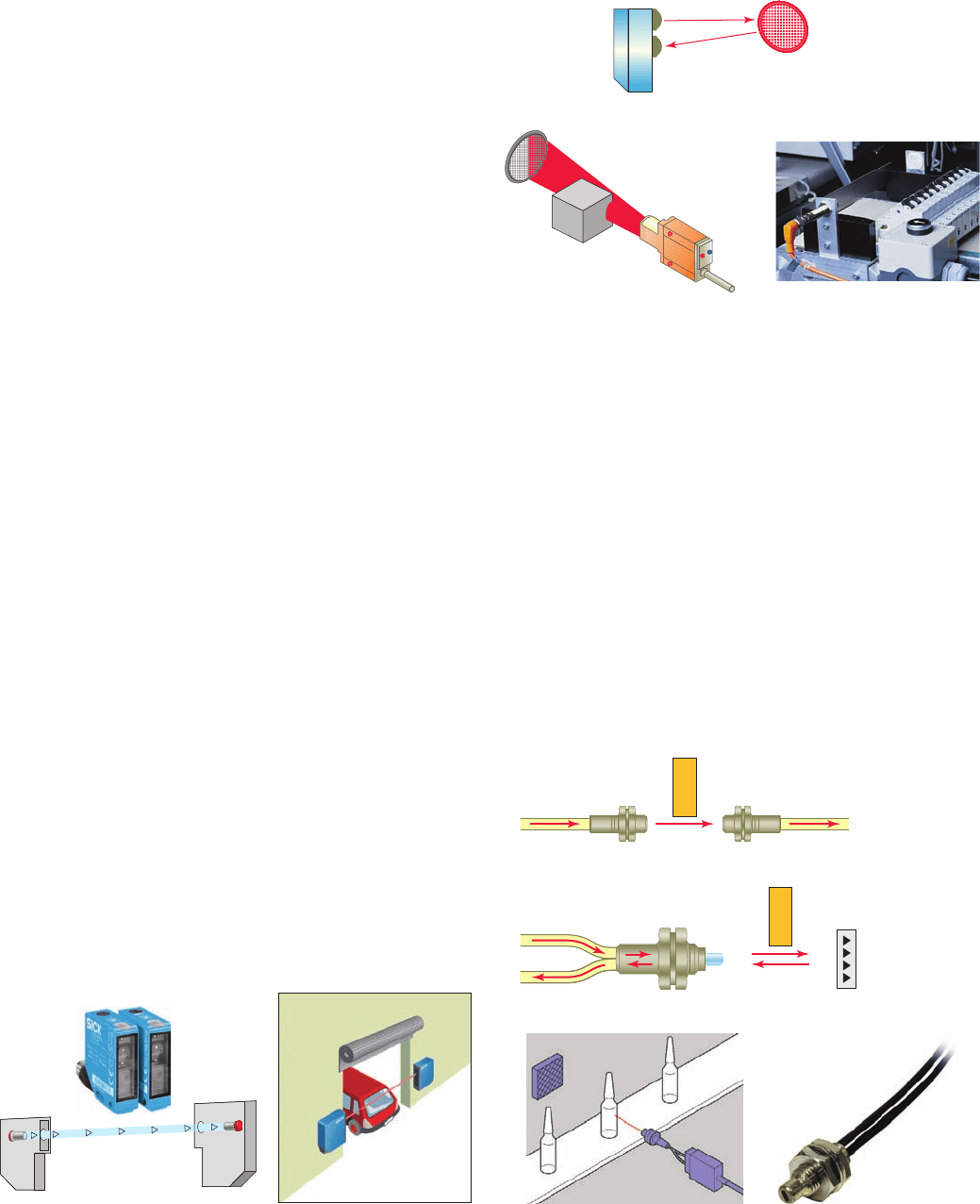
In a retrore ective scan, the transmitter and receiver
are housed in the same enclosure. This arrangement re-
quires the use of a separate re ector or re ective tape
mounted across from the sensor to return light back to
the receiver. The retrore ective scan is designed to re-
spond to objects that interrupt the beam normally main-
tained between the transmitter and receiver, as illustrated
Figure 6-29 Retrorefl ective scan.
Source: Photo courtesy ifm efector, www.ifm.com/us.
Reflector
Transmitter
Receiver
Figure 6-30 Fiber optic sensors.
Source: Photo courtesy Omron Industrial Automation, www.ia.omron.com.
Through-beam
To receiver
To receiver
From transmitter
From transmitter
Retroreflective
in Figure 6-29 . In contrast to a through-beam applica-
tion, retrore ective sensors are used for medium-range
applications.
Fiber optics is not a scan technique, but another method
for transmitting light. Fiber optic sensors use a exible
cable containing tiny bers that channel light from emitter
to receiver, as illustrated in Figure 6-30 . Fiber optic sensor
systems are completely immune to all forms of electrical
interference. The fact that an optical ber does not contain
any moving parts and carries only light means that there is
no possibility of a spark. This means that it can be safely
used even in the most hazardous sensing environments
such as a re nery for producing gases, grain bins, mining,
pharmaceutical manufacturing, and chemical processing.
pet10882_ch06_095-124.indd 105pet10882_ch06_095-124.indd 105 7/23/10 9:22 PM7/23/10 9:22 PM
106 Chapter 6 Developing Fundamental PLC Wiring Diagrams and Ladder Logic Programs
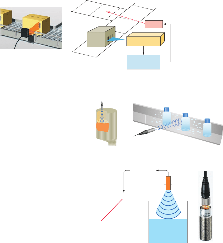
Bar code technology is widely implemented in in-
dustry to enter data quickly and accurately. Bar code
scanners are the eyes of the data collection system. A
light source within the scanner illuminates the bar code
symbol; those bars absorb light, and spaces re ect light.
A photodetector collects this light in the form of an
electronic-signal pattern representing the printed sym-
bol. The decoder receives the signal from the scanner
and converts these data into the character data represen-
tation of the symbol’s code. Figure 6-31 illustrates a typ-
ical PLC application which involves a bar code module
reading the bar code on boxes as they move along a con-
veyor line. The PLC is then used to divert the boxes to
the appropriate product lines according to the data read
from the bar code.
Ultrasonic Sensors
An ultr
asonic sensor operates by sending high-frequency
sound waves toward the target and measuring the time it
takes for the pulses to bounce back. The time taken for
this echo to return to the sensor is directly proportional to
the distance or height of the object because sound has a
constant velocity.
Figure 6-32 illustrates a practical application in which
the returning echo signal is electronically converted to a
4- to 20-mA output, which supplies a monitored ow rate
to external control devices. The operation of this process
can be summarized as follows:
• The 4-20 mA represents the sensor’s measurement
span.
• The 4-mA set point is typically placed near the bot-
tom of the empty tank, or the greatest measurement
distance from the sensor.
• The 20-mA set point is typically placed near the top
of the full tank, or the shortest measurement dis-
tance from the sensor.
• The sensor will proportionately generate a 4-mA
signal when the tank is empty and a 20-mA signal
when the tank is full.
• Ultrasonic sensors can detect solids, uids, granular
objects, and textiles. In addition, they enable the de-
tection of different objects irrespective of color and
transparency and therefore are ideal for monitoring
transparent objects.
Strain/Weight Sensors
A str
ain gauge converts a mechanical strain into an elec-
tric signal. Strain gauges are based on the principle that
Figure 6-31 PLC bar code application.
Source: Courtesy Keyence Canada, Inc.
Programmable
controller
Scanner/decoder
Diverter
Figure 6-32 Ultrasonic sensor.
Source: Courtesy Keyence Canada, Inc.
Detecting transparent bottlesDetecting the level
of chocolate
4
5
5
10
15
20
25
30
30
20
Level detection
Output
(mA)
Inches
Inches
4- to 20-mA
output
pet10882_ch06_095-124.indd 106pet10882_ch06_095-124.indd 106 7/23/10 9:22 PM7/23/10 9:22 PM
Developing Fundamental PLC Wiring Diagrams and Ladder Logic Programs Chapter 6 107
the resistance of a conductor varies with length and cross-
sectional area. The force applied to the gauge causes the
gauge to bend. This bending action also distorts the physical
size of the gauge, which in turn changes its resistance. This
resistance change is fed to a bridge circuit that detects small
changes in the gauge’s resistance. Strain gauge load cells
are usually made with steel and sensitive strain gauges. As
the load cell is loaded, the metal elongates or compresses
very slightly. The strain gauge detects this movement and
translates it to a varying voltage signal. Many sizes and
shapes of load cells are available, and they range in sensitiv-
ity from grams to millions of pounds. Strain gauge–based
load cells are used extensively for industrial weighing ap-
plications similar to the one illustrated in Figure 6-33 .
Temperature Sensors
The thermocouple is the most widely used temperature
sensor
. Thermocouples operate on the principle that when
two dissimilar metals are joined, a predictable DC volt-
age will be generated that relates to the difference in tem-
perature between the hot junction and the cold junction
( Figure 6-34 ). The hot junction (measuring junction) is
the joined end of a thermocouple that is exposed to the
process where the temperature measurement is desired.
The cold junction (reference junction) is the end of a ther-
mocouple that is kept at a constant temperature to provide
a reference point. For example, a K-type thermocouple,
when heated to a temperature of 300°C at the hot junc-
tion, will produce 12.2 mV at the cold junction. Because
of their ruggedness and wide temperature range, thermo-
couples are used in industry to monitor and control oven
and furnace temperatures.
Flow Measurement
Many industrial processes depend on accurate measure-
ment of uid
ow. Although there are several ways to
measure uid ow, the usual approach is to convert the
kinetic energy that the uid has into some other measur-
able form.
Turbine -type owmeters are a popular means of mea-
surement and control of liquid products in industrial,
chemical, and petroleum operations. Turbine owme-
ters, like windmills, utilize their angular velocity (rota-
tion speed) to indicate the ow velocity. The operation
of a turbine owmeter is illustrated in Figure 6-35 . Its
basic construction consists of a bladed turbine rotor in-
stalled in a ow tube. The bladed rotor rotates on its axis
in proportion to the rate of the liquid ow through the
tube. A magnetic pickup sensor is positioned as close
to the rotor as practical. Fluid passing through the ow
tube causes the rotor to rotate, which generates pulses
in the pickup coil. The frequency of the pulses is then
transmitted to readout electronics and displayed as gal-
lons per minute.
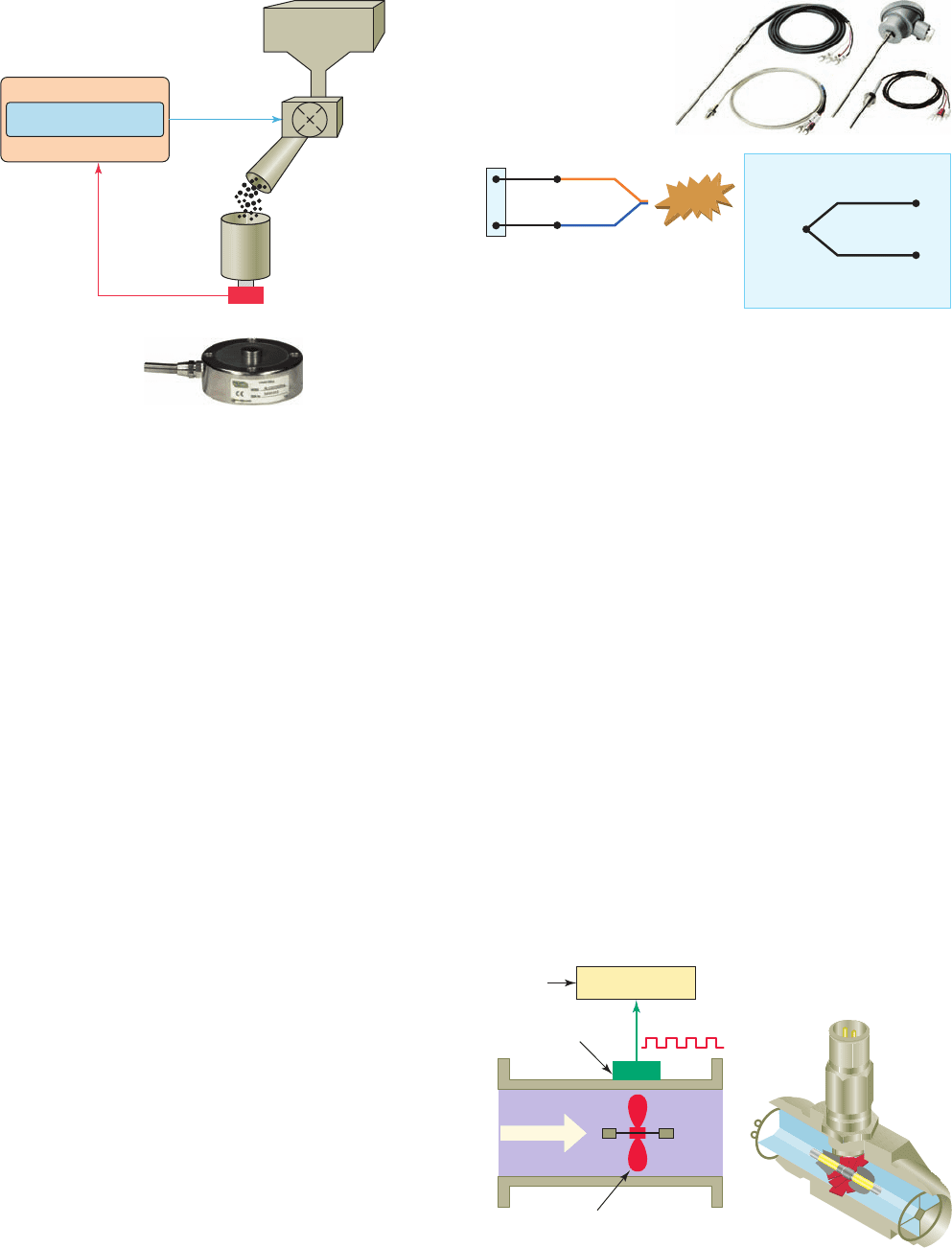
Programmable controller
Hopper
ON/OFF
control
Drum
Load cell
PLC sensor
input
560 lbs.
Figure 6-33 Strain gauge load cell.
Source: Courtesy RDP Group.
Figure 6-34 Thermocouple temperature sensor.
Source: Photo courtesy Omron Industrial Automation, www.ia.omron.com.
Chromel
(nickel-chromium)
⫹
⫺
12.2 mV
300⬚C
Alumel (nickel-aluminum)
type K thermocouple
Metal A
Metal B
Cold
j
unction
Hot
junction
HEAT
Leads
Figure 6-35 Turbine type fl owmeter.
Gallons/minute
Generated pulses
Readout
electronics
Magnetic pickup
Flow
Rotating
turbine
pet10882_ch06_095-124.indd 107pet10882_ch06_095-124.indd 107 7/23/10 9:22 PM7/23/10 9:22 PM
108 Chapter 6 Developing Fundamental PLC Wiring Diagrams and Ladder Logic Programs
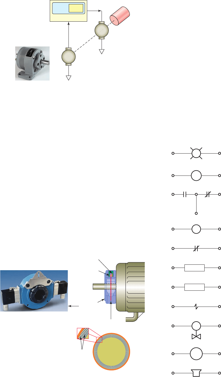
Velocity and Position Sensors
Tachometer generators
provide a convenient means of
converting rotational speed into an analog voltage sig-
nal that can be used for motor speed indication and con-
trol applications. A tachometer generator is a small AC
or DC generator that develops an output voltage (pro-
portional to its rpm) whose phase or polarity depends
on the rotor’s direction of rotation. The DC tachometer
generator usually has permanent magnetic eld excita-
tion. The AC tachometer generator eld is excited by
a constant AC supply. In either case, the rotor of the
tachometer is mechanically connected, directly or indi-
rectly, to the load.
Figure 6-36 illustrates motor speed control applications
in which a tachometer generator is used to provide a feed-
back voltage to the motor controller that is proportional to
motor speed. The control motor and tachometer generator
may be contained in the same or separate housings.
Figure 6-36 Tachometer generator feedback.
Source: Courtesy ATC Digitec.
Load
Tach
Motor
1450 rpm
CONTROLLER
Separate
tachometer
generator
Figure 6-37 Optical encoder.
Source: Photo courtesy Avtron, www.avtron.com.
Optical
encoder
Optical
sensor
Light
source
Optical
disk
Lines
An encoder is used to convert linear or rotary motion
into a binary digital signal. Encoders are used in appli-
cations where positions have to be precisely determined.
The optical encoder illustrated in Figure 6-37 uses a light
source shining on an optical disk with lines or slots that
interrupt the beam of light to an optical sensor. An elec-
tronic circuit counts the interruptions of the beam and
generates the encoder’s digital output pulses.
6.7 Output Control Devices
A variety of output control devices can be operated
by the PLC output to control traditional industrial
processes. These devices include pilot lights, control
relays, motor starters, alarms, heaters, solenoids, sole-
noid valves, small motors, and horns. Similar electri-
cal symbols are used to represent these devices both on
relay schematics and PLC output connection diagrams.
Figure 6-38 shows common electrical symbols used
Figure 6-38 Symbols for output control devices.
Pilot light
Relay
Motor starter coil
Motor overload relay contact
Heater
Solenoid
Solenoid valve
Motor
Horn
Alarm
CR1-1 CR1-2
NO NC
OL
ALARM
PL
M
SV
CR1
MTR
HTR
SOL
pet10882_ch06_095-124.indd 108pet10882_ch06_095-124.indd 108 7/23/10 9:22 PM7/23/10 9:22 PM
Developing Fundamental PLC Wiring Diagrams and Ladder Logic Programs Chapter 6 109
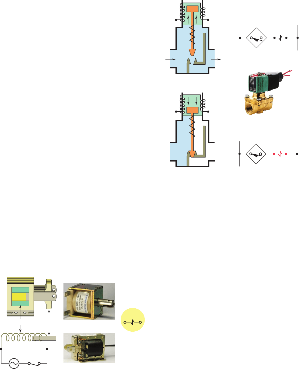
Figure 6-39 Solenoid construction and operation.
Source: Photos courtesy Guardian Electric, www.guardian-electric.com.
Air
Frame
Coil
Plunger
Symbol
DC solenoid
AC solenoid
Figure 6-40 Solenoid valve construction and operation.
Source: Photo courtesy ASCO Valve Inc., www.ascovalve.com.
L1 L2Control circuit
Solenoid coil
energized
L1 L2Control circuit
Solenoid coil
de-energized
Valve orifice opened
OutletInlet
Coil
de-energized
Valve orifice closed
Coil
energized
Valve
Solenoid operator
Figure 6-40 illustrates the construction and principle
of operation of a typical uid solenoid valve. Its operation
can be summarized as follows:
• The valve body contains an ori ce in which a disk
or plug is positioned to restrict or allow ow.
• Flow through the ori ce is either restricted or al-
lowed depending on whether the solenoid coil is
energized or de-energized.
• When the coil is energized, the core is drawn into
the solenoid coil to open the valve.
• The spring returns the valve to its original closed
position when the current coil is de-energized.
• A valve must be installed with direction of ow in
accordance with the arrow cast on the side of the
valve body.
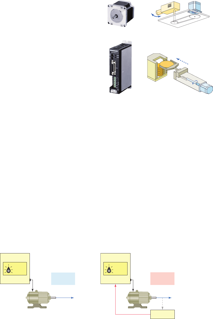
Stepper motors operate differently than standard types,
which rotate continuously when voltage is applied to their
terminals. The shaft of a stepper motor rotates in discrete
increments when electrical command pulses are applied
to it in the proper sequence. Every revolution is divided
into a number of steps, and the motor must be sent a volt-
age pulse for each step. The amount of rotation is directly
for various output devices. Although these symbols are
generally acceptable, some differences among manu-
facturers do exist.
An actuator, in the electrical sense, is any device
that converts an electrical signal into mechanical move-
ment. An electromechanical solenoid is an actuator that
uses electrical energy to magnetically cause mechani-
cal control action. A solenoid consists of a coil, frame,
and plunger (or armature, as it is sometimes called).
Figure 6-39 shows the basic construction and opera-
tion of a solenoid. Its operation can be summarized as
follows:
• The coil and frame form the xed part.
• When the coil is energized, it produces a magnetic
eld that attracts the plunger, pulling it into the
frame and thus creating mechanical motion.
• When the coil is de-energized the plunger returns
to its normal position through gravity or assistance
from spring assemblies within the solenoid.
• The frame and plunger of an AC-operated solenoid
are constructed with laminated pieces instead of a
solid piece of iron to limit eddy currents induced by
the magnetic eld.
Solenoid valves are electromechanical devices that
work by passing an electrical current through a solenoid,
thereby changing the state of the valve. Normally, there is
a mechanical element, which is often a spring, that holds
the valve in its default position. A solenoid valve is a com-
bination of a solenoid coil operator and valve, which con-
trols the ow of liquids, gases, steam, and other media.
When electrically energized, they open, shut off, or direct
the ow of media.
pet10882_ch06_095-124.indd 109pet10882_ch06_095-124.indd 109 7/23/10 9:22 PM7/23/10 9:22 PM
110 Chapter 6 Developing Fundamental PLC Wiring Diagrams and Ladder Logic Programs
proportional to the number of pulses, and the speed of
rotation is relative to the frequency of those pulses. A
1-degree-per-step motor will require 360 pulses to move
through one revolution; the degrees per step are known as
the resolution. When stopped, a stepper motor inherently
holds its position. Stepper systems are used most often
in “open-loop” control systems, where the controller tells
the motor only how many steps to move and how fast to
move, but does not have any way of knowing what posi-
tion the motor is at.
The movement created by each pulse is precise
and repeatable, which is why stepper motors are so
effective for load-positioning applications. Conver-
sion of rotary to linear motion inside a linear actua-
tor is accomplished through a threaded nut and lead
screw. Generally, stepper motors produce less than 1 hp
and are therefore frequently used in low-power posi-
tion control applications. Figure6-41 shows a stepper
motor/drive unit along with typical rotary and linear
applications.
All servo motors operate in closed-loop mode,
whereas most stepper motors operate in open-loop
mode. Closed-loop and open-loop control schemes are
illustrated in Figure 6-42 . Open loop is control with-
out feedback, for example, when the controller tells the
stepper motor how many steps to move and how fast to
move, but does not verify where the motor is. Closed-
loop control compares speed or position feedback with
the commanded speed or position and generates a modi-
ed command to make the error smaller. The error is the
difference between the required speed or position and
the actual speed or position.
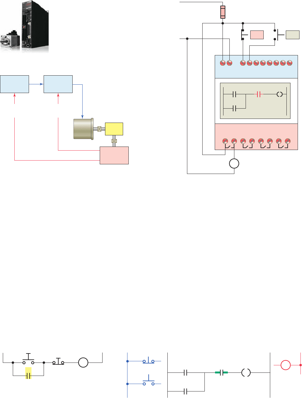
Figure 6-43 illustrates a closed-loop servo motor sys-
tem. The motor controller directs operation of the servo
motor by sending speed or position command signals to
the ampli er, which drives the servo motor. A feedback
device such as an encoder for position and a tachometer
for speed are either incorporated within the servo motor
or are remotely mounted, often on the load itself. These
provide the servo motor’s position and speed feedback
information that the controller compares to its pro-
grammed motion pro le and uses to alter its position
or speed.
6.8 Seal-In Circuits
Seal-in, or holding, circuits are very common in both
relay logic and PLC logic. Essentially, a seal-in circuit is
a method of maintaining current ow after a momentary
switch has been pressed and released. In these types of
circuits, the seal-in contact is usually in parallel with the
momentary device.
Rotary application
Linear application
Stepper motor
Motor drive
Figure 6-41 Stepper motor/drive unit.
Source: Photos courtesy Oriental Motor, www.orientalmotor.com.
Figure 6-42 Open- and closed-loop motor control systems.
Output
shaft
To load
Open-loop
control
Motor
CONTROLLER
Speed
setting
Motor
CONTROLLER
Output
shaft
To load
Closed-loop
control
Tachometer
Feedback signal
Speed
setting
pet10882_ch06_095-124.indd 110pet10882_ch06_095-124.indd 110 7/23/10 9:22 PM7/23/10 9:22 PM
Developing Fundamental PLC Wiring Diagrams and Ladder Logic Programs Chapter 6 111
Motor/controller
Controller
Servo
amplifier
Feedback
device
Tachometer: speed
Encoder: position
Load
Position
feedback
Speed
feedback
Servo
motor
Figure 6-43 Closed-loop servo motor system.
Source: Photos courtesy Omron Industrial Automation, www.ia.omron.com.
Figure 6-44 Hardwired and programmed seal-in circuit.
Programmed
Motor
starter
coil
M
Start Stop
L1L1
Inputs
L2L2
Ladder logic program Output
Hardwired
M
Motor
starter coil
M
Seal-in contact
Start
Stop
M
Motor
starter coil
Stop
Start
Figure 6-45 Motor seal-in circuit implemented using an
Allen-Bradley Pico controller.
M
Motor
starter coil
Q1
Q1
Q1
L1
L1
L2
L2
I1 I2
I2 I1
Q2 Q3
Outputs
Inputs
Q3
Stop Start
The motor stop/start circuit shown in Figure 6-44 is a
typical example of a seal-in circuit. The hardwired circuit
consists of a normally closed stop button in series with a
normally open start button. The seal-in auxiliary contact
of the starter is connected in parallel with the start button
to keep the starter coil energized when the start button is
released. When this circuit is programmed into a PLC,
both the start and stop buttons are examined for a closed
condition because both buttons must be closed to cause
the motor starter to operate.
Figure 6-45 shows a PLC wiring diagram of the motor
seal-in circuit implemented using an Allen-Bradley Pico
controller. The controller is programmed using ladder
logic. Each programming element can be entered directly
via the Pico display. This controller also lets you program
the circuit from a personal computer using PicoSoft pro-
gramming software.
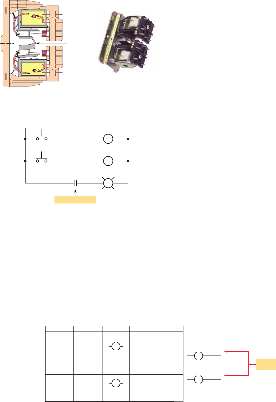
6.9 Latching Relays
Electromagnetic latching relays are designed to hold the
relay closed after power has been removed from the coil.
Latching relays are used where it is necessary for contacts
to stay open and/or closed even though the coil is ener-
gized only momentarily. Figure 6-46 shows a latching
relay that uses two coils. The latch coil is momentarily
energized to set the latch and hold the relay in the latched
position. The unlatch or release coil is momentarily
pet10882_ch06_095-124.indd 111pet10882_ch06_095-124.indd 111 7/23/10 9:22 PM7/23/10 9:22 PM
112 Chapter 6 Developing Fundamental PLC Wiring Diagrams and Ladder Logic Programs
OFF
ON
Latch coil
Unlatch coil
LL
In unlatch position
Relay contact
21
PL
L
U
Figure 6-47 Hardwired control circuit for an
electromagnetic latching relay.
Command Name Symbol Description
OTL
OTU Output
unlatch
Output latch
OTL
sets the bit to
"1" when the rung
becomes true and
retains its state when
the rung loses
continuity or a power
cycle occurs.
OTU resets the bit to
"0" when the rung
becomes true and
retains it.
Latch coil
Unlatch coil
XXX
XXX
L
Same
address
U
U
L
Figure 6-48 Output latch and output unlatch instruction.
• When the ON button is momentarily actuated, the
latch coil is energized to set the relay to its latched
position.
• The contacts close, completing the circuit to the
pilot light, and so the light is switched on.
• The relay coil does not have to be continuously
energized to hold the contacts closed and keep the
light on.
• The only way to switch the lamp off is to actu-
ate the OFF button, which will energize the
unlatch coil and return the contacts to their open,
unlatched state.
• In cases of power loss, the relay will remain in its
original latched or unlatched state when power is
restored.
An electromagnetic latching relay function can be
programmed on a PLC to work like its real-world coun-
terparts. The instruction set for the SLC 500 includes
a set of output instructions that duplicates the opera-
tion of the mechanical latch. A description of the out-
put latch (OTL) and output unlatch (OTU) instruction
is given in Figure6-48 . The OTL and OTU instructions
differ from the OTE instruction in that they must be
used together. Both the latch and unlatch outputs must
have the same address. The OTL (latch) instruction can
only turn a bit on and the OTU (unlatch) instruction can
only turn a bit off.
The operation of the output latch and output unlatch
coil instruction is illustrated in the ladder program of Fig-
ure 6-49 . The operation of the program can be summa-
rized as follows:
• Both the latch (L) and the unlatch (U) coil have the
same address (O:2/5).
• When the on pushbutton (I:1/0) is momentarily
actuated, the latch rung becomes true and the latch
status bit (O:2/5) is set to 1, and so the light output
is switched on.
energized to disengage the mechanical latch and return
the relay to the unlatched position.
Figure 6-47 shows a hardwired control circuit for an
electromagnetic latching relay. The operation of the cir-
cuit can be summarized as follows:
• The contact is shown with the relay in the unlatched
position.
• In this state the circuit to the pilot light is open and
so the light is off.
Figure 6-46 Two-coil mechanical latching relay.
Source: Courtesy Relay Service Company.
Latch
mechanism
L
U
pet10882_ch06_095-124.indd 112pet10882_ch06_095-124.indd 112 7/23/10 9:22 PM7/23/10 9:22 PM