Petruzella F.D. Programmable Logic Controllers
Подождите немного. Документ загружается.

Basics of PLC Programming Chapter 5 83
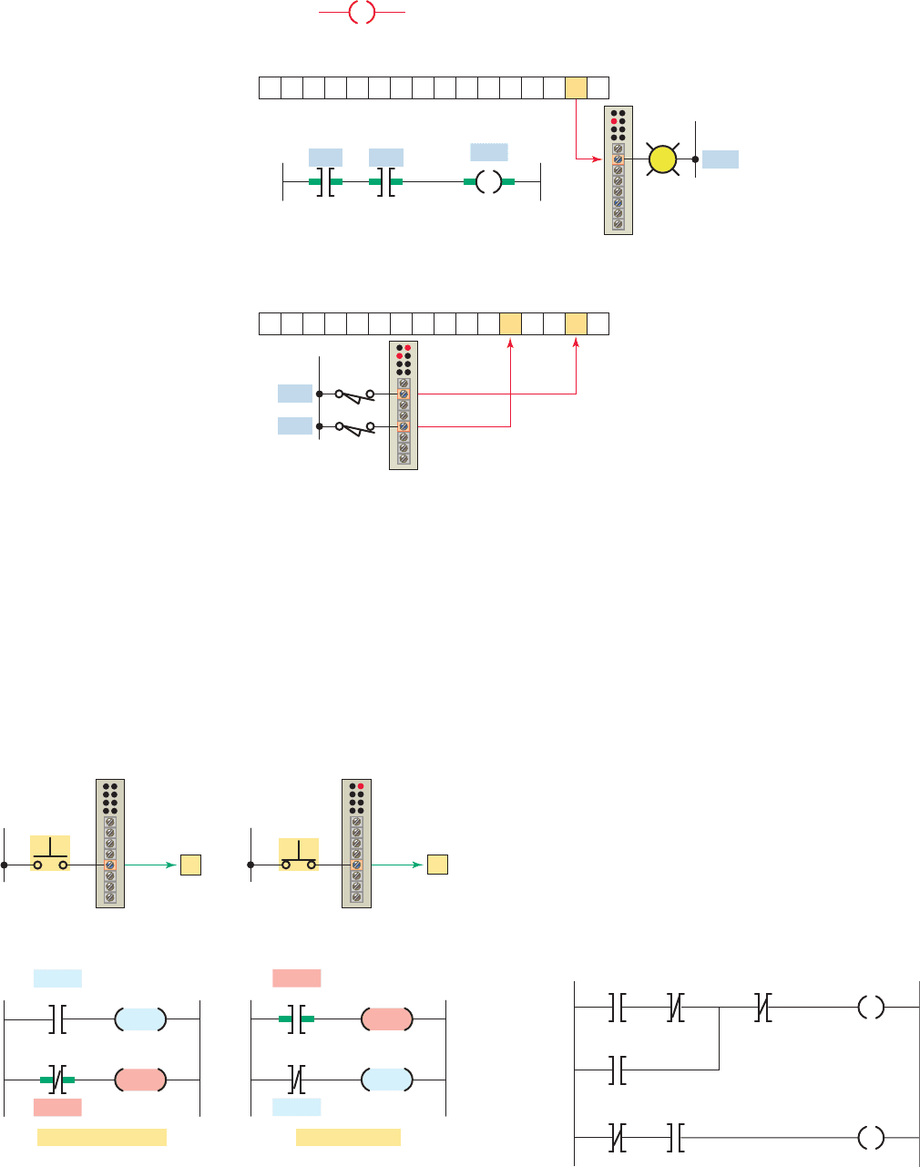
the action of the PLC bits as illustrated in Figure5-21 . A
signal present makes the NO bit (1) true; a signal absent
makes the NO bit (0) false. The reverse is true for an NC
bit. A signal present makes the NC bit (1) false; a signal
absent makes the NO bit (0) true.
The main function of the ladder logic diagram pro-
gram is to control outputs based on input conditions, as
illustrated in Figure 5-22 . This control is accomplished
through the use of what is referred to as a ladder rung. In
general, a rung consists of a set of input conditions, rep-
resented by contact instructions, and an output instruction
at the end of the rung, represented by the coil symbol.
Each contact or coil symbol is referenced with an address
that identi es what is being evaluated and what is being
controlled. The same contact instruction can be used
throughout the program whenever that condition needs to
be evaluated. The number of ladder logic relays and input
and output instructions is limited only by memory size.
Most PLCs allow more than one output per rung.
Figure 5-20 Output Energize (OTE) instruction.
Symbol
Output energize
Output
data
Input
data
Program
Ι:1/1
Ι:1/4
Ι:1/1
Ο:2/1
1514131211109876543210
ON
1514131211109876543210
1
11
Output
module
Input
module
Ι:1/4
Ο:2/1
Figure 5-21 Separating the action of the fi eld device and
PLC bit.
A
A
A
FALSE
Button not actuated
TRUE
OUTPUT
Input
module
Ladder logic program
Bit
status
OFF
A
ON
0
A
FALSE
Button actuated
TRUE
OUTPUT
Input
module
Ladder logic program
Bit
status
ON
1
OFF
A
Figure 5-22 Ladder logic diagram rungs.
I/3
I/2I/1
O/1
Inputs
Rung 0
Rung 1
Outputs
I/4
I/2
O/2
O/1
pet10882_ch05_071-094.indd 83pet10882_ch05_071-094.indd 83 7/23/10 9:14 PM7/23/10 9:14 PM
84 Chapter 5 Basics of PLC Programming
The addressing of real inputs and outputs, as well as
internals, depends on the PLC model used. Addressing
formats can vary from one PLC family to another as well
as for different manufacturers. These addresses can be
represented in decimal, octal, or hexadecimal depend-
ing on the number system used by the PLC. The address
identi es the function of an instruction and links it to a
particular bit in the data table portion of the memory.
Figure 5-24 shows the addressing format for an Allen-
Bradley SLC 500 controller. Addresses contain the slot
number of the module where input or output devices
are connected. Addresses are formatted as le type, slot
number, and bit.
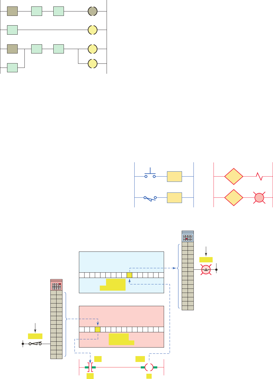
The assignment of an I/O address can be included in
the I/O connection diagram, as shown in Figure5-25 . In-
puts and outputs are typically represented by squares and
diamonds, respectively.
For an output to be activated or energized, at least one
left-to-right true logical path must exist, as illustrated in
Figure5-23 . A complete closed path is referred to as hav-
ing logical continuity. When logical continuity exists in
at least one path, the rung condition and Output Energize
instruction are said to be true. The rung condition and
OTE instruction are false if no logical continuity path has
been established. During controller operation, the proces-
sor evaluates the rung logic and changes the state of the
outputs according to the logical continuity of rungs.
5.5 Instruction Addressing
To complete the entry of a relay-type instruction, you
must assign an address to each instruction. This address
indicates what PLC input is connected to what input de-
vice and what PLC output will drive what output device.
Figure 5-23 Logical continuity.
Rung 0
Rung 1
Rung 2
FTTF
TTTF
TT
T
T
Figure 5-24 Addressing format for an Allen-Bradley SLC 500 controller.
Closed
switch
Energized
output
Output image table
file 0
User-programmed rung
O:4/6
Bit address
6
12
Ι:3 O:4
Ι:3/12
Input file (I)
Slot (3)
Bit (12)
L1
Input image table
file 1
0 0 0 1 0 0 0 0 0 0 0 0 0 0 0 0
0 0 0 0 0 0 0 0 0 1 0 0 0 0 0 0
Ι:3/12
Bit address
0
1
2
3
4
5
6
7
8
9
10
11
12
13
14
15
Ο:4/6
Output file (O)
Slot (4)
Bit (6)
L2
0
1
2
3
4
5
6
7
8
9
10
11
12
13
14
15
Figure 5-25 I/O connection diagram.
O:3/6
Outputs
LL
Inputs
LS1
LL
PB1
SOL1
O:2/3
121
PL1
2
I:4/5
I:4/6
R
pet10882_ch05_071-094.indd 84pet10882_ch05_071-094.indd 84 7/28/10 9:14 PM7/28/10 9:14 PM

Basics of PLC Programming Chapter 5 85
Additional input logic instructions (conditions) can
be programmed in the output branches to enhance con-
ditional control of the outputs. When there is a true
logic path, including extra input conditions on an output
branch, that branch becomes true. In the example shown
in Figure5-29 , either A and D or B and D provide a true
logic path to E.
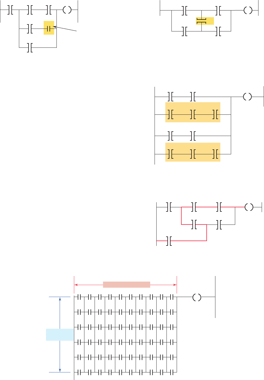
Input and output branches can be nested to avoid
redundant instructions and to speed up processor scan
time. Figure 5-30 illustrates nested input and output
branches. A nested branch starts or ends within another
branch.
In some PLC models, the programming of a branch
circuit within a branch circuit or a nested branch can-
not be done directly. It is possible, however, to program
a logically equivalent branching condition. Figure5-31
shows an example of a circuit that contains a nested
contact D. To obtain the required logic, the circuit
would be programmed as shown in Figure 5-32 . The
duplication of contact C eliminates the nested con-
tact D. Nested branching can be converted into non-
nested branches by repeating instructions to make par-
allel equivalents.
5.6 Branch Instructions
Branch instructions are used to create parallel paths of
input condition instructions. This allows more than one
combination of input conditions (OR logic) to establish
logic continuity in a rung. Figure5-26 illustrates a typical
branch instruction. The rung will be true if either instruc-
tion A or B is true.
Input branching by formation of parallel branches can
be used in your application program to allow more than
one combination of input conditions. If at least one of these
parallel branches forms a true logic path, the rung logic is
true and the output will be energized. If none of the paral-
lel branches complete a logical path, logic rung continuity
is not established and the output will not be de-energized.
In the example shown in Figure5-27 , either A and B, or C
provides logical continuity and energizes output D.
On most PLC models, branches can be established
at both input and output portions of a rung. With output
branching, you can program parallel outputs on a rung to
allow a true logic path to control multiple outputs, as il-
lustrated in Figure5-28 . When there is a true logic rung
path, all parallel outputs become true. In the example
shown, either A or B provides a true logical path to all
three output instructions: C, D, and E.
Figure 5-26 Typical branch instruction.
A
B
C
Figure 5-27 Parallel input branches.
B
D
C
A
Figure 5-28 Parallel output branches.
B
D
E
C
A
Figure 5-29 Parallel output branching with conditions.
BD
E
C
A
Figure 5-30 Nested input and output branches.
Figure 5-31 Nested contact program.
A branch within
a branch
Y
ABC
D
E
pet10882_ch05_071-094.indd 85pet10882_ch05_071-094.indd 85 7/23/10 9:14 PM7/23/10 9:14 PM
86 Chapter 5 Basics of PLC Programming
Figure 5-33 PLC matrix limitation diagram.
Maximum 7
parallel lines
Maximum 10 contacts
Figure 5-34 Program with vertical contact.
Boolean equation: Y ⫽ (AD) ⫹ (BCD) ⫹ (BE ) ⫹ (ACE )
AD
BE
C
Y
Figure 5-35 Reprogrammed to eliminate vertical contact.
YDA
CDB
CEA
EB
Some PLC manufacturers have virtually no limitations
on allowable series elements, parallel branches, or out-
puts. For others, there may be limitations to the number of
series contact instructions that can be included in one rung
of a ladder diagram as well as limitations to the number
of parallel branches. Also, there is an additional limitation
with some PLCs: only one output per rung and the output
must be located at the end of the rung. The only limita-
tion on the number of rungs is memory size. Figure5-33
shows the matrix limitation diagram for a typical PLC. A
maximum of seven parallel lines and 10 series contacts
per rung is possible.
Another limitation to branch circuit programming is
that the PLC will not allow for programming of vertical
contacts. A typical example of this limitation is contact
C of the user program drawn in Figure 5-34 . To obtain
the required logic, the circuit would be reprogrammed as
shown in Figure5-35 .
The processor examines the ladder logic rung for logic
continuity from left to right only. The processor never al-
lows for ow from right to left. This situation presents a
problem for user program circuits similar to that shown in
Figure5-36 . If programmed as shown, contact combination
FDBC would be ignored. To obtain the required logic, the
circuit would be reprogrammed as shown in Figure5-37 .
Figure 5-36 Original circuit.
Boolean equation: Y ⫽ (ABC) ⫹ (ADE) ⫹ (FE) ⫹ (FDBC)
A
E
B
D
F
C
Y
Figure 5-32 Program required to eliminate nested
contact.
ABC
Y
C
D
E
Contact
instruction C
repeated
pet10882_ch05_071-094.indd 86pet10882_ch05_071-094.indd 86 7/23/10 9:14 PM7/23/10 9:14 PM

Basics of PLC Programming Chapter 5 87
Internal outputs are single-bit storage locations in
memory and are addressed as such. SLC 500 controllers
use bit le B3 for storage and addressing of internal out-
put bits. The addressing for bit B3:1/3 illustrated in Fig-
ure5-38 consists of the le number followed by word and
bit numbers.
An internal control relay can be used when a program
requires more series contacts than the rung allows. Fig-
ure5-39 shows a circuit that allows for only 7 series con-
tacts when 12 are actually required for the programmed
logic. To solve this problem, the contacts are split into
two rungs. Rung 1 contains seven of the required con-
tacts and is programmed to control internal relay coil
B3:1/3. The address of the rst programmed contact on
Rung 2 is B3:1/3 followed by the remaining ve contacts
and the discrete output. When the logic controlling the
internal output is true, the referenced bit B3:1/3 is turned
on or set to 1. The advantage of an internal storage bit in
this manner is that it does not waste space in a physical
output.
5.7 Internal Relay Instructions
Most PLCs have an area of the memory allocated for what
are known as internal storage bits. These storage bits are
also called internal outputs, internal coils, internal con-
trol relays, or simply internal bits. Internal outputs are on/
off signals generated by programmed logic. Unlike a dis-
crete output, an internal output does not directly control
an output eld device. The internal output operates just
like any output that is controlled by programmed logic;
however, the output is used strictly for internal purposes.
The advantage of using internal outputs is that there
are many situations in which an output instruction is re-
quired in a program but no physical connection to a eld
device is needed. If there are no physical outputs wired
to a bit address, the address can be used as an internal
storage point. Internal storage bits or points can be pro-
grammed by the user to perform relay functions without
occupying a physical output. In this way internal outputs
can minimize output module point requirements when-
ever practical.
Figure 5-37 Reprogrammed circuit.
CB
ADE
C
A
EF
FDB
Y
Figure 5-38 SLC 500 controllers use bit fi le B3 for internal bit
addressing.
0
Output File
1
Input File
2
Status File
File (B3)
Word (1)
Bit (3)
B3:0 1 1 1 1 0 0 1000000000
0000100000100010
0000010000000000
0000000000000000
0000000000000000
0000000000000000
0000000000000000
B3:1
B3:2
B3:3
B3:4
B3:5
B3:6
Bit File
3
Address
B3:1/3
Data File B3 (bin) -- BINARY
Offset
1514131211109876543210
3
Bit File
4
Timer File
5
Counter File
6
Control Files
7
Integer Files
Figure 5-39 Programmed internal relay control.
21 345
98 101112
67
Internal
relay
coil
B3:1/3
Discrete
output
Discrete inputs
Discrete inputs
Rung 1
Rung 2
Internal
relay
contact
B3:1/3
pet10882_ch05_071-094.indd 87pet10882_ch05_071-094.indd 87 7/23/10 9:14 PM7/23/10 9:14 PM

88 Chapter 5 Basics of PLC Programming
symbol. This is because the normal state of an input (NO
or NC) does not matter to the controller. What does matter
is that if contacts need to close to energize the output, then
the Examine If Closed instruction is used. Since both PB1
and PB2 must be closed to energize the pilot light, the
Examine If Closed instruction is used for both.
A simple program using the Examine If Open (XIO)
instruction is shown in Figure5-41 . Both the hardwired
circuit and user program are shown. In the hardwired cir-
cuit, when the pushbutton is open relay coil CR is de-
energized and its NO contact closes to switch the pilot
light on. When the pushbutton is closed, relay coil CR
is energized and its NC contact opens to switch the pilot
light off. The pushbutton is represented in the user pro-
gram by an Examine If Open instruction. This is because
the rung must be true when the external pushbutton is
open and false when the pushbutton is closed. Using an
Examine If Open instruction to represent the pushbutton
satis es these requirements. The NO or NC mechanical
action of the pushbutton is not a consideration. It is im-
portant to remember that the user program is not an elec-
trical circuit but a logic circuit. In effect, we are interested
in logic continuity when establishing an output.
Figure 5-42 shows a simple program using both the
XIC and XIO instructions. The logic states (0 or 1) indi-
cate whether an instruction is true or false and is the basis
5.8 Programming Examine If Closed
and Examine If Open Instructions
A simple program using the Examine If Closed (XIC)
instruction is shown in Figure5-40 . This gure shows a
hardwired circuit and a user program that provides the
same results. You will note that both the NO and the NC
pushbuttons are represented by the Examine If Closed
Figure 5-40 Simple program that uses the Examine If
Closed (XIC) instruction.
Hardwired circuit
PL
PLPB_2PB_1
PB2
PB1
User program providing
the same results
Figure 5-41 Simple program that uses the Examine If
Open (XIO) instruction.
Hardwired circuit
CR
PB1
CR
PL
User program providing
the same results
PB_1
PL
Figure 5-42 Simple program using both the XIC and XIO instructions.
The status of the instruction is
If the data table bit
is
X
IC
EXAMINE IF CLOSED
False
FalseTr ue
False False
False
False
False
True
Tr ue
F
alse
Tr ue
Tr ueLogic 0
Logic 1
X
IO
EXAMINE IF OPEN
OTE
OUTPUT ENERGIZE
XIC
Instruction outcome
Time
t
1
(initial)
t
2
t
3
t
4
Input bit status
XIO
OT
E
XIC
XIO
OTE
000
101
110
01
0
Tr ue
True Goes true
Goes false
Remains false
XIC
X
IO
OTE
Input instructions Output instruction
pet10882_ch05_071-094.indd 88pet10882_ch05_071-094.indd 88 7/23/10 9:14 PM7/23/10 9:14 PM

Basics of PLC Programming Chapter 5 89
from other rungs in the project. There are several different
methods that you can use to address instructions. You can
enter an address by manually typing it in or by dragging
the address from data les or other instructions.
Some of the windows you will need to use when work-
ing with RSLogix 500 software include:
• Main Window —This window opens each time you
create a new project or open an existing one. Some
of the features associated with this window include
the following:
- Window Title Bar—The title bar is located at
the topmost strip of the window and displays
the name of the program as well as that of the
opened le.
- Menu Bar—The menu bar is located below the
title bar. The menu contains key words associated
with menus that are opened by clicking on the
key word.
- Windows Toolbar—The Windows toolbar buttons
execute standard Windows commands when you
click on them.
- Program/Processor Status Toolbar—This toolbar
contains four drop-down lists that identify the
current processor operating mode, current online
edit status, and whether forces are present and
enabled.
- Project Window—This window displays the le
folders listed in the project tree.
of controller operation. The gure summarizes the on/off
state of the output as determined by the changing states
of the inputs in the rung. The time aspect relates to the
repeated scans of the program, wherein the input table is
updated with the most current status bits.
5.9 Entering the Ladder Diagram
Most of today’s PLC programming packages operate in
the Windows environment. For example, Allen-Bradley’s
RSLogix software packages are Windows programming
packages used to develop ladder logic programs. This
software, in various versions, can be used to program the
PLC-5, SLC 500, ControlLogix, and MicroLogic family
of processors. An added feature is that RSLogix programs
are compatible with programs that have been previously
created with DOS-based programming packages. You can
import projects that were developed with DOS products
or export to them from RSLogix.
Entering the ladder diagram, or actual programming,
is usually accomplished with a computer keyboard or
hand-held programming device. Because hardware and
programming techniques vary with each manufacturer, it
is necessary to refer to the programming manual for a spe-
ci c PLC to determine how the instructions are entered.
One method of entering a program is through a hand-
held keyboard. Keyboards usually have relay symbol
and special function keys along with numeric keys for
addressing. Some also have alphanumeric keys (letters
and numbers) for other special programming functions.
In hand-held units, the keyboard is small and the keys
have multiple functions. Multiple-function keys work like
second-function keys on calculators.
A personal computer is most often used today as the
programmer. The computer is adapted to the particular
PLC model through the use of the relevant programmable
controller software.
Figure5-43 shows the RSLogix SLC 500 main win-
dow. Different screens, toolbars, and dialog boxes are
used to navigate through the Windows environment. It is
important that you understand the purpose of the various
screens, toolbars, and windows to make the most effective
use of the software. This information is available from the
software reference manual for the particular PLC family
and will become more familiar to you as you develop pro-
grams using the software.
Figure5-44 shows a typical instruction toolbar with bit
instructions selected. To place an instruction on a rung,
click its icon on the toolbar and simply drag the instruc-
tion straight off the toolbar onto the rung of the ladder.
Drop points are shown on the ladder to help position the
instruction. In addition, instructions can also be dragged
Figure 5-43 RSLogix SLC 500 main window.
Source: Image Used with Permission of Rockwell Automation, Inc.
Figure 5-44 Typical instruction toolbar with bit
instructions selected.
OSR
Bit
User
Timer/Counter Input/Output Compare
L U
pet10882_ch05_071-094.indd 89pet10882_ch05_071-094.indd 89 7/27/10 10:12 PM7/27/10 10:12 PM

90 Chapter 5 Basics of PLC Programming
• I/O Con guration —The I/O Con guration screen
( Figure5-46 ) lets you click or drag-and-drop a
module from an all-inclusive list to assign it to a slot
in your con guration.
• Data Files —Data File screens contain data that are
used in conjunction with ladder program instruc-
tions and include input and output les as well as
timer, counter, integer, and bit les. Figure5-47
shows an example of the bit le B3, which is used
for internal relays. Note that all the addresses from
this le start with B3.
Relay ladder logic is a graphical programming language
designed to closely represent the appearance of a wired
relay system. It offers considerable advantages for PLC
control. Not only is it reasonably intuitive, especially for
users with relay experience, but it is also particularly effec-
tive in an online mode when the PLC is actually perform-
ing control. Operation of the logic is apparent from the
highlighting of rungs of the various instructions on-screen,
- Project Tree—The project tree is a visual repre-
sentation of all folders and their associated les
contained in the current project. From the project
tree, you can open les, create les, modify le
parameters, copy les, hide or unhide les, delete
les, and rename les.
- Result Window—This window displays the re-
sults of either a search or a verify operation. The
verify operation is used to check the ladder pro-
gram for errors.
- Active Tab—This tab identi es which program is
currently active.
- Status Bar—This bar contains information rel-
evant to the current le.
- Split Bar—The split bar is used to split the ladder
window to display two different program les or
groups of ladder rungs.
- Tabbed Instruction Toolbar—This toolbar dis-
plays the instruction set as a group of tabbed
categories.
- Instruction Palette—This tool contains all the
available instructions displayed in one table to
make the selection of instructions easier.
- Ladder Window—This window displays the cur-
rently open ladder program le and is used to
develop and edit ladder programs.
- Ladder Window Properties—This window allows
you to change the display of your ladder program
and its associated addressing and documentation.
• Select Processor Type —The programming soft-
ware needs to know what processor is being used in
conjunction with the user program. The Select Pro-
cessor Type screen ( Figure5-45 ) contains a list of
the different processors that the RSLogix software
can program. You simply scroll down the list until
you nd the processor you are using and select it.
Figure 5-45 Select processor type screen.
Figure 5-46 I/O confi guration screen.
Figure 5-47 Data bit fi le B3 screen.
pet10882_ch05_071-094.indd 90pet10882_ch05_071-094.indd 90 7/23/10 9:14 PM7/23/10 9:14 PM
Basics of PLC Programming Chapter 5 91
Some common operating modes are explained in the
following paragraphs.
Program Mode The program mode is used to enter
a new program, edit or update an existing program,
upload les, download les, document (print out) pro-
grams, or change any software con guration le in the
program. When the PLC is switched into the program
mode, all outputs from the PLC are forced off regard-
less of their rung logic status, and the ladder I/O scan
sequence is halted.
Run Mode The run mode is used to execute the user
program. Input devices are monitored and output de-
vices are energized accordingly. After all instructions
have been entered in a new program or all changes
made to an existing program, the processor is put in
the run mode.
Test Mode The test mode is used to operate or
monitor the user program without energizing any
outputs. The processor still reads inputs, executes
the ladder program, and updates the output status
table les, but without energizing the output cir-
cuits. This feature is often used after developing
or editing a program to test the program execu-
tion before allowing the PLC to operate real-world
outputs. Variations of the test mode can include
the single-step test mode, which directs the proces-
sor to execute a selected single rung or group of
rungs; the single-scan test mode, which executes
a single processor operating scan or cycle; and the
continuous-scan test mode, which directs the pro-
cessor to continuously run the program for checking
or troubleshooting.
Remote Mode Some processors have a three-
position switch to change the processor operating
mode. In the Run position, all logic is solved and the
I/O is enabled. In the Program position, all logic solv-
ing is stopped and the I/O is disabled. The Remote
position allows the PLC to be remotely changed
between program and run mode by a personal com-
puter connected to the PLC processor. The remote
mode may be bene cial when the controller is in a
location that is not easily accessible.
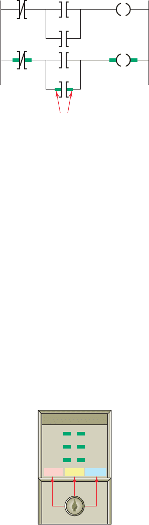
which identi es the logic state of contacts in real time ( Fig-
ure5-48 ) and which rungs have logic continuity.
For most PLC systems, each Examine If Closed and
Examine If Open contact, each output, and each branch
Start/End instruction requires one word of user memory.
You can refer to the SLC 500 Controller Properties to see
the number of instruction words used and the number left
as the program is being developed.
5.10 Modes of Operation
A processor has basically two modes of operation: the
program mode and some variation of the run mode. The
number of different operating modes and the method of
accessing them varies with the manufacturer. Figure5-49
shows a typical three-position keyswitch used to select
different processor modes of operation.
Figure 5-48 Monitoring a ladder logic program.
Highlighted rungs indicate
the instruction is true.
Figure 5-49 Three-position keyswitch used to select
different processor modes of operation.
PROGREMRUN
pet10882_ch05_071-094.indd 91pet10882_ch05_071-094.indd 91 7/23/10 9:14 PM7/23/10 9:14 PM

92 Chapter 5 Basics of PLC Programming
1. What does the memory map for a typical PLC pro-
cessor consist of?
2. Compare the function of the PLC program and data
les.
3. In what manner are data les organized?
4. List eight different types of data les use by an
SLC 500 controller.
5. a. What information is stored in the input image
table le?
b. In what form is this information stored?
6. a. What information is stored in the output image
table le?
b. In what form is this information stored?
7. Outline the sequence of events involved in a PLC
scan cycle.
8. List four factors that enter into the length of the
scan time.
9. Compare the way horizontal and vertical scan pat-
terns examine input and output instructions.
10. List the ve standard PLC languages as de ned by
the International Standard for Programmable Con-
trollers, and give a brief description of each.
11. Draw the symbol and state the equivalent instruc-
tion for each of the following: NO contact, NC
contact, and coil.
12. Answer the following with regard to the Examine If
Closed instruction:
a. What is another common name for this instruction?
b. What is this instruction asking the processor to
examine?
c. Under what condition is the status bit associated
with this instruction 0?
d. Under what condition is the status bit associated
with this instruction 1?
e. Under what condition is this instruction logically
true?
f. What state does this instruction assume when it
is false?
13. Answer the following with regard to the Examine If
Open instruction:
a. What is another common name for this
instruction?
b. What is this instruction asking the processor to
examine?
c. Under what condition is the status bit associated
with this instruction 0?
d. Under what condition is the status bit associated
with this instruction 1?
e. Under what condition is this instruction logically
true?
f. What state does this instruction assume when it
is false?
14. Answer the following with regard to the Output En-
ergize instruction:
a. What part of an electromagnetic relay does this
instruction look and act like?
b. What is this instruction asking the processor to do?
c.
Under what condition is the status bit associated
with this instruction 0?
d.
Under what condition is the status bit associated
with this instruction 1?
15. A normally closed pushbutton is connected to a
PLC discrete input. Does this mean it must be rep-
resented by a normally closed contact in the ladder
logic program? Explain why or why not.
16. Answer the following with regard to a ladder logic
rung:
a. Describe the basic makeup of a ladder logic
rung.
b. How are the contacts and coil of a rung
identi ed?
c. When is the ladder rung considered as having
logic continuity?
17. What does the address assigned to an instruction
indicate?
18. When are input branch instructions used as part of
a ladder logic program?
19. Identify two matrix limitations that may apply to
certain PLCs.
20. In what way does an internal output differ from a
discrete output.
21. A normally open limit switch is to be programmed
to control a solenoid. What determines whether an
Examine-on or Examine-off contact instruction is
used?
22. Explain the purpose of Windows based program-
ming software such as RSLogix.
23. Brie y describe each of the following PLC modes
of operation:
a. Program
b. Test
c. Run
CHAPTER 5 REVIEW QUESTIONS
pet10882_ch05_071-094.indd 92pet10882_ch05_071-094.indd 92 7/23/10 9:14 PM7/23/10 9:14 PM