Petruzella F.D. Programmable Logic Controllers
Подождите немного. Документ загружается.

Basics of PLC Programming Chapter 5 73
processor set up for standard ladder logic, the main pro-
gram will always be in program le 2, and program les
3 through 999 will be subroutines. In either case, the pro-
cessor can store and execute only one program at a time.
Figure5-3 shows a typical data le memory organiza-
tion for an Allen-Bradley PLC-5 controller. Each data le
is made up of numerous elements. Each element may be
one, two, or three words in length. Timer, counter, and
control elements are three words in length; oating-point
elements are two words in length; and all other elements
are a single word in length. A word consists of 16 bits, or
binary digits. The processor operates on two different data
types: integer and oating point. All data types, except the
oating-point les, are treated as integers or whole num-
bers. All element and bit addresses in the output and input
data les are numbered octally. Element and bit addresses
in all other data les are numbered decimally.
The PLC-5 and SLC 500 store all data in global data
tables and are based on 16-bit operations. You access these
data by specifying the address of the data you want. Typical
addressing formats for the PLC-5 controller are as follows:
• The addresses in the output data le and the input
data le are potential locations for either input mod-
ules or output modules mounted in the I/O chassis:
- The address O:012/15 is in the output image
table le, rack 1, I/O group 2, bit 15.
- The address I:013/17 is in the input image table
le, rack 1, I/O group 3, bit 17.
• The status data le contains information about the
processor status:
- The address S:015 addresses word 15 of the
status le.
- The address S:027/09 addresses bit 9 in word 27
of the status le.
• Counter ( le 5) —This le stores the counter accu-
mulated and preset values and status bits.
• Control ( le 6) —This le stores the length, pointer
position, and status bit for speci c instructions such
as shift registers and sequencers.
• Integer ( le 7) —This le is used to store numerical
values or bit information.
• Reserved ( le 8) —This le is not accessible to the
user.
• Network communications ( le 9) —This le is
used for network communications if installed or
used like les 10–255.
• User-de ned ( les 10–255) —These les are user-
de ned as bit, timer, counter, control, and/or integer
data storage.
The I/O address format for the SLC family of PLCs is
shown in Figure5-2 . The format consists of the following
three parts:
P
art 1: I for input, and a colon to separate the module
type from the slot.
O for output and a colon to separate the module type
from the slot.
Part 2: The module slot number and a forward slash
to separate the slot from the terminal screw.
Part 3: The screw terminal number.
There are about 1000 program les for an Allen-
Bradley PLC-5 controller. These program les may be set
up in two ways: either (1) standard ladder logic program-
ming, with the main program in program le 2 and program
les 3 through 999 assigned, as needed, to subroutines; or
(2) in sequential function charts in which les 2 through
999 are assigned steps or transitions, as required. With the
Figure 5-2 I/O address format for the SLC family of PLCs.
Source: Image Used with Permission of Rockwell Automation, Inc.
00
01
02
03
04
05
06
07
08
09
10
11
12
13
14
15
00
01
02
03
04
05
06
07
08
09
10
12
13
14
15
I:1
O:2
0123
I : 1/2
O : 2/11
SeparatorInput or
output
Slot
number
Bit
number
Bit
designator
11
pet10882_ch05_071-094.indd 73pet10882_ch05_071-094.indd 73 7/23/10 9:14 PM7/23/10 9:14 PM
74 Chapter 5 Basics of PLC Programming
• The bit data le stores bit status. It frequently serves
for storage when using internal outputs, sequencers,
bit-shift instructions, and logical instructions:
- The address B3:400 addresses word 400 of the
bit le. The le number (3) must be included as
part of the address. Note that the input, output,
and status data les are the only les that do not
require the le number designator because there
can only be one input data, one output data, and
one status data le.
- Word 2, bit 15 is addressed as B3/47 because bit
numbers are always measured from the beginning
of the le. Remember that here, bits are num-
bered decimally (not octally, as the word repre-
senting the rack and slot).
• The timer le stores the timer status and timer data.
A timer element consists of three words: the control
word, preset word, and accumulated word. The ad-
dressing of the timer control word is the assigned
timer number. Timers in le 4 are numbered starting
with T4:0 and running through T4:999. The addresses
for the three timer words in timer T4:0 are:
The enable-bit address in the control word is T4:0/
EN, the timer-timing-bit address is T4:0/TT, and the
done-bit address is T4:0/DN.
• The counter le stores the counter status and coun-
ter data. A counter element consists of three words:
the control word, preset word, and accumulated
word. The addressing of the counter control is the
assigned counter number. Counters in le 5 are
numbered beginning with C5:0 and running through
C5:999. The addresses for the three counter words
in counter C5:0 are:
Figure 5-3 Data fi le memory organization for an Allen-Bradley PLC-5 controller.
Source: Image Used with Permission of Rockwell Automation, Inc.
Size, in
elements
Address
range
O:000
O:037
Ι:000
Ι:037
S:000
S:031
B3:000
B3:999
T4:000
T4:999
C5:000
C5:999
R6:000
R6:999
N7:000
N7:999
F8:000
F8:999
Output image file
Input image file
Processor status
Bit file
Timer file
Counter file
Control file
Integer file
Floating-point file
Files to be assigned file nos. 9–999
32
32
32
1–1000
1–1000
1–1000
1–1000
1–1000
1–1000
1–1000
per file
Control word: T4:0
Preset word: T4:0.PRE
Accumulated word: T4:0.ACC
Control word: C5:0
Preset word: C5:0.PRE
Accumulated word: C5:0.ACC
The count-up-enable-bit address in the control word
is C5:0/CU, the count-down-enable-bit address
is C5:0/CD, the done-bit address is C5:0/DN, the
over ow address is C5:0/OV, and the under ow ad-
dress is C5:0/UN.
• The control le stores the control element’s sta-
tus and data, and it is used to control various le
instructions. The control element consists of three
words: the control word, length word, and position
word. The addressing of the control’s control word
pet10882_ch05_071-094.indd 74pet10882_ch05_071-094.indd 74 7/23/10 9:14 PM7/23/10 9:14 PM
Basics of PLC Programming Chapter 5 75
is the assigned control number. Control elements in
control le 6 are numbered beginning with R6:0 and
running through R6:999. The addresses for the three
words in control element R6:0 are:
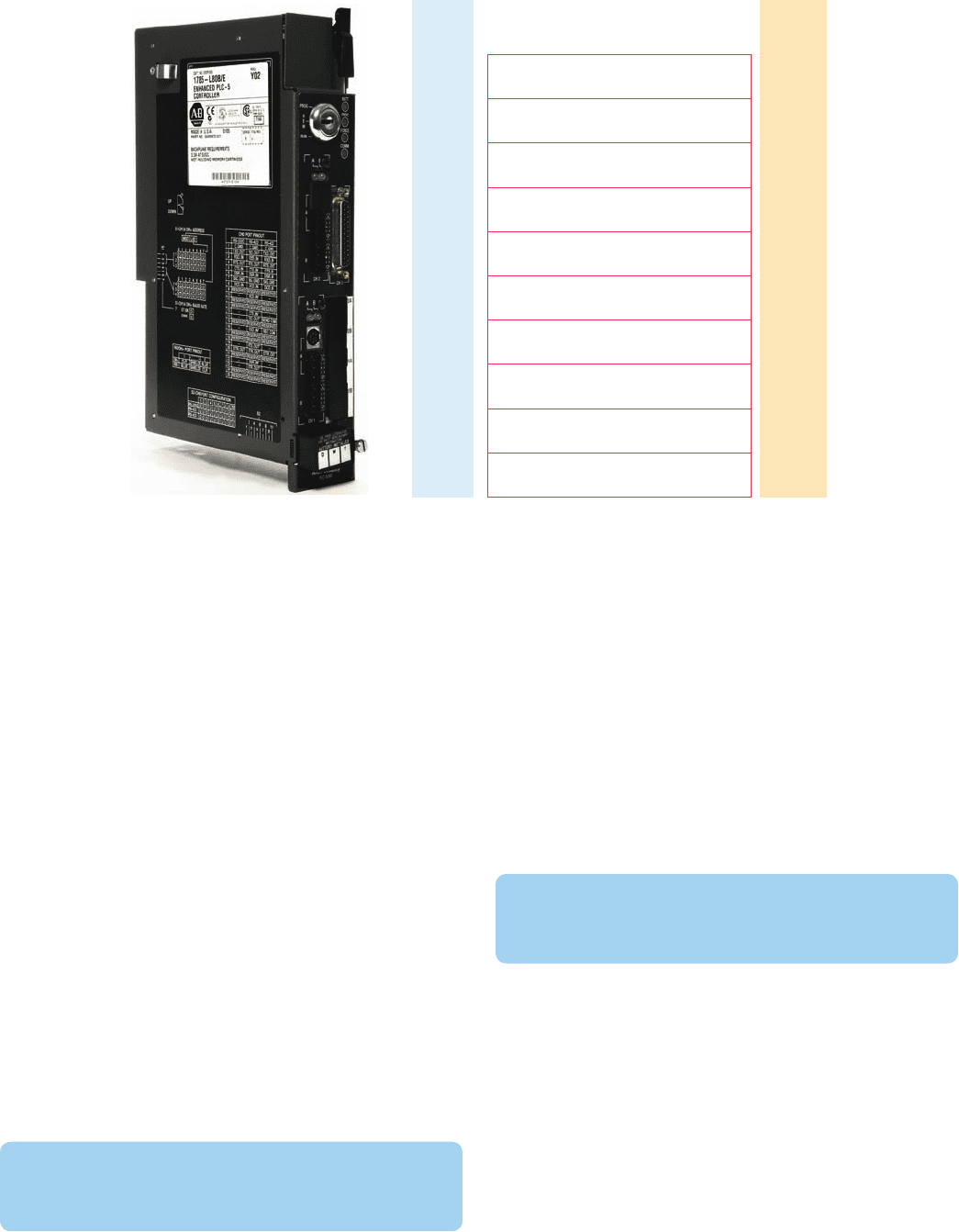
through the input module. Its operation can be summa-
rized as follows.
• For the switch that is closed, the processor detects a
voltage at the input terminal and records that infor-
mation by storing a binary 1 in its bit location.
• For the switch that is open, the processor detects no
voltage at the input terminal and records that infor-
mation by storing a binary 0 in its bit location.
• Each connected input has a bit in the input image
table le that corresponds exactly to the terminal to
which the input is connected.
• The input image table le is changed to re ect the
current status of the switch during the I/O scan
phase of operation.
• If the input is on (switch closed), its corresponding
bit in the table is set to 1.
• If the input is off (switch open), the corresponding
bit is cleared, or reset to 0.
• The processor continually reads the current input
status and updates the input image table le.
The output image table le is that part of the program
memory allocated to storing the actual on/off status of
connected discrete outputs. Figure 5-5 shows a typical
Control word: R6:0
Length: R6:0.LEN
Position: R6:0.POS
There are numerous control bits in the control word,
and their function depends on the instruction in
which the control element is used.
• The integer le stores integer data values, with a
range from 232,768 through 32,767. Stored values
are displayed in decimal form. The integer element
is a single-word (16-bit) element. As many as 1000
integer elements, addressed from N7:000 through
N7:999, can be stored.
- The address N7:100 addresses word 100 of the
integer le.
- Bit addressing is decimal, from 0 through 15.
For example, bit 12 in word 15 is addressed
N7:015/12.
• The oating-point le element can store val-
ues in the range from 61.1754944e-38 to
63.4028237e138. The oating-point element is a
two-word (32-bit) element. As many as 1000 ele-
ments, addressed from F8:000 through F8:999, can
be stored. Individual words or bits cannot be ad-
dressed in the oating-point le.
• Data les 9 through 999 may be assigned to dif-
ferent data types, as required. When assigned to a
certain type, a le is then reserved for that type and
cannot be used for any other type. Additional input,
output, or status les cannot be created.
The bit le, integer le, or oating-point le can be
used to store status or data. Which of these you use de-
pends on the intended use of the data. If you are deal-
ing with status rather than data, the bit le is preferable.
If you are using very large or very small numbers and
require a decimal point, the oating-point le is prefer-
able. The oating-point data type may have a restriction,
however, because it may not interface well with external
devices or with internal instructions such as counters and
timers, which use only 16-bit words. In such a situation, it
may be necessary to use the integer le type.
The input image table le is that part of the program
memory allocated to storing the on/off status of con-
nected discrete inputs. Figure5-4 shows the connection
of an open and closed switch to the input image table le
Figure 5-4 Connection of an open and closed switch to the
input image table fi le through the input module.
Input image
Word corresponding
to input module
ON
(closed)
(open)
Input module
OFF
L1
1
0
Data table
files
pet10882_ch05_071-094.indd 75pet10882_ch05_071-094.indd 75 7/23/10 9:14 PM7/23/10 9:14 PM
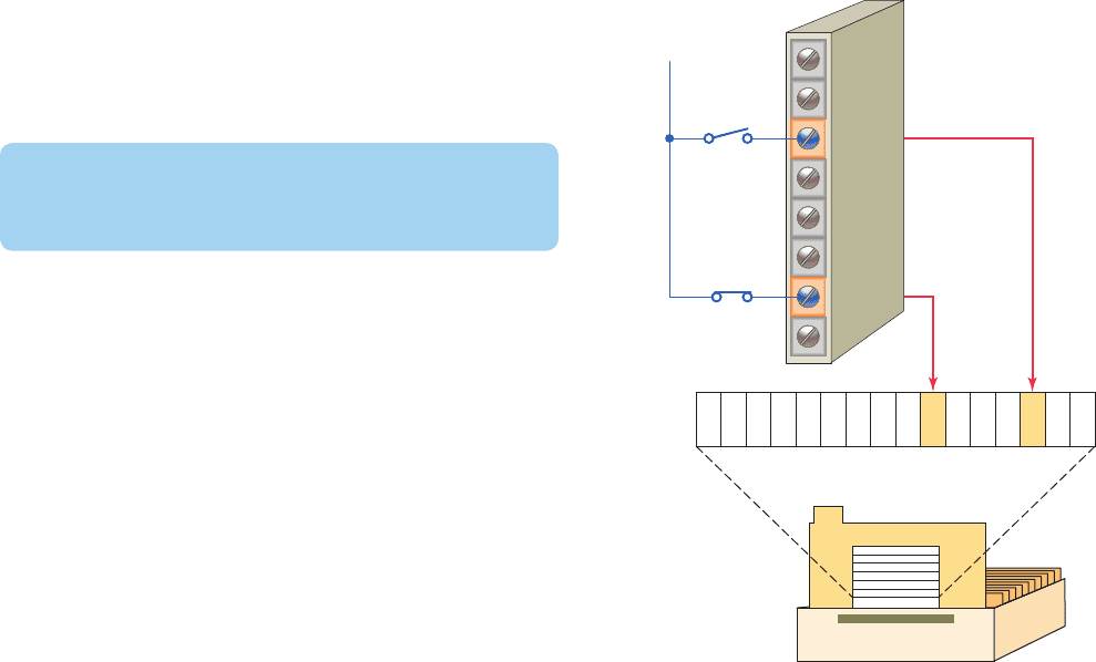
76 Chapter 5 Basics of PLC Programming
connection of two pilot lights to the output image table
le through the output module. Its operation can be sum-
marized as follows.
• The status of each light (ON/OFF) is controlled by
the user program and is indicated by the presence of
1 (ON) and 0 (OFF).
• Each connected output has a bit in the output image
table le that corresponds exactly to the terminal to
which the output is connected.
• If the program calls for a speci c output to be ON,
its corresponding bit in the table is set to 1.
• If the program calls for the output to be OFF, its
corresponding bit in the table is set to 0.
• The processor continually activates or deactivates the
output status according to the output table le status.
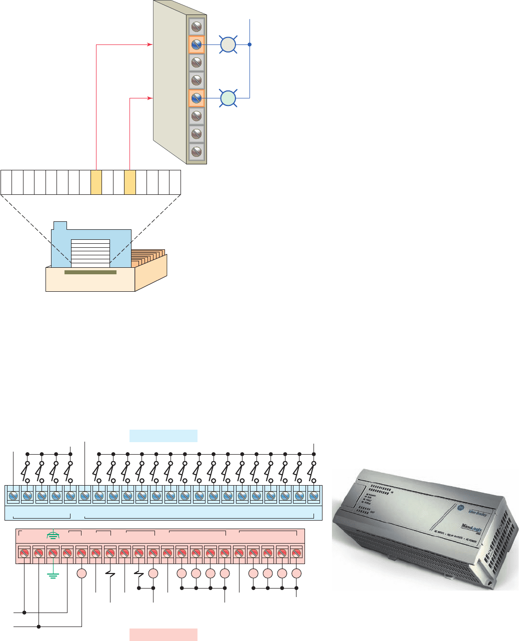
Typically, micro PLCs have a xed number of inputs
and outputs. Figure5-6 shows the MicroLogix control-
ler from the Allen-Bradley MicroLogix 1000 family of
controllers. The controller has 20 discrete inputs with
prede ned addresses I/0 through I/19 and 12 discrete
outputs with prede ned addresses O/1 through O/11.
Some units also contain analog inputs and outputs em-
bedded into the base unit or available through add-on
modules.
5.2 Program Scan
When a PLC executes a program, it must know—in real
time—when external devices controlling a process are
changing. During each operating cycle, the processor
reads all the inputs, takes these values, and energizes or
de-energizes the outputs according to the user program.
This process is known as a program scan cycle. Figure5-7
illustrates a single PLC operating cycle consisting of the
input scan, program scan, output scan, and housekeep-
ing duties. Because the inputs can change at any time, it
constantly repeats this cycle as long as the PLC is in the
RUN mode.
Figure 5-5 Connections of pilot lights to the output image
table fi le through the output module.
Output module
Output image
Word corresponding
to output module
OFF
L2
10
Data table
files
ON
Figure 5-6 Typical micro PLC with predefi ned addresses.
Source: Image Used with Permission of Rockwell Automation, Inc.
AC
COM
I/0 AC
COM
I/4 I/5 I/6 I/7 I/8 I/9 I/10 I/11 I/12 I/13 I/14 I/15 I/16 I/17 I/18 I/19I/1 I/2 I/3
VAC
VDC
VAC
VDC
VAC
VDC
VAC
VDC
O/4 O/2 O/3 O/4 O/5 O/6 O/7 O/8 O/9 O/10 O/11
VAC
VDC
O/0
L2
L2
L1
L1
VAC 2 VDC 1 VDC 2
VAC 2
COM
VDC 1
COM
VDC 2
COM
VDC 3
COM
VDC 3
L2
Discrete Inputs
Discrete Outputs
L1
CR CR CR CR CRCR CR CR CR CR
pet10882_ch05_071-094.indd 76pet10882_ch05_071-094.indd 76 7/23/10 9:14 PM7/23/10 9:14 PM
Basics of PLC Programming Chapter 5 77
The time it takes to complete a scan cycle is called the
scan cycle time and indicates how fast the controller can
react to changes in inputs. The time required to make a
single scan can vary from about 1 millisecond to 20mil-
liseconds. If a controller has to react to an input signal that
changes states twice during the scan time, it is possible
that the PLC will never be able to detect this change. For
example, if it takes 8 ms for the CPU to scan a program,
and an input contact is opening and closing every 4ms,
the program may not respond to the contact changing
state. The CPU will detect a change if it occurs during the
update of the input image table le, but the CPU will not
respond to every change. The scan time is a function of
the following:
• The speed of the processor module
• The length of the ladder program
• The type of instructions executed
• The actual ladder true/false conditions
The actual scan time is calculated and stored in the
PLC’s memory. The PLC computes the scan time each
time the END instruction is executed. Scan time data can
be monitored via the PLC programming. Typical scan
time data include the maximum scan time and the last
scan time.
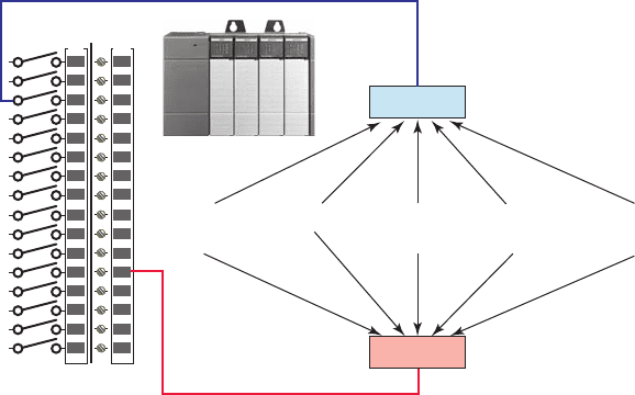
The scan is normally a continuous and sequential pro-
cess of reading the status of inputs, evaluating the control
logic, and updating the outputs. Figure5-8 shows an over-
view of the data ow during the scan process. For each
rung executed, the PLC processor will:
• Examine the status of the input image table bits.
• Solve the ladder logic in order to determine logical
continuity.
• Update the appropriate output image table bits, if
necessary.
• Copy the output image table status to all of the out-
put terminals. Power is applied to the output device
if the output image table bit has been previously set
to a 1.
• Copy the status of all of the input terminals to the
input image table. If an input is active (i.e., there is
electrical continuity), the corresponding bit in the
input image table will be set to a 1.
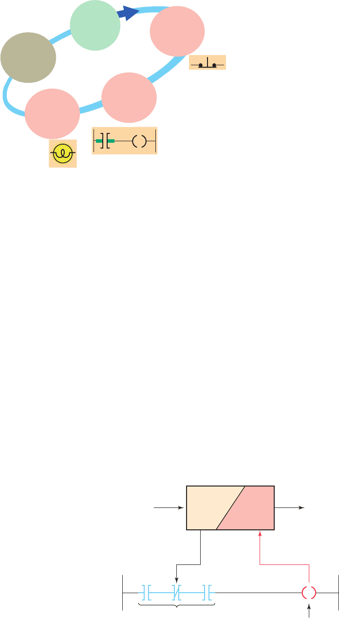
Figure5-9 illustrates the scan process applied to a sim-
ple single rung program. The operation of the scan pro-
cess can be summarized as follows:
• If the input device connected to address I:3/6 is
closed, the input module circuitry senses electrical
continuity and a 1 (ON) condition is entered into the
input image table bit I:3/6.
Figure 5-7 PLC program scan cycle.
Internal checks
on memory, speed
and operation.
Service any
communication
requests.
The output image
date is transferred
to the external output
circuits, turning the
output device
ON or OFF.
Each ladder rung
is scanned and solved
using the date in the
input file. The resulting
logic is written to the
output image table
(file or register).
The status of
external inputs
is written to the
input image table
(file or register).
HOUSE-
KEEPING
START
INPUT
SCAN
PROGRAM
SCAN
OUTPUT
SCAN
Figure 5-8 Overview of the data fl ow during the scan
process.
Input
modules
Input
data
Output
data
Input
image
table
file
Output
image
table
file
Return
result
Take some action
Examine
data
Check/compare/examine
specific conditions
Output
modules
Program
pet10882_ch05_071-094.indd 77pet10882_ch05_071-094.indd 77 7/23/10 9:14 PM7/23/10 9:14 PM
78 Chapter 5 Basics of PLC Programming
• During the program scan, the processor examines
bit I:3/6 for a 1 (ON) condition.
• In this case, because input I:3/6 is 1, the rung is said
to be TRUE or have logic continuity.
• The processor then sets the output image table bit
O:4/7 to 1.
• The processor turns on output O:4/7 during the next
I/O scan, and the output device (light) wired to this
terminal becomes energized.
• This process is repeated as long as the processor is
in the RUN mode.
• If the input device opens, electrical continuity is
lost, and a 0 would be placed in the input image
table. As a result, the rung is said to be FALSE due
to loss of logic continuity.
• The processor would then set the output image table
bit O:4/7 to 0, causing the output device to turn off.
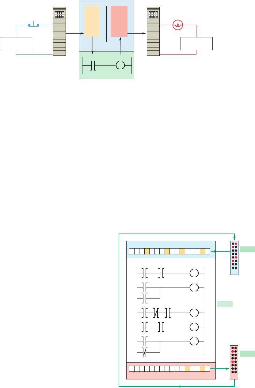
Ladder programs process inputs at the beginning of a
scan and outputs at the end of a scan, as illustrated in Fig-
ure5-10 . For each rung executed, the PLC processor will:
Step 1 Update the input image table by sensing the
voltage of the input terminals. Based on the
absence or presence of a voltage, a 0 or a 1 is
stored into the memory bit location designated
for a particular input terminal.
Step 2 Solve the ladder logic in order to determine
logical continuity. The processor scans the lad-
der program and evaluates the logical continu-
ity of each rung by referring to the input image
table to see if the input conditions are met. If
the conditions controlling an output are met, the
processor immediately writes a 1 in its memory
location, indicating that the output will be
turned ON; conversely, if the conditions are not
met a 0 indicating that the device will be turned
OFF is written into its memory location.
Step 3 The nal step of the scan process is to update
the actual states of the output devices by trans-
ferring the output table results to the output
module, thereby switching the connected out-
put devices ON (1) or OFF (0). If the status of
any input devices changes when the processor
is in step 2 or 3, the output condition will not
react to them until the next processor scan.
Each instruction entered into a program requires a cer-
tain amount of time for the instruction to be executed. The
amount of time required depends on the instruction. For
example, it takes less time for a processor to read the sta-
tus of an input contact than it does to read the accumu-
lated value of a timer or counter. The time taken to scan
Figure 5-9 Scan process applied to a single rung program.
Input
module
Input
device
Output
device
Input
image
table
file
Output
image
table
file
Output
module
Program
Data
Processor memory
O:4/7
O:4/7
Ι:3/6 O:4/7
Ι:3/6
Ι:3/6
Field-device
power supply
Field-device
power supply
Figure 5-10 Scan process applied to a multiple rung
program.
START
Input image table
000 000 00 00011110
Output image table
END
000 000 00 10000010
Step 3
Transfer
to output
module
Step 1
Read
input
module
Step 2
Solve the
ladder program
pet10882_ch05_071-094.indd 78pet10882_ch05_071-094.indd 78 7/29/10 9:39 PM7/29/10 9:39 PM
Basics of PLC Programming Chapter 5 79
the user program is also dependent on the clock frequency
of the microprocessor system. The higher the clock fre-
quency, the faster is the scan rate.
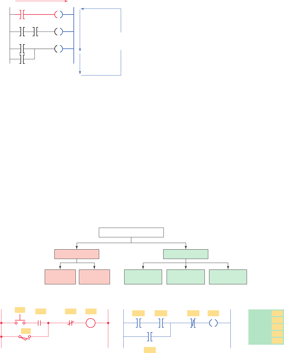
There are two basic scan patterns that different PLC
manufacturers use to accomplish the scan function
( F igure 5-11 ). Allen-Bradley PLCs use the horizontal
scan by rung method. In this system, the processor exam-
ines input and output instructions from the rst com-
mand, top left in the program, horizontally, rung by rung.
Modicon PLCs use the vertical scan by column method.
In this system, the processor examines input and output
instructions from the top left command entered in the lad-
der diagram, vertically, column by column and page by
page. Pages are executed in sequence. Both methods are
appropriate; however, misunderstanding the way the PLC
scans a program can cause programming bugs.
5.3 PLC Programming Languages
The term PLC programming language refers to the
method by which the user communicates information to
the PLC. The standard IEC 61131 ( Figure5-12 ) was es-
tablished to standardize the multiple languages associated
with PLC programming by de ning the following ve
standard languages:
• Ladder Diagram (LD) —a graphical depiction of a
process with rungs of logic, similar to the relay lad-
der logic schemes that were replaced by PLCs.
• Function Block Diagram (FBD) —a graphical de-
piction of process ow using simple and complex
interconnecting blocks.
• Sequential Function Chart (SFC) —a graphical
depiction of interconnecting steps, actions, and
transitions.
• Instruction List (IL) —a low-level, text-based
language that uses mnemonic instructions.
• Structured Text (ST) —a high-level, text-based lan-
guage such as BASIC, C, or PASCAL speci cally
developed for industrial control applications.
Ladder diagram language is the most commonly used
PLC language and is designed to mimic relay logic. The
ladder diagram is popular for those who prefer to de-
ne control actions in terms of relay contacts and coils,
and other functions as block instructions. Figure 5-13
shows a comparison of ladder diagram programming
and instruction list programming. Figure 5-13a shows
Figure 5-11 Scanning can be vertical or horizontal.
Horizontal scanning order
End of ladder
Vertical
scanning
order
Return
for next
scan
Figure 5-12 Standard IEC 61131 languages associated with PLC programming.
PLC programming languages
Textural language
Instruction
list
Structured
text
Sequential
function chart
Functional
block diagram
Ladder
diagram
Graphical language
Figure 5-13 Comparison of ladder diagram and instruction list programming.
PB1
CR CR SOL
LS
1
12
(a) Hardwired relay control circuit
SOL
AB DY
(LS1)
SOL
PB1
CR1
CR2
START
AND
OR
AND NOT
OUT
LS1
(CR2)(CR1)(PB1)
(b) Equivalent ladder diagram (LD) program (c) Equivalent instruction
list (IL) program
C
pet10882_ch05_071-094.indd 79pet10882_ch05_071-094.indd 79 7/23/10 9:14 PM7/23/10 9:14 PM
80 Chapter 5 Basics of PLC Programming
the original relay hardwired control circuit. Figure5-13b
shows the equivalent logic ladder diagram programmed
into a controller. Note how closely the ladder diagram
program closely resembles the hardwired relay circuit.
The input/output addressing is generally different for
each PLC manufacturer. Figure 5-13c show how the
original hardwired circuit could be programmed using
the instruction list programming language. Note that
the instructional list consists of a series of instructions
that refer to the basic AND, OR, and NOT logic gate
functions.
Functional block diagram programming uses instruc-
tions that are programmed as blocks wired together on
screen to accomplish certain functions. Typical types of
function blocks include logic, timers, and counters. Func-
tional block diagrams are similar in layout to electrical/
electronic block diagrams used to simplify complex sys-
tems by showing blocks of functionality. The primary
concept behind a functional block diagram is data ow.
Function blocks are linked together to complete a circuit
that satis es a control requirement. Data ow on a path
from inputs, through function blocks or instructions, and
then to outputs.
The use of function blocks for programming of pro-
grammable logic controllers (PLCs) is gaining wider
acceptance. Rather than the classic contact and coil repre-
sentation of ladder diagram or relay ladder logic program-
ming, function blocks present a graphical image to the
programmer with underlying algorithms already de ned.
The programmer simply completes needed information
within the block to complete that phase of the program.
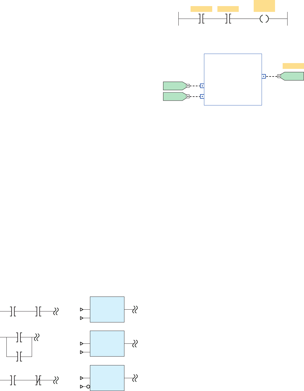
Figure5-14 shows function block diagram equivalents to
ladder logic contacts.
Figure5-15 illustrates how ladder diagram and func-
tional block diagram programming could be used to pro-
duce the same logical output. For this application, the
objective is to turn on caution pilot light PL 1 whenever
both sensor switch 1 and sensor switch 2 are closed. The
ladder logic consists of a single rung across the power
rails. This rung contains the two input sensor instructions
programmed in series with the pilot light output instruc-
tion. The function block solution consists of a logic Bool-
ean And function block with two input references tags for
the sensors and a single output reference tag for the pilot
light. Note there are no power rails in the function block
diagram.
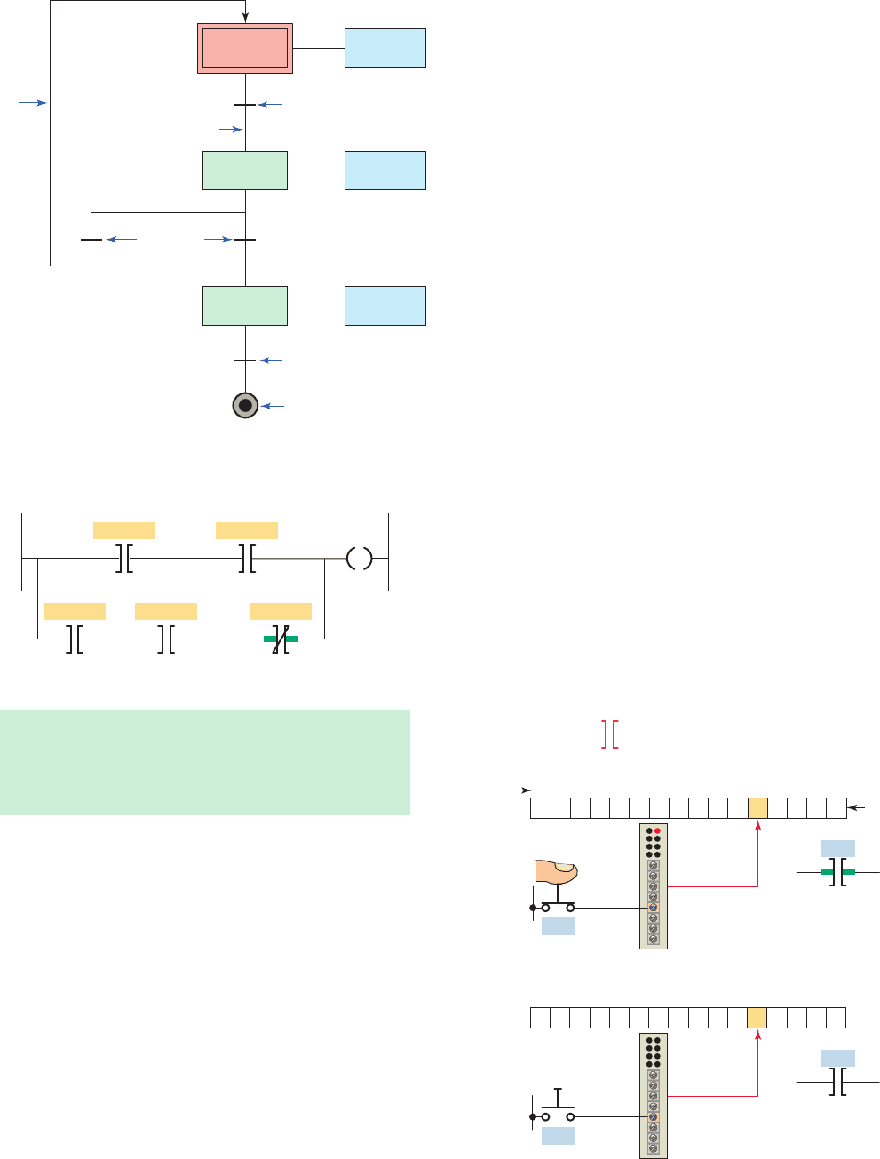
Sequential function chart programming language is
similar to a owchart of your process. SFC programming
is designed to accommodate the programming of more
advanced processes. This type of program can be split
into steps with multiple operations happening in paral-
lel branches. The basic elements of a sequential function
chart program are shown in Figure5-16 .
Structured text is a high level text language primarily
used to implement complex procedures that cannot be
easily expressed with graphical languages. Structured text
uses statements to de ne what to execute. Figure5-17 il-
lustrates how structured text and ladder diagram program-
ming could be used to produce the same logical output.
For this application, the objective is to energize SOL 1
whenever either one of the two following circuit condi-
tions exists:
• Sensor 1 and Sensor 2 switches are both closed.
• Sensor 3 and Sensor 4 switches are both closed and
Sensor 5 switch is open.
Figure 5-14 Function block diagram equivalents to ladder
logic contacts.
AND_BOOL
Functional block
diagram equivalentLadder logic
A
AB
B
AND_BOOL
A
B
OR_BOOL
A
B
BA
A
B
Figure 5-15 PLC ladder and equivalent function block
diagram.
Caution
Sensor 1 Sensor 2
Caution
PL 1
Ladder diagram
Function block diagram
BAND_01
BAND
0
Boolean And
Out
PL 1
0
Sensor 1 In1
0
Sensor 2 In2
pet10882_ch05_071-094.indd 80pet10882_ch05_071-094.indd 80 7/23/10 9:14 PM7/23/10 9:14 PM
Basics of PLC Programming Chapter 5 81
5.4 Relay-Type Instructions
The ladder diagram language is basically a symbolic set of
instructions used to create the controller program. These
ladder instruction symbols are arranged to obtain the de-
sired control logic that is to be entered into the memory
of the PLC. Because the instruction set is composed of
contact symbols, ladder diagram language is also referred
to as contact symbology.
Representations of contacts and coils are the basic sym-
bols of the logic ladder diagram instruction set. The three
fundamental symbols that are used to translate relay control
logic to contact symbolic logic are Examine If Closed (XIC),
Examine If Open (XIO), and Output Energize (OTE). Each
of these instructions relates to a single bit of PLC memory
that is speci ed by the instruction’s address.
The symbol for the Examine If Closed (XIC) instruc-
tion is shown in Figure5-18 . The XIC instruction, which
is also called the Examine-on instruction, looks and oper-
ates like a normally open relay contact. Associated with
each XIC instruction is a memory bit linked to the status
of an input device or an internal logical condition in a
rung. This instruction asks the PLC’s processor to exam-
ine if the contact is closed. It does this by examining the
bit at the memory location speci ed by the address in the
following manner:
• The memory bit is set to 1 or 0 depending on the
status of the input (physical) device or internal
( logical) relay address associated with that bit.
• A 1 corresponds to a true status or on condition.
• A 0 corresponds to a false status or off condition.
• When the Examine-on instruction is associated
with a physical input, the instruction will be set to 1
when a physical input is present (voltage is applied
to the input terminal), and 0 when there is no physi-
cal input present (no voltage applied to the input
terminal).
• When the Examine-on instruction is associated by
address with an internal relay, then the status of the
Figure 5-16 Major elements of a sequential function chart
program.
Initial
Step 1
Step 2 Action
Step 3 Action
Action
Transition
Wire
Wire
loop
Transition
Transition
Stop
Figure 5-17 PLC ladder and equivalent structured text
program.
Structured text (ST) program
IF Sensor_1 AND Sensor_2 THEN
SOL_1 := 1;
ELSEIF Sensor_3 AND Sensor_4 AND NOT Sensor_5 THEN
SOL_1 := 1;
END_IF;
Sensor 1
Sensor 3 Sensor 4 Sensor 5
Sensor 2
Ladder diagram (LD) program
SOL 1
Figure 5-18 Examine If Closed (XIC) instruction.
Bit
number
Ι:1/4
Ι:1/4
Ι:1/4
Ι:1/4
15 14 13 12 11 10 9 8 7 6 5 4 3 2 1 0
15 14 13 12 11 10 9 8 7 6 5 4 3 2 1 0
0
Status
Instruction interpreted
as true
Instruction interpreted
as false
1
Symbol
Examine if closed (XIC)
Examine-on
pet10882_ch05_071-094.indd 81pet10882_ch05_071-094.indd 81 7/23/10 9:14 PM7/23/10 9:14 PM
82 Chapter 5 Basics of PLC Programming
bit is dependent on the logical status of the internal
bit with the same address as the instruction.
• If the instruction memory bit is a 1 (true) this in-
struction will allow rung continuity through itself,
like a closed relay contact.
• If the instruction memory bit is a 0 (false) this
instruction will not allow rung continuity through
itself and will assume a normally open state just like
an open relay contact.
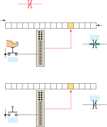
The symbol for the Examine If Open (XIO) instruction
is shown in Figure5-19 . The XIO instruction, which is
also called the Examine-off instruction, looks and oper-
ates like a normally closed relay contact. Associated with
each XIO instruction is a memory bit linked to the status
of an input device or an internal logical condition in a
rung. This instruction asks the PLC’s processor to exam-
ine if the contact is open. It does this by examining the
bit at the memory location speci ed by the address in the
following manner:
• As with any other input the memory bit is set to 1
or 0 depending on the status of the input (physical)
device or internal (logical) relay address associated
with that bit.
• A 1 corresponds to a true status or on condition.
• A 0 corresponds to a false status or off condition.
• When the Examine-off instruction is used to ex-
amine a physical input, then the instruction will be
interpreted as false when there is a physical input
(voltage) present (the bit is 1) and will be inter-
preted as true when there is no physical input pres-
ent (the bit is 0).
• If the Examine-off instruction were associated by
address with an internal relay, then the status of the
bit would be dependent on the logical status of the
internal bit with the same address as the instruction.
• Like the Examine-on instruction, the status of the
instruction (true or false) determines if the instruc-
tion will allow rung continuity through itself, like a
closed relay contact.
• The memory bit always follows the status (true = 1
or false = 0) of the input address or internal address
assigned to it. The interpretation of that bit, how-
ever, is determined by which instruction is used to
examine it.
• Examine-on instructions always interpret a 1 status
as true and a 0 status as false, while Examine-off in-
structions interpret a 1 status as false and a 0 status
as true.
The symbol for the Output Energize (OTE) instruc-
tion is shown in Figure5-20 . The OTE instruction looks
and operates like a relay coil and is associated with a
memory bit. This instruction signals the PLC to ener-
gize (switch on) or de-energize (switch off ) the output.
The processor makes this instruction true (analogous to
energizing a coil) when there is a logical path of true
XIC and XIO instructions in the rung. The operation of
the Output Energize instruction can be summarized as
follows:
• The status bit of the addressed Output Energize in-
struction is set to 1 to energize the output and to 0 to
de-energize the output.
• If a true logic path is established with the input
instructions in the rung, the OTE instruction is ener-
gized and the output device wired to its terminal is
energized.
• If a true logic path cannot be established or
rungconditions go false, the OTE instruction is
de-energized and the output device wired to it is
switched off.
Sometimes beginner programmers used to thinking in
terms of hardwired relay control circuits tend to use the
same type of contact (NO or NC) in the ladder logic pro-
gram that corresponds to the type of eld switch wired to
the discrete input. While this is true in many instances, it
is not the best way to think of the concept. A better ap-
proach is to separate the action of the eld device from
Figure 5-19 Examine If Open (XIO) instruction.
Symbol
Bit
number
Ι:1/4
Ι:1/4
Ι:1/4
Ι:1/4
15 14 13 12 11 10 9 8 7 6 5 4 3 2 1 0
15 14 13 12 11 10 9 8 7 6 5 4 3 2 1 0
1
0
Examine if open (XIO)
Examine-off
Status
Instruction interpreted
as false
Instruction interpreted
as true
pet10882_ch05_071-094.indd 82pet10882_ch05_071-094.indd 82 7/23/10 9:14 PM7/23/10 9:14 PM