Petruzella F.D. Programmable Logic Controllers
Подождите немного. Документ загружается.

43
Using PLCs requires us to become familiar with
other number systems besides decimal. Some
PLC models and individual PLC functions use
other numbering systems. This chapter deals
with some of these numbering systems, including
binary, octal, hexadecimal, BCD, Gray, and ASCII.
The basics of each system, as well as conversion
from one system to another, are explained.
Chapter Objectives
After completing this chapter, you will be able to:
3.1 De ne the decimal, binary, octal, and hexadecimal
numbering systems and be able to convert from one
numbering or coding system to another
3.2 Explain the BCD, Gray, and ASCII code systems
3.3 De ne the terms bit, byte, word, least signi cant bit
(LSB), and most signi cant bit (MSB) as they apply to
binary memory locations
3.4 Add, subtract, multiply, and divide binary numbers
3
Number Systems and Codes
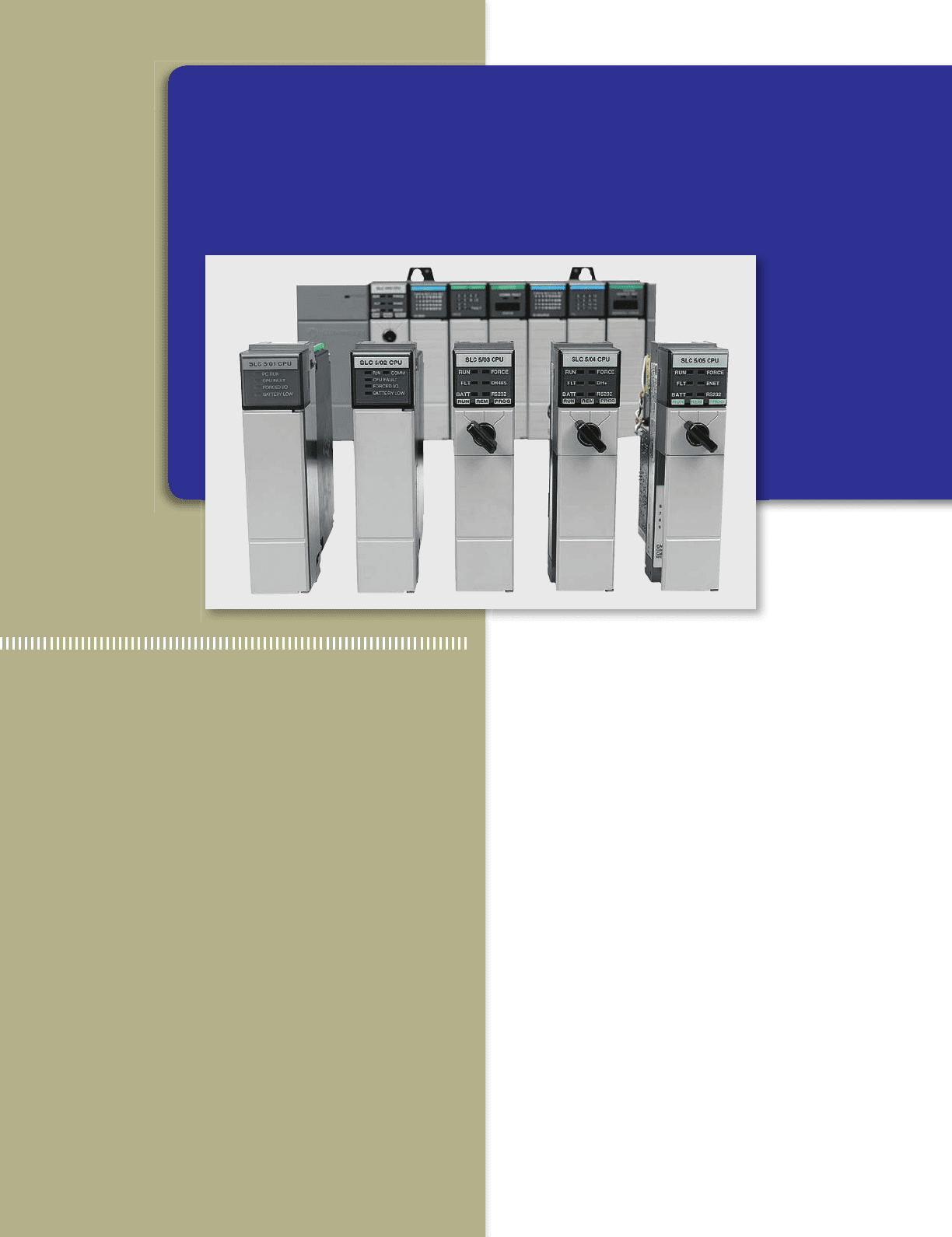
Image Used with Permission of Rockwell Automation, Inc.
pet10882_ch03_043-056.indd 43pet10882_ch03_043-056.indd 43 7/23/10 9:09 PM7/23/10 9:09 PM
44 Chapter 3 Number Systems and Codes
3.1 Decimal System
Knowledge of different number systems and digital codes
is quite useful when working with PLCs or with most any
type of digital computer. This is true because a basic re-
quirement of these devices is to represent, store, and oper-
ate on numbers. In general, PLCs work on binary numbers
in one form or another; these are used to represent various
codes or quantities.
The decimal system, which is most common to us, has a
base of 10. The radix or base of a number system determines
the total number of different symbols or digits used by that
system. For instance, in the decimal system, 10 unique num-
bers or digits—i.e., the digits 0 through 9—are used: the
total number of symbols is the same as the base, and the
symbol with the largest value is 1 less than the base.
The value of a decimal number depends on the dig-
its that make up the number and the place value of each
digit. A place (weight) value is assigned to each position
that a digit would hold from right to left. In the decimal
system the rst position, starting from the rightmost po-
sition, is 0; the second is 1; the third is 2; and so on up
to the last position. The weighted value of each position
can be expressed as the base (10 in this case) raised to
the power of the position. For the decimal system then,
the position weights are 1, 10, 100, 1000, and so on. Fig-
ure3-1 illustrates how the value of a decimal number can
be calculated by multiplying each digit by the weight of
its position and summing the results.
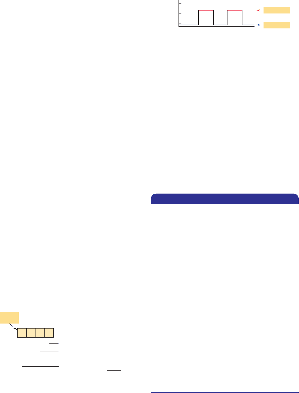
3.2 Binary System
The binary system uses the number 2 as the base. The
only allowable digits are 0 and 1. With digital circuits it is
easy to distinguish between two voltage levels (i.e., 15 V
and 0 V), which can be related to the binary digits 1 and 0
( Figure 3-2 ). Therefore the binary system can be applied
quite easily to PLCs and computer systems.
Since the binary system uses only two digits, each
position of a binary number can go through only two
changes, and then a 1 is carried to the immediate left po-
sition. Table 3-1 shows a comparison among four com-
mon number systems: decimal (base 10), octal (base 8),
hexadecimal (base 16), and binary (base 2). Note that all
numbering systems start at zero.
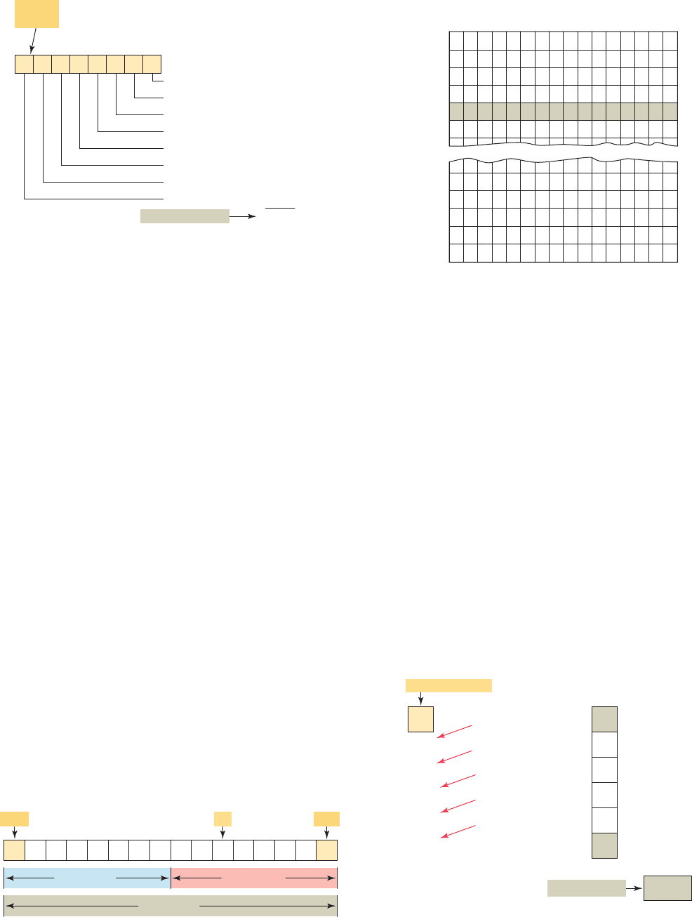
The decimal equivalent of a binary number can be de-
termined in a manner similar to that used for a decimal
number. This time the weighted values of the positions
are 1, 2, 4, 8, 16, 32, 64, and so on. The weighted value,
instead of being 10 raised to the power of the position, is
2 raised to the power of the position. Figure 3-3 illustrates
how the binary number 10101101 is converted to its deci-
mal equivalent: 173.
Each digit of a binary number is known as a bit. In a
PLC the processor-memory element consists of hundreds
or thousands of locations. These locations, or registers,
Decimal Octal Hexadecimal Binary
0 . . . . . . 0 . . . . . . . . 0 . . . . . . . . . . 0
1 . . . . . . 1 . . . . . . . . 1 . . . . . . . . . . 1
2 . . . . . . 2 . . . . . . . . 2 . . . . . . . . . . 10
3 . . . . . . 3 . . . . . . . . 3 . . . . . . . . . . 11
4 . . . . . . 4 . . . . . . . . 4 . . . . . . . . . 100
5 . . . . . . 5 . . . . . . . . 5 . . . . . . . . . 101
6 . . . . . . 6 . . . . . . . . 6 . . . . . . . . . 110
7 . . . . . . 7 . . . . . . . . 7 . . . . . . . . . 111
8 . . . . . . 10 . . . . . . . . 8 . . . . . . . . 1000
9 . . . . . . 11 . . . . . . . . 9 . . . . . . . . 1001
10 . . . . . . 12 . . . . . . . . A . . . . . . . . 1010
11 . . . . . . 13 . . . . . . . . B . . . . . . . . 1011
12 . . . . . . 14 . . . . . . . . C . . . . . . . . 1100
13 . . . . . . 15 . . . . . . . . D . . . . . . . . 1101
14 . . . . . . 16
. . . . . . . . E
. . . . . . . . 1110
15 . . . . . . 17 . . . . . . . . F . . . . . . . . 1111
16 . . . . . . 20 . . . . . . . . 10 . . . . . . . . 10000
17 . . . . . . 21 . . . . . . . . 11 . . . . . . . . 10001
18 . . . . . . 22 . . . . . . . . 12 . . . . . . . . 10010
19 . . . . . . 23 . . . . . . . . 13 . . . . . . . . 10011
20 . . . . . . 24 . . . . . . . . 14 . . . . . . . . 10100
Table 3-1 Number System Comparisons
Figure 3-1 Weighted value in the decimal system.
2196
0321
2
60
900
1000
1962
2 10
6 10
9 10
1 10
0
1
2
3
2 1
6 10
9 100
1 1000
10
(Sum of products)
Decimal
number
10
Figure 3-2 Digital signal waveform.
+5
0
Volts
Time
High (H) (1)
Low (L) (0)
pet10882_ch03_043-056.indd 44pet10882_ch03_043-056.indd 44 7/23/10 9:09 PM7/23/10 9:09 PM
Number Systems and Codes Chapter 3 45
are referred to as words. Each word is capable of storing
data in the form of binary digits, or bits. The number of
bits that a word can store depends on the type of PLC sys-
tem used. Sixteen-bit and 32-bit words are the most com-
mon. Bits can also be grouped within a word into bytes.
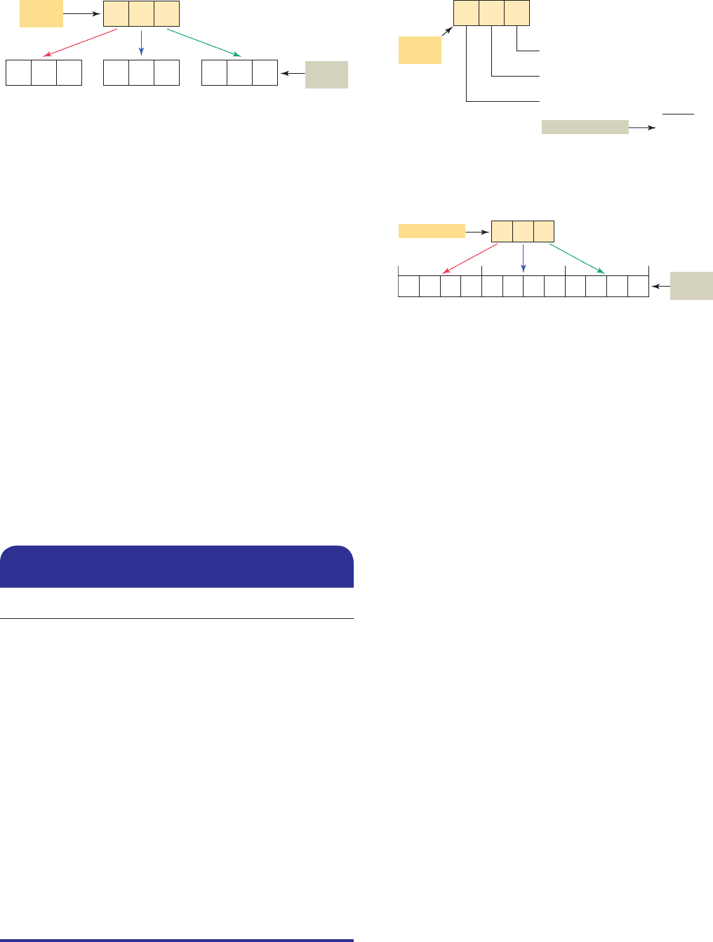
A group of 8 bits is a byte, and a group of 2 or more bytes
is a word. Figure 3-4 illustrates a 16-bit word made up
of 2 bytes. The least signi cant bit (LSB) is the digit that
represents the smallest value, and the most signi cant bit
(MSB) is the digit that represents the largest value. A bit
within the word can exist only in two states: a logical 1 (or
ON) condition, or a logical 0 (or OFF) condition.
PLC memory is organized using bytes, single words,
or double words. Older PLCs use 8-bit or 16-bit memory
words while newer systems, such as the ControlLogix
platform from Allen-Bradley, use 32-bit double words.
The size of the programmable controller memory relates
to the amount of user program that can be stored. If the
memory size is 1 K word ( Figure 3-5 ), it can store 1024
words or 16,384 (1024 3 16) bits of information using 16-
bit words, or 32,768 (1024 3 32) bits using 32-bit words.
To convert a decimal number to its binary equivalent,
we must perform a series of divisions by 2. Figure 3-6
illustrates the conversion of the decimal number 47 to bi-
nary. We start by dividing the decimal number by 2. If
there is a remainder, it is placed in the LSB of the binary
number. If there is no remainder, a 0 is placed in the LSB.
The result of the division is brought down and the pro-
cess is repeated until the result of successive divisions has
been reduced to 0.
Even though the binary system has only two digits, it
can be used to represent any quantity that can be repre-
sented in the decimal system. All PLCs work internally in
the binary system. The processor, being a digital device,
understands only 0s and 1s, or binary.
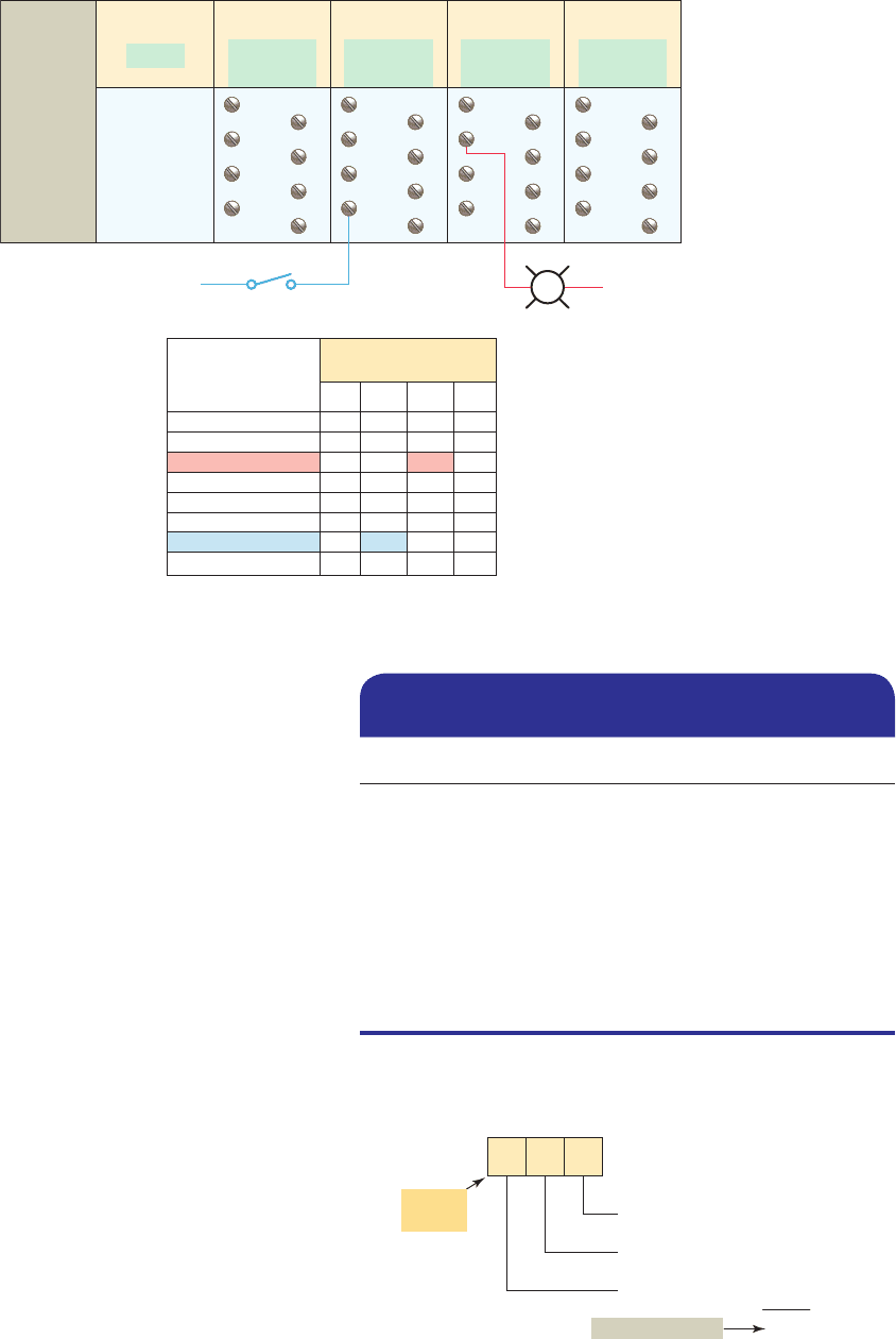
Computer memory is, then, a series of binary 1s and
0s. Figure 3-7 shows the output status le for an Allen-
Bradley SLC 500 modular chassis, which is made up of
single bits grouped into 16-bit words. One 16-bit output
le word is reserved for each slot in the chassis. Each bit
represents the ON or OFF state of one output point. These
points are numbered 0 through 15 across the top row from
Figure 3-3 Converting a binary number to a decimal
number.
1110
1
0
4
8
0
32
0
128
173
1 2
0
0 2
1
1 2
2
1 2
3
0 2
4
1 2
5
0 2
6
1 2
7
1 1
0 2
1 4
1 8
0 16
1 32
0 64
1 128
10
(Sum of products)
101
0
07
2
1
345
6
2
Decimal number
Binary
number
Figure 3-4 A 16-bit word.
16-bit word
Upper byte Lower byte
1
0
11001100011101
LSBBitMSB
Figure 3-5 1-K word memory.
0110011000111011
15
Bits
14
13 12 1110 9 8 7 6 5 4 3 2 1 0
0000
0001
0002
0003
0004
0005
1018
1019
1020
1021
1022
1023
Word
Addresses
Figure 3-6 Converting a decimal number to a binary
number.
1
1
1
1
0
1
2 = 23 with a remainder of
2 = 11 with a remainder of
2 =
5 with a remainder of
2 =
2 with a remainder of
2 =
1 with a remainder of
2 =
23
11
5
2
1
47 LSB
MSB
101111
with a remainder of
Decimal number
Binary number
pet10882_ch03_043-056.indd 45pet10882_ch03_043-056.indd 45 7/23/10 9:09 PM7/23/10 9:09 PM
46 Chapter 3 Number Systems and Codes
right to left. The column on the far right lists the output
module address. Although the table in Figure 3-7 illus-
trates sequentially addressed output status le words, in
reality a word is created in the table only if the processor
nds an output module residing in a particular slot. If the
slot is empty, no word will be created.
3.3 Negative Numbers
If a decimal number is positive, it has a plus sign; if a
number is negative, it has a minus sign. In binary number
systems, such as used in a PLC, it is not possible to use
positive and negative symbols to represent the polarity of
a number. One method of representing a binary number as
either a positive or negative value is to use an extra digit,
or sign bit, at the MSB side of the number. In the sign bit
position, a 0 indicates that the number is positive, and a
1indicates a negative number (Table 3-2).
Another method of expressing a negative number in
a digital system is by using the complement of a binary
number. To complement a binary number, change all the
1s to 0s and all the 0s to 1s. This is known as the 1’s
complement form of a binary number. For example, the
1’s complement of 1001 is 0110.
The most common way to express a negative binary
number is to show it as a 2’s complement number. The
2’s complement is the binary number that results when
1 is added to the 1’s complement. This system is shown
in Table 3-3. A zero sign bit means a positive number,
whereas a 1 sign bit means a negative number.
Using the 2’s complement makes it easier for the PLC
to perform mathematical operations. The correct sign bit
is generated by forming the 2’s complement. The PLC
knows that a number retrieved from memory is a nega-
tive number if the MSB is 1. Whenever a negative num-
ber is entered from a keyboard, the PLC stores it as a 2’s
complement. What follows is the original number in true
binary followed by its 1’s complement, its 2’s comple-
ment, and nally, its decimal equivalent.
Magnitude
Sign
Decimal
Value
Same as
binary
numbers
0111
. . . . . . . . 17
0110 . . . . . . . . 16
0101 . . . . . . . . 15
0100 . . . . . . . . 14
0011 . . . . . . . . 13
0010 . . . . . . . . 12
0001 . . . . . . . . 11
0000 . . . . . . . . 0
1001 . . . . . . . . 21
1010 . . . . . . . . 22
1011 . . . . . . . . 23
1100 . . . . . . . . 24
1101 . . . . . . . . 25
1110 . . . . . . . . 26
1111 . . . . . . . . 27
Table 3-2 Signed Binary Numbers
Signed
Decimal
1’s
Complement
2’s
Complement
17 . . . . . . . . . . 0111 . . . . . . . . . . . 0111
16 . . . . . . . . . . 0110 . . . . . . . . . . . 0110
15 . . . . . . . . . . 0101 . . . . . . . . . . . 0101
14 . . . . . . . . . . 0100 . . . . . . . . . . . 0100
13 . . . . . . . . . . 0011 . . . . . . . . . . . 0011
12 . . . . . . . . . . 0010 . . . . . . . . . . . 0010
11 . . . . . . . . . . 0001 . . . . . . . . . . . 0001
0 . . . . . . . . . . 0000 . . . . . . . . . . . 0000
21 . . . . . . . . . . 1110 . . . . . . . . . . . 1111
22 . . . . . . . . . . 1101 . . . . . . . . . . . 1110
23 . . . . . . . . . . 1100 . . . . . . . . . . . 1101
24 . . . . . . . . . . 1011 . . . . . . . . . . . 1100
25 . . . . . . . . . . 1010 . . . . . . . . . . . 1011
26 . . . . . . . . . . 1001 . . . . . . . . . . . 1010
27 . . . . . . . . . . 1000 . . . . . . . . . . . 1001
Table 3-3 1’s and 2’s Complement
Representation of Positive and Negative
Numbers
Same as
binary
numbers
Figure 3-7 SLC 500 output status fi le.
15
1
0
1
0
1
14
1
0
0
0
1
13
0
1
1
0
1
12
0
1
0
0
0
11
0
0
1
0
1
10
0
1
1
0
0
9
1
0
0
0
0
8
0
0
0
0
1
7
1
0
1
0
1
6
1
0
1
1
1
5
1
0
1
0
0
4
1
0
0
0
0
3
0
1
0
1
1
2
0
1
0
0
1
1
0
1
0
0
0
0
1
1
1
0
1
Address
O:1
O:2
O:3
O:4
O:5
pet10882_ch03_043-056.indd 46pet10882_ch03_043-056.indd 46 7/23/10 9:09 PM7/23/10 9:09 PM
Number Systems and Codes Chapter 3 47
3.4 Octal System
To express the number in the binary system requires
many more digits than in the decimal system. Too many
binary digits can become cumbersome to read or write.
To solve this problem, other related numbering systems
are used.
The octal numbering system, a base 8 system, is used
because 8 data bits make up a byte of information that
can be addressed. Figure 3-8 illustrates the addressing of
I/O modules using the octal numbering system. The digits
range from 0 to 7; therefore, numbers 8 and 9 are not al-
lowed. Allen-Bradley PLC-5 processors use octal-based
I/O addressing while the SLC 500 and Logix controllers
use decimal-base 10 addressing.
Octal is a convenient means of handling large binary
numbers. As shown in Table 3-4, one octal digit can be
used to express three binary digits. As in all other number-
ing systems, each digit in an octal number has a weighted
decimal value according to its position. Figure 3-9 illus-
trates how the octal number 462 is converted to its deci-
mal equivalent: 306.
Octal converts easily to binary equivalents. For ex-
ample, the octal number 462 is converted to its binary
equivalent by assembling the 3-bit groups, as illustrated
in Figure 3-10 . Notice the simplicity of the notation: the
octal 462 is much easier to read and write than its binary
equivalent is.
Binary Octal
000 . . . . . . . . 0
001 . . . . . . . . 1
010 . . . . . . . . 2
011 . . . . . . . . 3
100 . . . . . . . . 4
101 . . . . . . . . 5
110 . . . . . . . . 6
111 . . . . . . . . 7
Table 3-4 Binary and Related Octal
Code
Figure 3-8 Addressing of I/O modules using the octal numbering system.
I/O module screw
terminal number
0
1
2
3
4
5
6
7
12 3 4
0102030
1112131
2122232
3132333
4142434
5152535
6162636
7172737
Slot number
and address
Power
supply
Slot 0 Slot 1 Slot 2 Slot 3 Slot 4
CPU
Address
0–7
Address
10–17
Address
20–27
Address
30–37
0
2
4
6
1
3
5
7
O:3/22
I:2/16
0
2
4
6
1
3
5
7
0
2
4
6
1
3
5
7
0
2
4
6
1
3
5
7
Figure 3-9 Converting an octal number to a decimal
number.
246
2
48
256
306
2 8
0
6 8
1
4 8
2
2 1
6 8
4 64
8
(Sum of products)
Decimal number
10
Octal
number
pet10882_ch03_043-056.indd 47pet10882_ch03_043-056.indd 47 7/23/10 9:09 PM7/23/10 9:09 PM
48 Chapter 3 Number Systems and Codes
3.5 Hexadecimal System
The hexadecimal (hex) numbering system is used in pro-
grammable controllers because a word of data consists of
16 data bits, or two 8-bit bytes. The hexadecimal system
is a base 16 system, with A to F used to represent decimal
numbers 10 to 15 (Table 3-5). The hexadecimal number-
ing system allows the status of a large number of binary
bits to be represented in a small space, such as on a com-
puter screen or PLC programming device display.
The techniques used when converting hexadecimal to
decimal and decimal to hexadecimal are the same as those
used for binary and octal. To convert a hexadecimal num-
ber to its decimal equivalent, the hexadecimal digits in the
columns are multiplied by the base 16 weight, depending
on digit signi cance. Figure 3-11 illustrates how the con-
version would be done for the hex number 1B7.
Hexadecimal numbers can easily be converted to bi-
nary numbers. Conversion is accomplished by writing the
4-bit binary equivalent of the hex digit for each position,
as illustrated in Figure 3-12 .
3.6 Binary Coded Decimal (BCD)
System
The binary coded decimal (BCD) system provides a con-
venient way of handling large numbers that need to be
input to or output from a PLC. As you can see from look-
ing at the various number systems, there is no easy way
to go from binary to decimal and back. The BCD system
provides a means of converting a code readily handled
by humans (decimal) to a code readily handled by the
equipment (binary). PLC thumbwheel switches and LED
displays are examples of PLC devices that make use of
the BCD number system. Table 3-6 shows examples of
numeric values in decimal, binary, BCD, and hexadeci-
mal representation.
The BCD system uses 4 bits to represent each decimal
digit. The 4 bits used are the binary equivalents of the
numbers from 0 to 9. In the BCD system, the largest deci-
mal number that can be displayed by any four digits is 9.
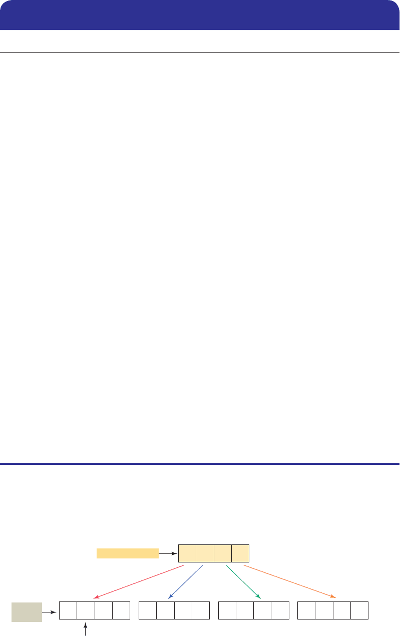
The BCD representation of a decimal number is ob-
tained by replacing each decimal digit by its BCD equiva-
lent. To distinguish the BCD numbering system from a
binary system, a BCD designation is placed to the right
of the units digit. The BCD representation of the decimal
number 7863 is shown in Figure 3-13 .
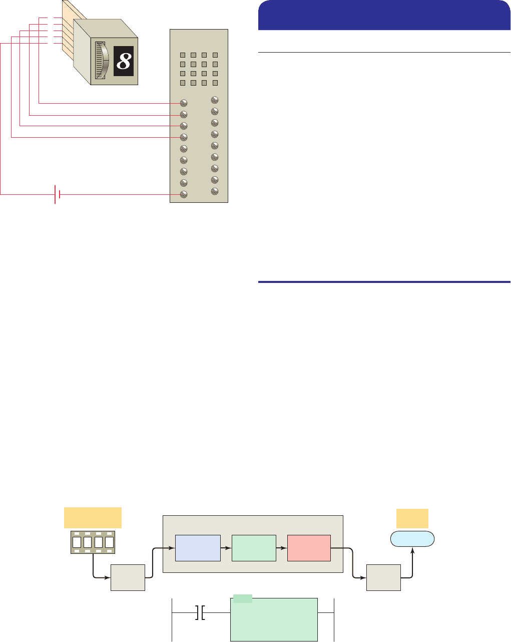
A thumbwheel switch is one example of an input de-
vice that uses BCD. Figure 3-14 shows a single-digit
BCD thumbwheel. The circuit board attached to the
thumbwheel has one connection for each bit’s weight plus
Hexadecimal Binary Decimal
0 . . . . . . . . . . . . . 0000 . . . . . . . . . . . 0
1 . . . . . . . . . . . . . 0001 . . . . . . . . . . . 1
2 . . . . . . . . . . . . . 0010 . . . . . . . . . . . 2
3 . . . . . . . . . . . . . 0011 . . . . . . . . . . . 3
4 . . . . . . . . . . . . . 0100 . . . . . . . . . . . 4
5 . . . . . . . . . . . . . 0101 . . . . . . . . . . . 5
6 . . . . . . . . . . . . . 0110 . . . . . . . . . . . 6
7 . . . . . . . . . . . . . 0111 . . . . . . . . . . . 7
8 . . . . . . . . . . . . . 1000 . . . . . . . . . . . 8
9 . . . . . . . . . . . . . 1001 . . . . . . . . . . . 9
A . . . . . . . . . . . . . 1010 . . . . . . . . . . 10
B . . . . . . . . . . . . . 1011 . . . . . . . . . . 11
C . . . . . . . . . . . . . 1100 . . . . . . . . . . 12
D . . . . . . . . . . . . . 1101 . . . . . . . . . . 13
E . . . . . . . . . . . . . 1110 . . . . . . . . . . 14
F . . . . . . . . . . . . . 1111 . . . . . . . . . . 15
Table 3-5 Hexadecimal Numbering
System
Figure 3-11 Converting a hexadecimal number to a
decimal number.
71
B
7
176
256
439
7 16
0
11 16
1
1 16
2
7 1
11 16
1 256
(Sum of products)
Decimal number
10
Hex
number
Figure 3-12 Converting a hexadecimal number to a binary
number.
101
71 B
100 110
Hex number
0 1 1
Binary
number
Figure 3-10 Converting an octal number to a binary
number.
001
24 6
010 011
Binary
n
umber
Octal
number
pet10882_ch03_043-056.indd 48pet10882_ch03_043-056.indd 48 7/23/10 9:09 PM7/23/10 9:09 PM
Number Systems and Codes Chapter 3 49
a common connection. The operator dials in a decimal
digit between 0 and 9, and the thumbwheel switch outputs
the equivalent 4 bits of BCD data. In this example, the
number eight is dialed to produce the input bit pattern of
1000. A four-digit thumbwheel switch, similar to the one
shown, would control a total of 16 (4 3 4) PLC inputs.
Scienti c calculators are available to convert num-
bers back and forth between decimal, binary, octal, and
Figure 3-13 The BCD representation of a decimal number.
37 8
10
0
4 bits used for
each decimal digit
10 1
0
0 10
6
11 0 1
0
1
BCD
BCD
number
Decimal number
Decimal Binary BCD Hexadecimal
0 . . . . . . . . . . . . . . . 0 . . . . . . . . . . . . . 0000 . . . . . . . . . . . . 0
1 . . . . . . . . . . . . . . . 1 . . . . . . . . . . . . . 0001 . . . . . . . . . . . . 1
2 . . . . . . . . . . . . . . . 10 . . . . . . . . . . . . . 0010 . . . . . . . . . . . . 2
3 . . . . . . . . . . . . . . . 11 . . . . . . . . . . . . . 0011 . . . . . . . . . . . . 3
4 . . . . . . . . . . . . . . 100 . . . . . . . . . . . . . 0100 . . . . . . . . . . . . 4
5 . . . . . . . . . . . . . . 101 . . . . . . . . . . . . . 0101 . . . . . . . . . . . . 5
6 . . . . . . . . . . . . . . 110 . . . . . . . . . . . . . 0110 . . . . . . . . . . . . 6
7 . . . . . . . . . . . . . . 111 . . . . . . . . . . . . . 0111 . . . . . . . . . . . . 7
8 . . . . . . . . . . . . . 1000 . . . . . . . . . . . . . 1000 . . . . . . . . . . . . 8
9 . . . . . . . . . . . . . 1001 . . . . . . . . . . . . . 1001 . . . . . . . . . . . . 9
10 . . . . . . . . . . . . . 1010 . . . . . . . . . . 0001 0000 . . . . . . . . . . . . A
11 . . . . . . . . . . . . . 1011 . . . . . . . . . . 0001 0001 . . . . . . . . . . . . B
12 . . . . . . . . . . . . . 1100 . . . . . . . . . . 0001 0010 . . . . . . . . . . . . C
13 . . . . . . . . . . . . . 1101 . . . . . . . . . . 0001 0011 . . . . . . . . . . . . D
14 . . . . . . . . . . . . . 1110 . . . . . . . . . . 0001 0100
. . . . . . . . . . . . E
15 . . . . . . . . . . . . . 1111 . . . . . . . . . . 0001 0101 . . . . . . . . . . . . F
16 . . . . . . . . . . . . 1 0000 . . . . . . . . . . 0001 0110 . . . . . . . . . . . . 10
17 . . . . . . . . . . . . 1 0001 . . . . . . . . . . 0001 0111 . . . . . . . . . . . . 11
18 . . . . . . . . . . . . 1 0010 . . . . . . . . . . 0001 1000 . . . . . . . . . . . . 12
19 . . . . . . . . . . . . 1 0011 . . . . . . . . . . 0001 1001 . . . . . . . . . . . . 13
20 . . . . . . . . . . . . 1 0100 . . . . . . . . . . 0010 0000 . . . . . . . . . . . . 14
126 . . . . . . . . . . . 111 1110 . . . . . . . 0001 0010 0110 . . . . . . . . . . . . 7E
127 . . . . . . . . . . . 111 1111 . . . . . . . 0001 0010 0111 . . . . . . . . . . . . 7F
128 . . . . . . . . . . 1000 0000 . . . . . . . 0001 0010 1000 . . . . . . . . . . . . 80
510 . . . . . . . . . 1 1111 1110 . . . . . . . 0101 0001 0000 . . . . . . . . . . . 1FE
511 . . . . . . . . . 1 1111 1111 . . . . . . . 0101 0001 0001 . . . . . . . . . . . 1FF
512 . . . . . . . . . 10 0000 0000 . . . . . . . 0101 0001 0010 . . . . . . . . . . . 200
Table 3-6 Numeric Values in Decimal, Binary, BCD,
and Hexadecimal Representation
pet10882_ch03_043-056.indd 49pet10882_ch03_043-056.indd 49 7/23/10 9:09 PM7/23/10 9:09 PM
50 Chapter 3 Number Systems and Codes
Gray Code Binary
0000 . . . . . . . . . . 0000
0001 . . . . . . . . . . 0001
0011 . . . . . . . . . . 0010
0010 . . . . . . . . . . 0011
0110 . . . . . . . . . . 0100
0111 . . . . . . . . . . 0101
0101 . . . . . . . . . . 0110
0100 . . . . . . . . . . 0111
1100 . . . . . . . . . . 1000
1101 . . . . . . . . . . 1001
1111 . . . . . . . . . . 1010
1110 . . . . . . . . . . 1011
1010 . . . . . . . . . . 1100
1011 . . . . . . . . . . 1101
1001 . . . . . . . . . . 1110
1000 . . . . . . . . . . 1111
Table 3-7 Gray Code and Binary
Equivalent
Figure 3-15 PLC number conversion.
Thumbwheel or
other input
Input
module
BCD
to binary
PLC
Processor
Binary
to BCD
Decimal
readout
1765
Output
module
Convert-to-decimal PLC instruction
Destination
N7:23
O:20
TOD
To BCD
Source
Input A
4196
Figure 3-14 BCD thumbwheel switch interfaced to a PLC.
1
2
4
8
C
1s Input = 0
2s Input = 0
4s Input = 0
8s Input = 1
+–
Input
module
hexadecimal. In addition, PLCs contain number conver-
sion functions such as illustrated in Figure 3-15 . BCD-
to-binary conversion is required for the input while
binary-to-BCD conversion is required for the output. The
PLC convert-to-decimal instruction will convert the bi-
nary bit pattern at the source address, N7:23, into a BCD
bit pattern of the same decimal value as the destination
address, O:20. The instruction executes every time it is
scanned, and the instruction is true.
Many PLCs allow you to change the format of the data
that the data monitor displays. For example, the change
radix function found on Allen-Bradley controllers allows
you to change the display format of data to binary, octal,
decimal, hexadecimal, or ASCII.
3.7 Gray Code
The Gray code is a special type of binary code that does
not use position weighting. In other words, each position
does not have a de nite weight. The Gray code is set up
so that as we progress from one number to the next, only
one bit changes. This can be quite confusing for count-
ing circuits, but it is ideal for encoder circuits. For ex-
ample, absolute encoders are position transducers that use
the Gray code to determine angular position. The Gray
code has the advantage that for each “count” (each transi-
tion from one number to the next) only one digit changes.
Table 3-7 shows the Gray code and the binary equivalent
for comparison.
In binary, as many as four digits could change for a single
“count.” For example, the transition from binary 0111 to
1000 (decimal 7 to 8) involves a change in all four digits.
This kind of change increases the possibility for error in cer-
tain digital circuits. For this reason, the Gray code is consid-
ered to be an error-minimizing code. Because only one bit
pet10882_ch03_043-056.indd 50pet10882_ch03_043-056.indd 50 7/23/10 9:09 PM7/23/10 9:09 PM
Number Systems and Codes Chapter 3 51
changes at a time, the speed of transition for the Gray code is
considerably faster than that for codes such as BCD.
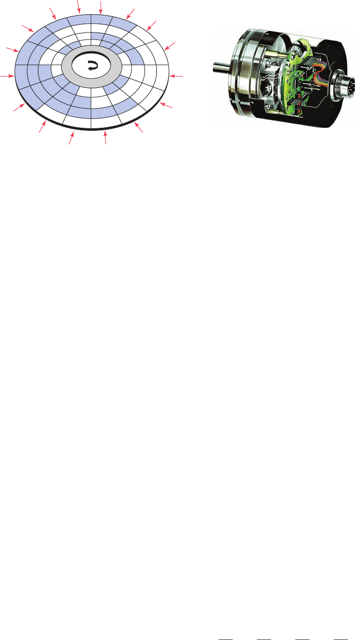
Gray codes are used with position encoders for accu-
rate control of the motion of robots, machine tools, and
servomechanisms. Figure 3-16 shows an optical encoder
disk that uses a 4-bit Gray code to detect changes in angu-
lar position. In this example, the encoder disk is attached
to a rotating shaft and outputs a digital Gray code signal
that is used to determine the position of the shaft. A xed
array of photo diodes senses the re ected light from each
of the cells across a row of the encoder path. Depending
on the amount of light re ected, each cell will output a
voltage corresponding to a binary 1 or 0. Thus, a different
4-bit word is generated for each row of the disk.
3.8 ASCII Code
ASCII stands for American Standard Code for Informa-
tion Interchange. It is an alphanumeric code because it in-
cludes letters as well as numbers. The characters accessed
by the ASCII code include 10 numeric digits; 26lower-
case and 26 uppercase letters of the alphabet; and about
25 special characters, including those found on a standard
typewriter. Table 3-8 shows a partial listing of the ASCII
code. It is used to interface the PLC CPU with alphanu-
meric keyboards and printers.
The keystrokes on the keyboard of a computer are con-
verted directly into ASCII for processing by the computer.
Each time you press a key on a computer keyboard, a 7-or
8-bit word is stored in computer memory to represent the
alphanumeric, function, or control data represented by the
speci c keyboard key that was depressed. ASCII input
modules convert ASCII code input information from
an external device to alphanumeric information that the
PLC can process. The communication interfacing is done
through either an RS-232 or RS-422 protocol. Modules
are available that will transmit and receive ASCII les and
that can be used to create an operator interface. The user
writes a program in the BASIC language that operates in
conjunction with the ladder logic as the program runs.
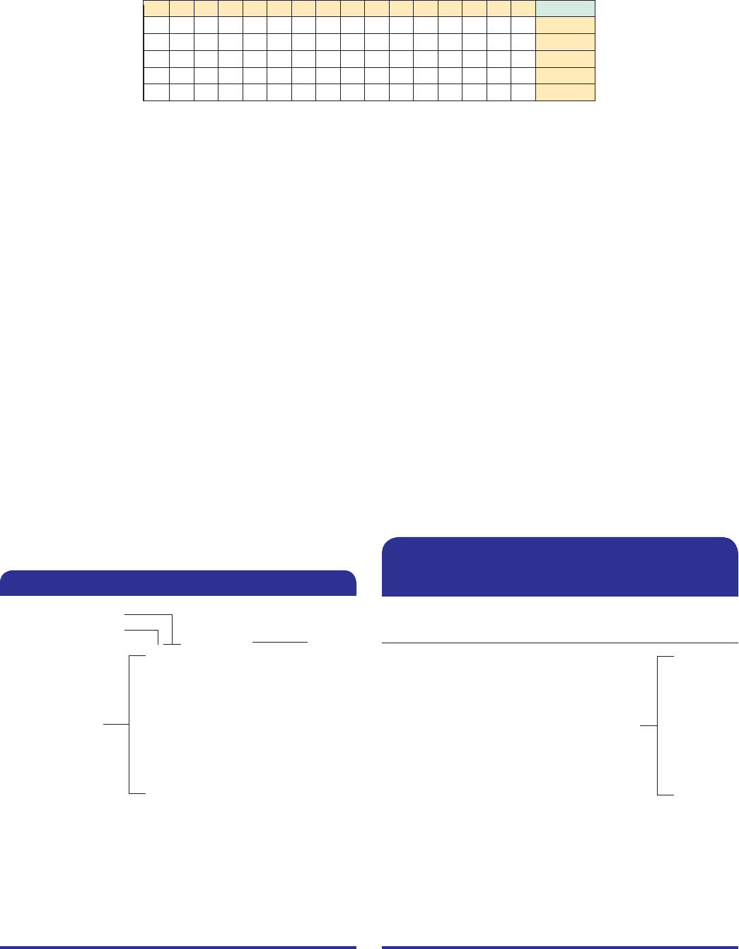
3.9 Parity Bit
Some PLC communication systems use a binary digit to
check the accuracy of data transmission. For example,
when data are transferred between PLCs, one of the bi-
nary digits may be accidentally changed from a 1 to a 0.
This can happen because of a transient or a noise or be-
cause of a failure in some portion of the transmission net-
work. A parity bit is used to detect errors that may occur
while a word is moved.
Parity is a system in which each character transmitted
contains one additional bit. That bit is known as a par-
ity bit. The bit may be a binary 0 or binary 1, depend-
ing on the number of 1s and 0s in the character itself.
Two systems of parity are normally used: odd and even.
Odd parity means that the total number of binary 1 bits in
the character, including the parity bit, is odd. Even parity
means that the number of binary 1 bits in the character, in-
cluding the parity bit, is even. Examples of odd and even
parity are shown in Table 3-9.
3.10 Binary Arithmetic
Arithmetic circuit units form a part of the CPU. Mathe-
matical operations include addition, subtraction, multipli-
cation, and division. Binary addition follows rules similar
to decimal addition. When adding with binary numbers,
there are only four conditions that can occur:
0101
10 10 11 11
0 1 1 0 carry 1
Figure 3-16 Optical encoder disk.
Source: Photo courtesy Baumer Electric.
0111
0110
0101
0100
1100
1101
1111
1110
1010
1011
1001
1000
0000
0001
0011
0010
1
1
1
0
pet10882_ch03_043-056.indd 51pet10882_ch03_043-056.indd 51 7/23/10 9:09 PM7/23/10 9:09 PM

52 Chapter 3 Number Systems and Codes
larger binary numbers, the resulting 1s are carried
into higher-order columns, as shown in the following
examples.
Decimal Equivalent binary
5 101
12 1 10
7 111
10 10 10
1 3 1 11
13 11 01
26 1 1010
112 1 1100
38 1 0 0110
In arithmetic functions, the initial numeric quantities
that are to be combined by subtraction are the minuend
carry
1
carry
1
carry
1
Character 7-Bit ASCII Character 7-Bit ASCII
A . . . . . . . . . . 100 0001 X . . . . . . . . . . 101 1000
B . . . . . . . . . . 100 0010 Y . . . . . . . . . . 101 1001
C . . . . . . . . . . 100 0011 Z . . . . . . . . . . 101 1010
D . . . . . . . . . . 100 0100 0 . . . . . . . . . . 011 0000
E . . . . . . . . . . 100 0101 1 . . . . . . . . . . 011 0001
F . . . . . . . . . . 100 0110 2 . . . . . . . . . . 011 0010
G . . . . . . . . . . 100 0111 3 . . . . . . . . . . 011 0011
H . . . . . . . . . . 100 1000 4 . . . . . . . . . . 011 0100
I . . . . . . . . . . 100 1001 5 . . . . . . . . . . 011 0101
J . . . . . . . . . . 100 1010 6 . . . . . . . . . . 011 0110
K . . . . . . . . . . 100 1011 7 . . . . . . . . . . 011 0111
L . . . . . . . . . . 100 1100 8 . . . . . . . . . . 011 1000
M . . . . . . . . . . 100 1101 9 . . . . . . . . . . 011 1001
N . . . . . . . . . . 100 1110 blank . . . . . . . . . 010 0000
O . . . . . . . . . . 100 1111 . . . . . . . . . . . 010 1110
P . . . . . . . . . . 101 0000 , . . . . . . . . . . 010 1100
Q . . . . . . . . . . 101 0001 1 . . . . . . . . . . 010 1011
R . . . . . . . . . . 101 0010 2 . . . . . . . . . . 010 1101
S . . . . . . . . . . 101 0011 # . . . . . . . . . . 010 0011
T . . . . . . . . . . 101 0100
( . . . . . . . . . . 010 1000
U . . . . . . . . . . 101 0101 % . . . . . . . . . . 010 0101
V . . . . . . . . . . 101 0110 5 . . . . . . . . . . 011 1101
W . . . . . . . . . . 101 0111
Table 3-8 Partial Listing of ASCII Code
Character
Even
Parity Bit
Odd
Parity Bit
0000 . . . . . . . . . . 0 . . . . . . . . . . . 1
0001 . . . . . . . . . . 1 . . . . . . . . . . . 0
0010 . . . . . . . . . . 1 . . . . . . . . . . . 0
0011 . . . . . . . . . . 0 . . . . . . . . . . . 1
0100 . . . . . . . . . . 1 . . . . . . . . . . . 0
0101 . . . . . . . . . . 0 . . . . . . . . . . . 1
0110 . . . . . . . . . . 0 . . . . . . . . . . . 1
0111 . . . . . . . . . . 1 . . . . . . . . . . . 0
1000 . . . . . . . . . . 1 . . . . . . . . . . . 0
1001 . . . . . . . . . . 0 . . . . . . . . . . . 1
Table 3-9 Odd and Even Parity
The rst three conditions are easy because they are
like adding decimals, but the last condition is slightly
different. In decimal, 1 1 1 5 2. In binary, a 2 is writ-
ten 10. Therefore, in binary, 1 1 1 5 0, with a carry of
1 to the next most signi cant place value. When adding
pet10882_ch03_043-056.indd 52pet10882_ch03_043-056.indd 52 7/23/10 9:09 PM7/23/10 9:09 PM