Petruzella F.D. Programmable Logic Controllers
Подождите немного. Документ загружается.

PLC Hardware Components Chapter 2 33
ELECTRICAL ISOLATION
Recall that I/O module circuitry is electrically isolated to
protect the low-level internal circuitry of the PLC from
high voltages that can be encountered from eld device
connections. The speci cation for electrical isolation,
typically 1500 or 2500 volts AC, rates the module’s ca-
pacity for sustaining an excessive voltage at its input or
output terminals. Although this isolation protects the
logic side of the module from excessive input or output
voltages or current, the power circuitry of the module may
be damaged.
POINTS PER MODULE
This speci cation de nes the number of eld inputs or
outputs that can be connected to a single module. Most
commonly, a discrete module will have 8, 16, or 32 cir-
cuits; however, low-end controllers may have only 2 or
4circuits. Modules with 32 or 64 input or output bits are
referred to as high-density modules. Some modules pro-
vide more than one common terminal, which allows the
user to use different voltage ranges on the same card as
well as to distribute the current more effectively.
BACKPLANE CURRENT DRAW
This value indicates the amount of current the module
requires from the backplane. The sum of the backplane
current drawn for all modules in a chassis is used to select
the appropriate chassis power supply rating.
Typical Analog I/O Module
Specifi cations
CHANNELS PER MODULE
Whereas individual circuits on discrete I/O modules are
referred to as points, circuits on analog I/O modules are
often referred to as channels. These modules normally have
4, 8, or 16 channels. Analog modules may allow for either
single-ended or differential connections. Single-ended
connections use a single ground terminal for all channels
or for groups of channels. Differential connections use a
separate positive and negative terminal for each channel.
If the module normally allows 16 single-ended connec-
tions, it will generally allow only 8 differential connec-
tions. Single-ended connections are more susceptible to
electrical noise.
INPUT CURRENT/VOLTAGE RANGE(S)
These are the voltage or current signal ranges that an ana-
log input module is designed to accept. The input ranges
must be matched accordingly to the varying current or
voltage signals generated by the analog sensors.
OUTPUT CURRENT/VOLTAGE RANGE(S)
This speci cation de nes the current or voltage signal
ranges that a particular analog output module is designed
to output under program control. The output ranges must
be matched according to the varying voltage or current
signals that will be required to drive the analog output
devices.
INPUT PROTECTION
Analog input circuits are usually protected against acci-
dentally connecting a voltage that exceeds the speci ed
input voltage range.
RESOLUTION
The resolution of an analog I/O module speci es how ac-
curately an analog value can be represented digitally. This
speci cation determines the smallest measurable unit of
current or voltage. The higher the resolution (typically
speci ed in bits), the more accurately an analog value can
be represented.
INPUT IMPEDANCE AND CAPACITANCE
For analog I/Os, these values must be matched to the ex-
ternal device connected to the module. Typical ratings are
in Megohm (MV) and picofarads (pF).
COMMON-MODE REJECTION
Noise is generally caused by electromagnetic interfer-
ence, radio frequency interference, and ground loops.
Common-mode noise rejection applies only to differ-
ential inputs and refers to an analog module’s ability to
prevent noise from interfering with data integrity on a
single channel and from channel to channel on the mod-
ule. Noise that is picked up equally in parallel wires is
rejected because the difference is zero. Twisted pair wires
are used to ensure that this type of noise is equal on both
wires. Common-mode rejection is normally expressed in
decibels or as a ratio.
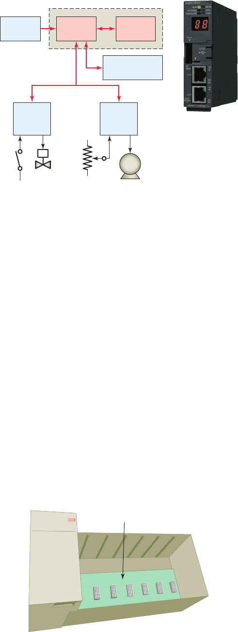
2.6 The Central Processing
Unit (CPU)
The central processing unit (CPU) is built into single-
unit xed PLCs while modular rack types typically use
a plug-in module. CPU, controller, and processor are all
terms used by different manufacturers to denote the same
module that performs basically the same functions. Pro-
cessors vary in processing speed and memory options. A
processor module can be divided into two sections: the
CPU section and the memory section ( Figure2-36 ). The
CPU section executes the program and makes the deci-
sions needed by the PLC to operate and communicate
pet10882_ch02_017-042.indd 33pet10882_ch02_017-042.indd 33 7/23/10 9:06 PM7/23/10 9:06 PM
34 Chapter 2 PLC Hardware Components
with other modules. The memory section electronically
stores the PLC program along with other retrievable digi-
tal information.
The PLC power supply provides the necessary power
(typically 5 VDC) to the processor and I/O modules
plugged into the backplane of the rack ( Figure 2-37 ).
Power supplies are available for most voltage sources
encountered. The power supply converts 115 VAC or
230VAC into the usable DC voltage required by the CPU,
memory, and I/O electronic circuitry. PLC power supplies
are normally designed to withstand momentary losses of
power without affecting the operation of the PLC. Hold-
up time , which is the length of time a PLC can tolerate
a power loss, typically ranges from 10 milliseconds to
3seconds.
The CPU contains the similar type of microproces-
sor found in a personal computer. The difference is that
the program used with the microprocessor is designed to
facilitate industrial control rather than provide general-
purpose computing. The CPU executes the operating
system, manages memory, monitors inputs, evaluates the
user logic (ladder program), and turns on the appropriate
outputs.
The CPU of a PLC system may contain more than one
processor. One advantage of using multiprocessing is that
the overall operating speed is improved. Each processor
has its own memory and programs, which operate simul-
taneously and independently. In such con gurations the
scan of each processor is parallel and independent thus
reducing the total response time. Fault-tolerant PLC sys-
tems support dual processors for critical processes. These
systems allow the user to con gure the system with redun-
dant (two) processors, which allows transfer of control to
the second processor in the event of a processor fault.
Associated with the processor unit will be a number of
status LED indicators to provide system diagnostic infor-
mation to the operator ( Figure2-38 ). Also, a keyswitch
may be provided that allows you to select one of the fol-
lowing three modes of operation: RUN, PROG, and REM.
RUN Position
• Places the processor in the Run mode
• Executes the ladder program and energizes output
devices
• Prevents you from performing online program edit-
ing in this position
• Prevents you from using a programmer/operator in-
terface device to change the processor mode
PROG Position
• Places the processor in the Program mode
• Prevents the processor from scanning or executing
the ladder program, and the controller outputs are
de-energized
• Allows you to perform program entry and editing
• Prevents you from using a programmer/operator in-
terface device to change the processor mode
REM Position
• Places the processor in the Remote mode: either the
REMote Run, REMote Program, or REMote Test
mode
• Allows you to change the processor mode from a
programmer/operator interface device
• Allows you to perform online program editing
The processor module also contains circuitry to com-
municate with the programming device. Somewhere on
the module you will nd a connector that allows the PLC
to be connected to an external programming device. The
decision-making capabilities of PLC processors go far
beyond simple logic processing. The processor performs
Figure 2-36 Sections of a PLC processor module.
Source: Courtesy Mitsubishi Automation.
Communication
interface
Processor module
Discrete
I/O
devices
Analog
I/O
devices
I/O modules
MemoryCPU
Power
supply
Figure 2-37 PLC power supply.
Backplane
Power
Power
supply
pet10882_ch02_017-042.indd 34pet10882_ch02_017-042.indd 34 7/23/10 9:06 PM7/23/10 9:06 PM

PLC Hardware Components Chapter 2 35
other functions such as timing, counting, latching, com-
paring, motion control and complex math functions.
PLC processors have changed constantly due to ad-
vancements in computer technology and greater demand
from applications. Today, processors are faster and have
additional instructions added as new models are intro-
duced. Because PLCs are microprocessor based, they can
be made to perform tasks that a computer can do. In ad-
dition to their control functions, PLCs can be networked
to do supervisory control and data acquisition (SCADA).
Many electronic components found in processors and
other types of PLC modules are sensitive to electrostatic
voltages that can degrade their performance or damage
them. The following static control procedures should be
followed when handling and working with static-sensitive
devices and modules:
• Ground yourself by touching a conductive surface
before handling static-sensitive components.
• Wear a wrist strap that provides a path to bleed off
any charge that may build up during work.
• Be careful not to touch the backplane connector or
connector pins of the PLC system (always handle
the circuit cards by the edge if possible).
• Be careful not to touch other circuit components in
a module when you con gure or replace its internal
components.
• When not in use, store modules in its static-shield bag.
• If available, use a static-safe work station.
2.7 Memory Design
Memory is the element that stores information, programs,
and data in a PLC. The user memory of a PLC includes
space for the user program as well as addressable memory
locations for storage of data. Data are stored in memory
locations by a process called writing. Data are retrieved
from memory by what is referred to as reading .
The complexity of the program determines the amount
of memory required. Memory elements store individual
pieces of information called bits (for binary digits ). The
amount of memory capacity is speci ed in increments of
1000 or in “K” increments, where 1 K is 1024 bytes of
memory storage (a byte is 8 bits).
The program is stored in the memory as 1s and 0s,
which are typically assembled in the form of 16-bit
words. Memory sizes are commonly expressed in thou-
sands of words that can be stored in the system; thus 2K
is a memory of 2000 words, and 64 K is a memory of
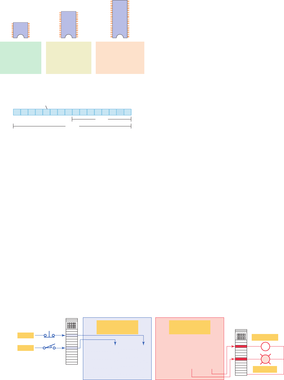
64,000 words. The memory size varies from as small as
1K for small systems to 32 MB for very large systems
( Figure2-39 ). Memory capacity is an important prereq-
uisite for determining whether a particular processor will
handle the requirements of the speci c application.
Memory location refers to an address in the CPU’s
memory where a binary word can be stored. A word usu-
ally consists of 16 bits. Each binary piece of data is a bit
and eight bits make up one byte ( Figure2-40 ). Memory
utilization refers to the number of memory locations re-
quired to store each type of instruction. A rule of thumb
Figure 2-38 Typical processor module.
Keyswitch
Memory
module
Hardware
address
Battery (battery provides
backup power for the
CMOS RAM)
FORCE
SLC 5/05 CPU
Front viewSide view
RUN
ENETFLT
RS232BATT
PROGRUN REM
Channel 0
RS232
(DH485, DF1,
or ASCII)
Channel 1
ethernet
(10Base-T)
pet10882_ch02_017-042.indd 35pet10882_ch02_017-042.indd 35 7/23/10 9:06 PM7/23/10 9:06 PM
36 Chapter 2 PLC Hardware Components
for memory locations is one location per coil or contact.
One K of memory would then allow a program containing
1000 coils and contacts to be stored in memory.
The memory of a PLC may be broken into sections that
have speci c functions. Sections of memory used to store
the status of inputs and outputs are called input status les
or tables and output status les or tables ( Figure 2-41 ).
These terms simply refer to a location where the status of
an input or output device is stored. Each bit is either a 1or
0, depending on whether the input is open or closed. A
closed contact would have a binary 1 stored in its respec-
tive location in the input table, whereas an open contact
would have a 0 stored. A lamp that is ON would have
a 1 stored in its respective location in the output table,
whereas a lamp that is OFF would have a 0 stored. Input
and output image tables are constantly being revised by
the CPU. Each time a memory location is examined, the
table changes if the contact or coil has changed state.
PLCs execute memory-checking routines to be sure
that the PLC memory has not been corrupted. This mem-
ory checking is undertaken for safety reasons. It helps en-
sure that the PLC will not execute if memory is corrupted.
2.8 Memory Types
Memory can be placed into two general categories: vola-
tile and nonvolatile. Volatile memory will lose its stored
information if all operating power is lost or removed.
Volatile memory is easily altered and is quite suitable for
most applications when supported by battery backup.
Nonvolatile memory has the ability to retain stored
information when power is removed accidentally or in-
tentionally. As the name implies, programmable logic
controllers have programmable memory that allows users
to develop and modify control programs. This memory is
made nonvolatile so that if power is lost, the PLC holds
its programming.
Read Only Memory (ROM) stores programs, and data
cannot be changed after the memory chip has been manu-
factured. ROM is normally used to store the programs and
data that de ne the capabilities of the PLC. ROM memory
is nonvolatile, meaning that its contents will not be lost if
power is lost. ROM is used by the PLC for the operating
system. The operating system is burned into ROM by the
PLC manufacturer and controls the system software that
the user uses to program the PLC.
Random Access Memory (RAM), sometimes re-
ferred to as read-write (R/W) memory, is designed so that
information can be written into or read from the memory.
RAM is used as a temporary storage area of data that may
need to be quickly changed. RAM is volatile, meaning
that the data stored in RAM will be lost if power is lost. A
battery backup is required to avoid losing data in the event
of a power loss ( Figure 2-42 ). Most PLCs use CMOS-
RAM technology for user memory. CMOS-RAM chips
have very low current draw and can maintain memory
with a lithium battery for an extended time, two to ve
Figure 2-39 Typical PLC memory sizes.
MicroLogic 1000
Controller
1 K memory
Up to 20 inputs
Up to 14 outputs
1 K
SLC 500
Controller
Up to 64 K memory
Up to 4096 inputs
and outputs
64 K
ControlLogix
Controller
2 to 32 M memory
Up to 128,000 inputs
and outputs
32 M
Figure 2-40 Memory bit, byte, and word.
Bit
11 1100 00 0000 0000
Word
Byte
Figure 2-41 Input and output tables.
Processor memory
Input image table
Input
module
Input devices
0000000000000010
0000000000000000
0000000000000000
0000000000000000
0000000000000000
Processor memory
Output image table
Output
module
0000000000000000
0000000000000000
0000000000000000
0000000000000000
0000000010000000
Output OFF
Output ON
Closed
Open
pet10882_ch02_017-042.indd 36pet10882_ch02_017-042.indd 36 7/23/10 9:06 PM7/23/10 9:06 PM
PLC Hardware Components Chapter 2 37
years in many cases. Some processors have a capacitor
that provides at least 30 minutes of battery backup when
the battery is disconnected and power is OFF.
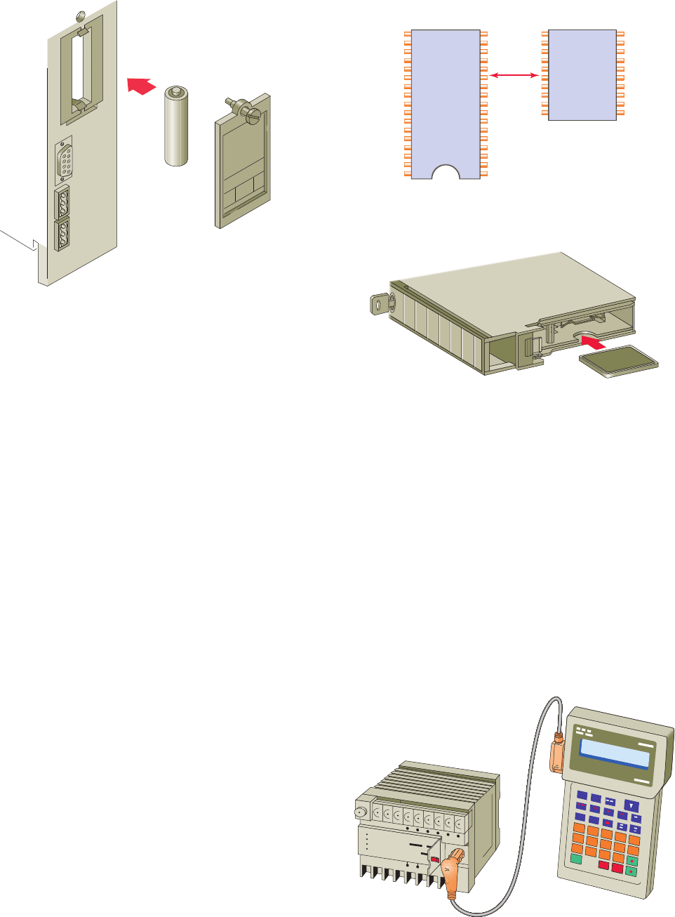
Erasable Programmable Read-Only Memory
(EPROM) provides some level of security against unau-
thorized or unwanted changes in a program. EPROMs are
designed so that data stored in them can be read, but not
easily altered without special equipment. For example,
UV EPROMs (ultraviolet erasable programmable read-
only memory) can only be erased with an ultraviolet light.
EPROM memory is used to back up, store, or transfer
PLC programs.
Electrically erasable programmable read-only mem-
ory (EEPROM) is a nonvolatile memory that offers the
same programming exibility as does RAM. The EEPROM
can be electrically overwritten with new data instead of
being erased with ultraviolet light. Because the EEPROM
is nonvolatile memory, it does not require battery backup.
It provides permanent storage of the program and can be
changed easily using standard programming devices. Typi-
cally, an EEPROM memory module is used to store, back
up, or transfer PLC programs ( Figure2-43 ).
Flash EEPROMs are similar to EEPROMs in that they
can only be used for backup storage. The main difference
comes in the ash memory: they are extremely fast at sav-
ing and retrieving les. In addition, they do not need to
be physically removed from the processor for reprogram-
ming; this can be done using the circuitry within the pro-
cessor module in which they reside. Flash memory is also
sometimes built into the processor module ( Figure2-44 ),
where it automatically backs up parts of RAM. If power
fails while a PLC with ash memory is running, the PLC
will resume running without having lost any working data
after power is restored.
2.9 Programming Terminal Devices
A programming terminal device is needed to enter, mod-
ify, and troubleshoot the PLC program. PLC manufac-
turers use various types of programming devices. The
simplest type is the hand-held type programmer shown
in Figure2-45 . This proprietary programming device has
a connecting cable so that it can be plugged into a PLC’s
programming port. Certain controllers use a plug-in panel
rather than a hand-held device.
Figure 2-42 Battery used to back up processor RAM.
⫹
⫺
Figure 2-43 EEPROM memory module is used to store,
back up, or transfer PLC programs.
EEPROM
(nonvolatile)
Program
bac
kup
Parameters
RAM
(volatile)
Executed
program
Current
data
Memory
bits,
timers,
counters
Figure 2-44 Flash memory card installed in a socket on
the processor.
Flash
Card
Processor Module
Figure 2-45 Hand-held programming terminal.
pet10882_ch02_017-042.indd 37pet10882_ch02_017-042.indd 37 7/23/10 9:06 PM7/23/10 9:06 PM
38 Chapter 2 PLC Hardware Components
Hand-held programmers are compact, inexpensive,
and easy to use. These units contain multifunction keys
and a liquid-crystal display (LCD) or light-emitting
diode (LED) window. There are usually keys for instruc-
tion entering and editing, and navigation keys for mov-
ing around the program. Hand-held programmers have
limited display capabilities. Some units will display only
the last instruction that has been programmed, whereas
other units will display from two to four rungs of ladder
logic. So-called intelligent hand-held programmers are
designed to support a certain family of PLCs from a spe-
ci c manufacturer.
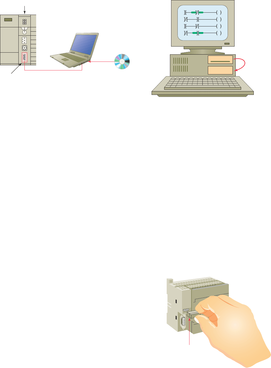
The most popular method of PLC programming is to
use a personal computer (PC) in conjunction with the
manufacturer’s programming software ( Figure 2-46 ).
Typical capabilities of the programming software include
online and of ine program editing, online program moni-
toring, program documentation, diagnosing malfunctions
in the PLC, and troubleshooting the controlled system.
Hard-copy reports generated in the software can be
printed on the computer’s printer. Most software pack-
ages will not allow you to develop programs on another
manufacturer’s PLC. In some cases, a single manufac-
turer will have multiple PLC families, each requiring its
own software to program.
2.10 Recording and Retrieving Data
Printers are used to provide hard-copy printouts of the
processor’s memory in ladder program format. Lengthy
ladder programs cannot be shown completely on a screen.
Typically, a screen shows a maximum of ve rungs at a
time. A printout can show programs of any length and
analyze the complete program.
The PLC can have only one program in memory at
a time. To change the program in the PLC, it is neces-
sary either to enter a new program directly from the
keyboard or to download one from the computer hard
drive ( Figure 2-47 ). Some CPUs support the use of a
memory cartridge that provides portable EEPROM stor-
age for the user program ( Figure2-48 ). The cartridge
can be used to copy a program from one PLC to another
similar type PLC.
2.11 Human Machine Interfaces
(HMIs)
A human machine interface (HMI) can be connected to
communicate with a PLC and to replace pushbuttons, se-
lector switches, pilot lights, thumbwheels, and other op-
erator control panel devices ( Figure2-49 ). Luminescent
touch-screen keypads provide an operator interface that
operates like traditional hardwired control panels.
Human machine interfaces give the ability to the op-
erator and to management to view the operation in real
Figure 2-46 Personal computer used as the programming
device.
Serial port
Laptop computer
Processor
Software
Figure 2-47 Copying programs to a computer hard drive.
A
C
Copy
(Disk drive)
(Internal hard drive)
A
C
Figure 2-48 Memory cartridge provides portable storage
for user program.
Memory cartridge
pet10882_ch02_017-042.indd 38pet10882_ch02_017-042.indd 38 7/23/10 9:06 PM7/23/10 9:06 PM
PLC Hardware Components Chapter 2 39
time. Through personal computer–based setup software,
you can con gure display screens to:
• Replace hardwired pushbuttons and pilot lights
with realistic-looking icons. The machine operator
need only touch the display panel to activate the
pushbuttons.
• Show operations in graphic format for easier viewing.
• Allow the operator to change timer and counter pre-
sets by touching the numeric keypad graphic on the
touch screen.
• Show alarms, complete with time of occurrence and
location.
• Display variables as they change over time.
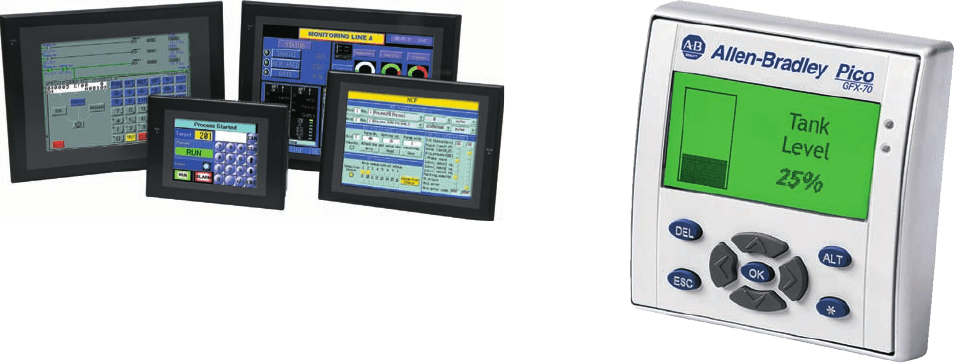
The Allen-Bradley Pico GFX-70 controller, shown in
Figure2-50 , serves as a controller with HMI capabilities.
This device consists of three modular parts: an HMI,
processor/power supply, and I/O modules.
The display/keypad can be used as an operator inter-
face or can be linked to control operations to provide real-
time feedback. It has the ability to show text, date and
time, as well as custom messages and bitmap graphics,
allowing operators to acknowledge fault messages, enter
values, and initiate actions. Users can create both the
control program and HMI functionality using a personal
computer with PicoSoft Pro software installed or the con-
troller’s on-board display buttons.
Figure 2-49 Human Machine Interfaces (HMIs).
Source: Photo courtesy Omron Industrial Automation, www.ia.omron.com.
Figure 2-50 Allen-Bradley Pico GFX-70 controller.
Source: Image Used with Permission of Rockwell Automation, Inc.
pet10882_ch02_017-042.indd 39pet10882_ch02_017-042.indd 39 7/23/10 9:06 PM7/23/10 9:06 PM

40 Chapter 2 PLC Hardware Components
1. What is the function of a PLC input interface
module?
2. What is the function of a PLC output interface
module?
3. D e ne the term logical rack.
4. With reference to a PLC rack:
a. What is a remote rack?
b. Why are remote racks used?
5. How does the processor identify the location of a
speci c input or output device?
6. List the three basic elements of rack/slot-based
addressing.
7. Compare bit level and word level addressing.
8. In what way does tag-based addressing differ from
rack/slot-based addressing?
9. What do PC-based control systems use to interface
with eld devices?
10. What type of I/O modules have both inputs and
outputs connected to them?
11. In addition to eld devices what other connections
are made to a PLC module?
12. Most PLC modules use plug-in wiring terminal
strips. Why?
13. What are the advantage and the disadvantage of
using high-density modules?
14. With reference to PLC discrete input modules:
a. What types of eld input devices are suitable for
use with them?
b. List three examples of discrete input devices.
15. With reference to PLC discrete output modules:
a. What types of eld output devices are suitable
for use with them?
b. List three examples of discrete output devices.
16. Explain the function of the backplane of a PLC
rack.
17. What is the function of the optical isolator circuit
used in discrete I/O module circuits?
18. Name the two distinct sections of an I/O module.
19. List four tasks performed by a discrete input
module.
20. What electronic element can be used as the switch-
ing device for a 120 VAC discrete output interface
module?
21. With reference to discrete output module current
ratings:
a. What is the maximum current rating for a typical
120 VAC output module?
b. Explain one method of handling outputs with
larger current requirements.
22. What electronic element can be used as the switch-
ing device for DC discrete output modules?
23. A discrete relay type output module can be used to
switch either AC or DC load devices. Why?
24.
With reference to sourcing and sinking I/O
modules:
a. What current relationship are the terms sourcing
and sinking used to describe?
b. If an I/O module is speci ed as a current-sinking
type, then which type of eld device (sinking or
sourcing) it is electrically compatible with?
25. Compare discrete and analog I/O modules with
respect to the type of input or output devices with
which they can be used.
26. Explain the function of the analog-to-digital (A/D)
converter circuit used in analog input modules.
27. Explain the function of the digital-to-analog (D/A)
converter circuit used in analog output modules.
28. Name the two general sensing classi cations for
analog input modules.
29. List ve common physical quantities measured by
a PLC analog input module.
30. What type of cable is used when connecting a ther-
mocouple to a voltage sensing analog input mod-
ule? Why?
31. Explain the difference between a unipolar and bi-
polar analog input module.
32. The resolution of an analog input channel is speci-
ed as 0.3 mV. What does this tell you?
33. In what two ways can the loop power for current
sensing input modules be supplied?
34. List three eld devices that are commonly controlled
by a PLC analog output module.
35. State one application for each of the following spe-
cial I/O modules:
a. High-speed counter module
b. Thumbwheel module
c. TTL module
CHAPTER 2 REVIEW QUESTIONS
pet10882_ch02_017-042.indd 40pet10882_ch02_017-042.indd 40 7/23/10 9:06 PM7/23/10 9:06 PM

PLC Hardware Components Chapter 2 41
44. List ve important procedures to follow when han-
dling static-sensitive PLC components.
45. D e ne each of the following terms as they apply to
the memory element of a PLC:
a. writing
b. reading
c. bits
d. location
e. utilization
46. With reference to the I/O image tables:
a. What information is stored in PLC input and
output tables?
b. What is the input status of a closed switch
stored as?
c. What is the input status of an open switch
stored as?
d. What is the status of an output that is ON
stored as?
e. What is the status of an output that is OFF
stored as?
47. Why do PLCs execute memory-checking
routines?
48. Compare the memory storage characteristics of
volatile and nonvolatile memory elements.
49. What information is normally stored in the ROM
memory of a PLC?
50. What information is normally stored in the RAM
memory of a PLC?
51. What information is normally stored in an
EEPROM memory module?
52. What are the advantages of a processor that utilizes
a ash memory card?
53. List three functions of a PLC programming termi-
nal device.
54. Give one advantage and one limitation to the use of
hand-held programming devices.
55. What is required for a personal computer to be used
as a PLC programming terminal?
56. List four important capabilities of PLC program-
ming software.
57. How many programs can a PLC have stored in
memory at any one time?
58. Outline four functions that an HMI interface screen
can be con gured to perform.
d. Encoder-counter module
e. BASIC or ASCII module
f. Stepper-motor module
g. BCD-output module
36. List one application for each of the following intel-
ligent I/O modules:
a. PID module
b. Motion and position control module
c. Communication module
37. Write a short explanation for each of the following
discrete I/O module speci
cations:
a. Nominal
input voltage
b. Input threshold voltages
c. Nominal current per input
d. Ambient temperature rating
e. Input ON/OFF delay
f. Output voltage
g. Output current
h. Inrush current
i. Short circuit protection
j. Leakage current
k. Electrical isolation
l. Points per module
m. Backplane current draw
38. Write a short explanation for each of the following
analog I/O module speci cations:
a. Channels per module
b. Input current/voltage range(s)
c. Output current/voltage range(s)
d. Input protection
e. Resolution
f. Input impedance and capacitance
g. Common-mode rejection
39. Compare the function of the CPU and memory sec-
tions of a PLC processor.
40. With reference to the PLC chassis power supply:
a. What conversion of power takes place within the
power supply circuit?
b. Explain the term hold-up time as it applies to the
power supply.
41. Explain the purpose of a redundant PLC processor.
42. Describe three typical modes of operation that can
be selected by the keyswitch of a processor.
43. State ve other functions, in addition to simple
logic processing, that PLC processors are capable
of performing.
pet10882_ch02_017-042.indd 41pet10882_ch02_017-042.indd 41 7/23/10 9:06 PM7/23/10 9:06 PM

42 Chapter 2 PLC Hardware Components
1. A discrete 120 VAC output module is to be used to
control a 230 VDC solenoid valve. Draw a diagram
showing how this could be accomplished using an
interposing relay.
2. Assume a thermocouple, which supplies the input
to an analog input module, generates a linear volt-
age of from 20 mV to 50 mV when the temperature
changes from 750°F to 1250°F. How much voltage
will be generated when the temperature of the
thermocouple is at 1000°F?
3. With reference to I/O module speci cations:
a. If the ON-delay time of a given discrete input
module is speci ed as 12 milliseconds, how much
is this expressed in seconds?
b. If the output leakage current of a discrete output
module is speci ed as 950 μA, how much is this
expressed in amperes?
CHAPTER 2 PROBLEMS
c. If the ambient temperature rating for an I/O
module is speci ed as 60°C, how much is this
expressed in degrees Fahrenheit?
4. Create a ve-digit code using the SLC 500 rack/
slot-based addressing format for each of the
following:
a. A pushbutton connected to terminal 5 of module
group 2 located on rack 1.
b. A lamp connected to terminal 3 of module
group0 located on rack 2.
5. Assume the triac of an AC discrete output module
fails in the shorted state. How would this affect the
device connected to this output?
6. A personal computer is to be used to program sev-
eral different PLCs from different manufacturers.
What would be required?
pet10882_ch02_017-042.indd 42pet10882_ch02_017-042.indd 42 7/23/10 9:06 PM7/23/10 9:06 PM