Petruzella F.D. Programmable Logic Controllers
Подождите немного. Документ загружается.

Programmable Logic Controllers (PLCs) Chapter 1 3
obsolete except for power applications. Generally,
if an application has more than about a half-dozen
control relays, it will probably be less expensive to
install a PLC.
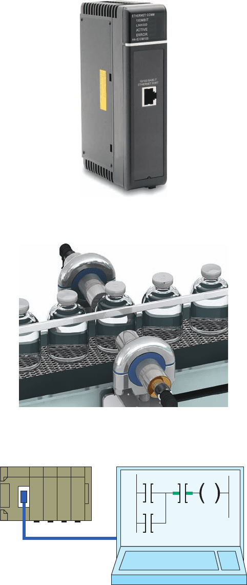
• Communications Capability. A PLC can communi-
cate with other controllers or computer equipment to
perform such functions as supervisory control, data
gathering, monitoring devices and process parameters,
and download and upload of programs ( Figure 1-5 ).
User program
PLC
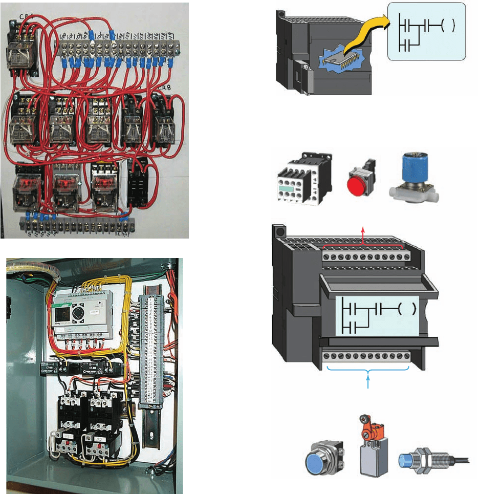
Figure 1-3 All the logic is contained in the PLC’s memory.
Figure 1-4 Relationships between the inputs and outputs
are determined by the user program.
Contactor Light Solenoid
Outputs
Inputs
Pushbutton Limit switch Sensor
• Faster Response Time. PLCs are designed for high-
speed and real-time applications ( Figure 1-6 ). The
programmable controller operates in real time,
which means that an event taking place in the
eld will result in the execution of an operation or
output. Machines that process thousands of items
persecond and objects that spend only a fraction
of a second in front of a sensor require the PLC’s
quick-response capability.
• Easier to Troubleshoot. PLCs have resident diag-
nostics and override functions that allow users to
(a)
(b)
Figure 1-2 Relay- and PLC-based control panels. ( a ) Relay-
based control panel. ( b ) PLC-based control panel.
Source: ( a ) Courtesy Mid-Illini Technical Group, Inc.; ( b ) Photo courtesy Ramco
Electric, Ltd.
pet10882_ch01_001-016.indd 3pet10882_ch01_001-016.indd 3 7/23/10 9:00 PM7/23/10 9:00 PM
4 Chapter 1 Programmable Logic Controllers (PLCs)
easily trace and correct software and hardware prob-
lems. To nd and x problems, users can display the
control program on a monitor and watch it in real
time as it executes ( Figure 1-7 ).
1.2 Parts of a PLC
A typical PLC can be divided into parts, as illustrated in
Figure 1-8 . These are the central processing unit (CPU) ,
the input/output (I/O) section, the power supply, and the
programming device. The term architecture can refer to
PLC hardware, to PLC software, or to a combination of
both. An open architecture design allows the system to be
connected easily to devices and programs made by other
manufacturers. Open architectures use off-the-shelf com-
ponents that conform to approved standards. A system
with a closed architecture is one whose design is propri-
etary, making it more dif cult to connect to other systems.
Most PLC systems are in fact proprietary, so you must be
sure that any generic hardware or software you may use
is compatible with your particular PLC. Also, although
the principal concepts are the same in all methods of pro-
gramming, there might be slight differences in address-
ing, memory allocation, retrieval, and data handling for
different models. Consequently, PLC programs cannot be
interchanged among different PLC manufacturers.
There are two ways in which I/Os (Inputs/Outputs) are
incorporated into the PLC: xed and modular. Fixed I/O
( Figure 1-9 ) is typical of small PLCs that come in one
package with no separate, removable units. The processor
and I/O are packaged together, and the I/O terminals will
have a xed number of connections built in for inputs and
outputs. The main advantage of this type of packaging is
lower cost. The number of available I/O points varies and
usually can be expanded by buying additional units of
xed I/O. One disadvantage of xed I/O is its lack of ex-
ibility; you are limited in what you can get in the quanti-
ties and types dictated by the packaging. Also, for some
models, if any part in the unit fails, the whole unit has to
be replaced.
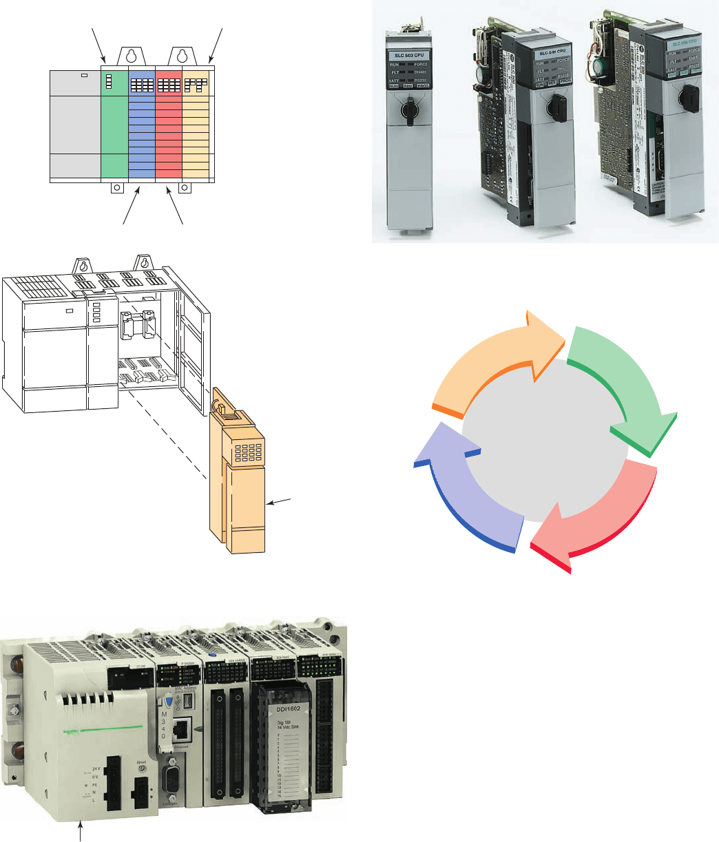
Modular I/O ( Figure 1-10 ) is divided by compartments
into which separate modules can be plugged. This fea-
ture greatly increases your options and the unit’s exibil-
ity. You can choose from the modules available from the
manufacturer and mix them any way you desire. The basic
modular controller consists of a rack, power supply, pro-
cessor module (CPU), input/output (I/O modules), and an
operator interface for programming and monitoring. The
modules plug into a rack. When a module is slid into the
rack, it makes an electrical connection with a series of con-
tacts called the backplane, located at the rear of the rack.
The PLC processor is also connected to the backplane and
can communicate with all the modules in the rack.
The power supply supplies DC power to other modules
that plug into the rack ( Figure 1-11 ). For large PLC systems,
this power supply does not normally supply power to the
eld devices. With larger systems, power to eld devices is
Figure 1-7 Control program can be displayed on a monitor
in real time.
PLC Monitor
Figure 1-5 PLC communication module.
Source: Photo courtesy Automation Direct, www.automationdirect.com.
Figure 1-6 High-speed counting.
Source: Courtesy Banner Engineering Corp.
pet10882_ch01_001-016.indd 4pet10882_ch01_001-016.indd 4 7/27/10 9:58 PM7/27/10 9:58 PM
Programmable Logic Controllers (PLCs) Chapter 1 5
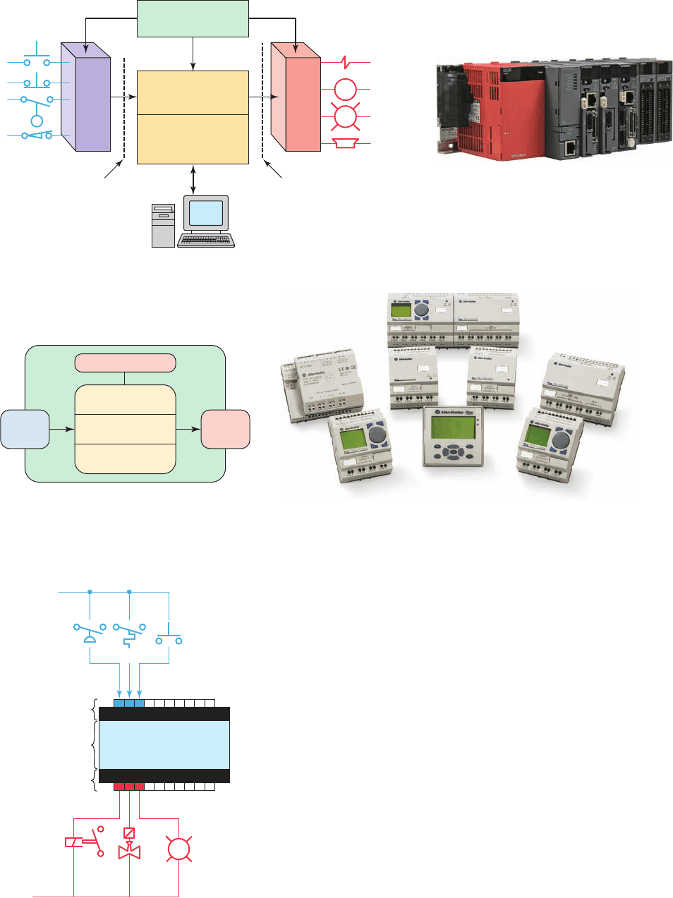
(b) Fixed type
Power supply
Communications
Input
section
Output
section
Memory
CPU
M
(a) Modular type
Central
Processing
Unit (CPU)
Programming device
Memory
Input
sensing
devices
Output
load
devices
Program Data
Optical
isolation
Input
module
Output
module
Processor Module
Optical
isolation
Power supply
module
Figure 1-8 Typical parts of a programmable logic controller.
Source: ( a ) Courtesy Mitsubishi Automation; ( b ) Image Used with Permission of Rockwell Automation, Inc.
Figure 1-9 Fixed I/O confi guration.
PL
Input
connections
Common power bus
Common return bus
Output
connections
Processor
PLC
provided by external alternating current (AC) or direct cur-
rent (DC) supplies. For some small micro PLC systems, the
power supply may be used to power eld devices.
The processor (CPU) is the “brain” of the PLC. A typi-
cal processor ( Figure 1-12 ) usually consists of a micro-
processor for implementing the logic and controlling the
communications among the modules. The processor re-
quires memory for storing the results of the logical op-
erations performed by the microprocessor. Memory is also
required for the program EPROM or EEPROM plus RAM.
The CPU controls all PLC activity and is designed so
that the user can enter the desired program in relay ladder
logic. The PLC program is executed as part of a repeti-
tive process referred to as a scan ( Figure 1-13 ). A typical
PLC scan starts with the CPU reading the status of inputs.
Then, the application program is executed. Once the pro-
gram execution is completed, the CPU performs internal
diagnostic and communication tasks. Next, the status of
all outputs is updated. This process is repeated continu-
ously as long as the PLC is in the run mode.
pet10882_ch01_001-016.indd 5pet10882_ch01_001-016.indd 5 7/27/10 9:58 PM7/27/10 9:58 PM
6 Chapter 1 Programmable Logic Controllers (PLCs)
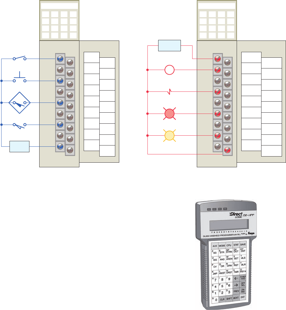
The I/O system forms the interface by which eld de-
vices are connected to the controller ( Figure 1-14 ). The
purpose of this interface is to condition the various sig-
nals received from or sent to external eld devices. Input
devices such as pushbuttons, limit switches, and sensors
are hardwired to the input terminals. Output devices such
as small motors, motor starters, solenoid valves, and in-
dicator lights are hardwired to the output terminals. To
electrically isolate the internal components from the
input and output terminals, PLCs commonly employ an
optical isolator, which uses light to couple the circuits to-
gether. The external devices are also referred to as “ eld”
or “real-world” inputs and outputs. The terms eld or
real world are used to distinguish actual external devices
that exist and must be physically wired from the internal
user program that duplicates the function of relays, tim-
ers, and counters.
Figure 1-11 The power supply supplies DC power to other
modules that plug into the rack.
Source: This material and associated copyrights are proprietary to, and used
with the permission of Schneider Electric.
Power supply
Figure 1-12 Typical PLC processor modules.
Source: Image Used with Permission of Rockwell Automation, Inc.
E
x
e
c
u
t
e
p
r
o
g
r
a
m
D
i
a
g
n
o
s
t
i
c
s
&
c
o
m
m
u
n
i
c
a
t
i
o
n
R
e
a
d
i
n
p
u
t
s
U
p
d
a
t
e
o
u
t
p
u
t
s
Figure 1-13 Typical PLC scan cycle.
Output moduleInput module
Processor
module
Power
supply
Combination
I/O module
Module
slides into
the rack
Figure 1-10 Modular I/O confi guration.
pet10882_ch01_001-016.indd 6pet10882_ch01_001-016.indd 6 7/23/10 9:01 PM7/23/10 9:01 PM
Programmable Logic Controllers (PLCs) Chapter 1 7
A programming device is used to enter the desired pro-
gram into the memory of the processor. The program can
be entered using relay ladder logic, which is one of the
most popular programming languages. Instead of words,
ladder logic programming language uses graphic symbols
that show their intended outcome. A program in ladder
logic is similar to a schematic for a relay control circuit.
It is a special language written to make it easy for peo-
ple familiar with relay logic control to program the PLC.
Hand-held programming devices ( Figure 1-15 ) are some-
times used to program small PLCs because they are inex-
pensive and easy to use. Once plugged into the PLC, they
can be used to enter and monitor programs. Both compact
hand-held units and laptop computers are frequently used
on the factory oor for troubleshooting equipment, modi-
fying programs, and transferring programs to multiple
machines.
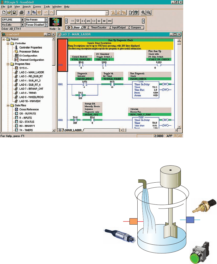
A personal computer (PC) is the most commonly used
programming device. Most brands of PLCs have software
available so that a PC can be used as the programming
device. This software allows users to create, edit, docu-
ment, store, and troubleshoot ladder logic programs ( Fig-
ure 1-16 ). The computer monitor is able to display more
logic on the screen than can hand-held types, thus sim-
plifying the interpretation of the program. The personal
computer communicates with the PLC processor via a se-
rial or parallel data communications link, or Ethernet. If
the programming unit is not in use, it may be unplugged
and removed. Removing the programming unit will not
affect the operation of the user program.
A program is a user-developed series of instructions
that directs the PLC to execute actions. A programming
language provides rules for combining the instructions
so that they produce the desired actions. Relay ladder
logic (RLL) is the standard programming language used
Input module
0
1
2
3
4
5
6
7
8
9
10
11
12
13
14
15
IN 0
IN 2
IN 4
IN 6
IN 8
IN 10
IN 12
IN 14
DC
COM
IN 1
IN 3
IN 5
IN 7
IN 9
IN 11
IN 13
IN 15
DC
COM
Output module
0
1
2
3
4
5
6
7
8
9
10
11
12
13
14
15
VAC
OUT 1
OUT 3
OUT 5
OUT 7
OUT 9
OUT 11
OUT 13
OUT 15
OUT 0
OUT 2
OUT 4
OUT 6
OUT 8
OUT 10
OUT 12
OUT 14
AC
COM
24 VDC
input
module
240 VAC
output
module
24 VDC
Field device
power supply
+–
240 VAC
M
Field device
power supply
L2 L1
R
Y
Figure 1-14 Typical PLC input/output (I/O) system connections.
Figure 1-15 Typical hand-held programming device.
Source: Photo courtesy Automation Direct, www.automationdirect.com.
pet10882_ch01_001-016.indd 7pet10882_ch01_001-016.indd 7 7/23/10 9:01 PM7/23/10 9:01 PM
8 Chapter 1 Programmable Logic Controllers (PLCs)
with PLCs. Its origin is based on electromechanical relay
control. The relay ladder logic program graphically rep-
resents rungs of contacts, coils, and special instruction
blocks. RLL was originally designed for easy use and un-
derstanding for its users and has been modi ed to keep up
with the increasing demands of industry’s control needs.
1.3 Principles of Operation
To get an idea of how a PLC operates, consider the simple
process control problem illustrated in Figure 1-17 . Here a
mixer motor is to be used to automatically stir the liquid
in a vat when the temperature and pressure reach preset
values. In addition, direct manual operation of the motor
is provided by means of a separate pushbutton station.
The process is monitored with temperature and pressure
sensor switches that close their respective contacts when
conditions reach their preset values.
This control problem can be solved using the relay
method for motor control shown in the relay ladder dia-
gram of Figure 1-18 . The motor starter coil (M) is energized
when both the pressure and temperature switches are closed
or when the manual pushbutton is pressed.
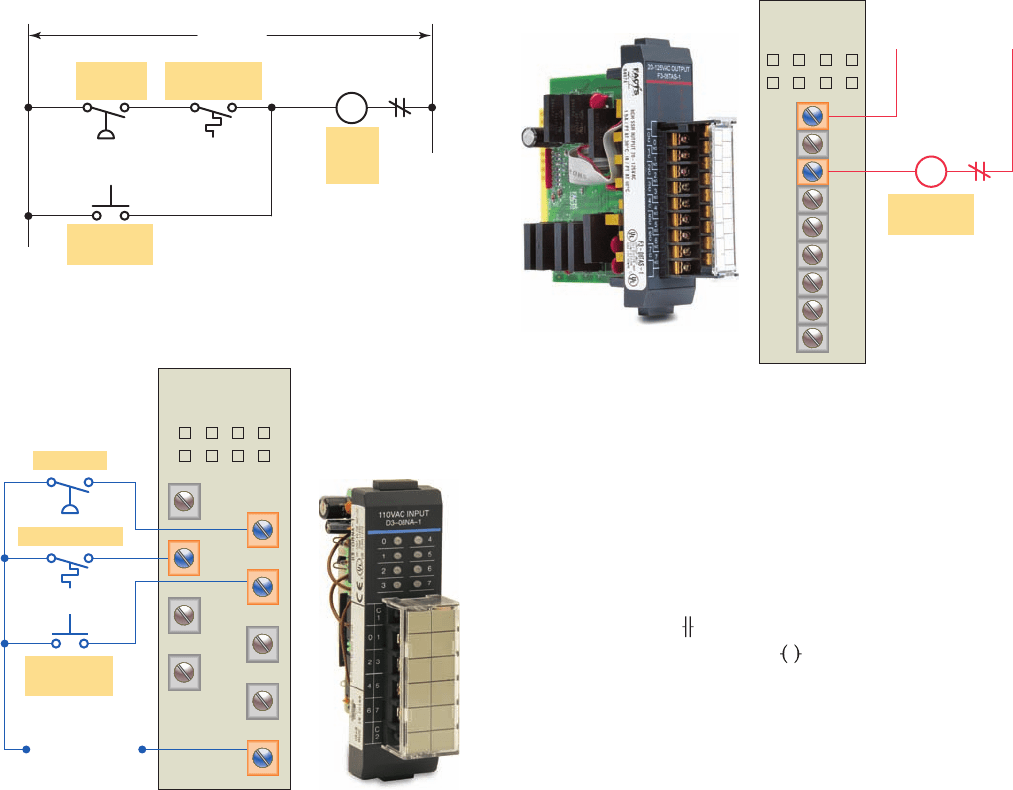
Now let’s look at how a programmable logic controller
might be used for this application. The same input eld
devices (pressure switch, temperature switch, and push-
button) are used. These devices would be hardwired to an
appropriate input module according to the manufacturer’s
addressing location scheme. Typical wiring connections
for a 120 VAC modular con gured input module is shown
in Figure 1-19 .
The same output eld device (motor starter coil) would
also be used. This device would be hardwired to an appropri-
ate output module according to the manufacturer’s addressing
location scheme. Typical wiring connections for a 120 VAC
modular con gured output module is shown in Figure 1-20 .
Figure 1-16 Typical PC software used to create a ladder logic program.
Source: Image Used with Permission of Rockwell Automation, Inc.
Pressure
sensor
switch
Motor
Temperature
sensor switch
Manual pushbutton station
Figure 1-17 Mixer process control problem.
pet10882_ch01_001-016.indd 8pet10882_ch01_001-016.indd 8 7/23/10 9:01 PM7/23/10 9:01 PM
Programmable Logic Controllers (PLCs) Chapter 1 9
L1 L2
M
OL
Manual
pushbutton
120 VAC
Motor
starter
coil
Temperature
switch
Pressure
switch
Figure 1-18 Process control relay ladder diagram.
Common
0
1
2
3
4
5
6
7
Input
module
L1 N
120 VAC
Manual
pushbutton
Temperature
Pressure
Figure 1-19 Typical wiring connections for a 120 VAC
modular confi gured input module.
Source: Photo courtesy Automation Direct, www.automationdirect.com.
Output
module
120 VAC
NL1
L1
0
1
2
3
4
5
6
7
Motor
starter coil
M
OL
Figure 1-20 Typical wiring connections for a 120 VAC
modular confi gured output module.
Source: Photo courtesy Automation Direct, www.automationdirect.com.
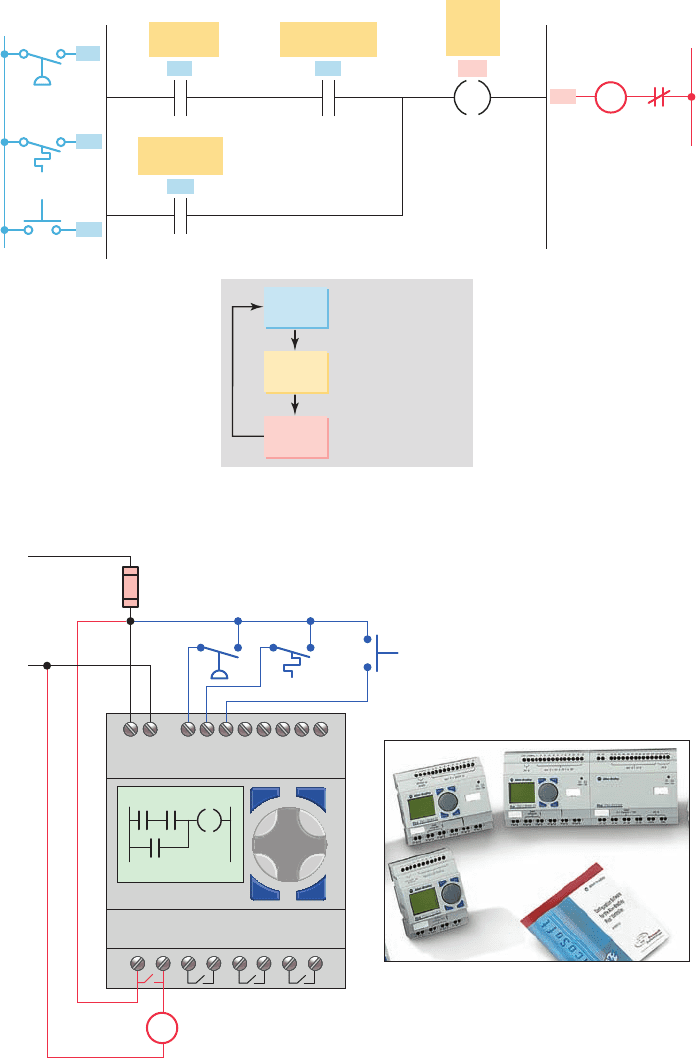
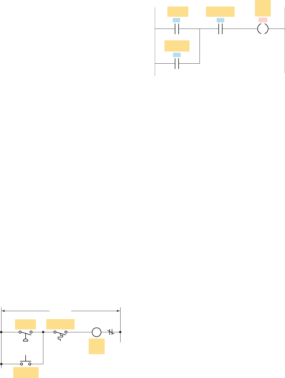
Next, the PLC ladder logic program would be con-
structed and entered into the memory of the CPU. A
typical ladder logic program for this process is shown in
Figure 1-21 . The format used is similar to the layout of
the hardwired relay ladder circuit. The individual symbols
represent instructions, whereas the numbers represent the
instruction location addresses. To program the controller,
you enter these instructions one by one into the proces-
sor memory from the programming device. Each input
and output device is given an address, which lets the PLC
know where it is physically connected. Note that the I/O
address format will differ, depending on the PLC model
and manufacturer. Instructions are stored in the user pro-
gram portion of the processor memory. During the pro-
gram scan the controller monitors the inputs, executes the
control program, and changes the output accordingly.
For the program to operate, the controller is placed
in the RUN mode, or operating cycle. During each op-
erating cycle, the controller examines the status of input
devices, executes the user program, and changes outputs
accordingly. Each
symbol can be thought of as a set of
normally open contacts. The
symbol is considered to
represent a coil that, when energized, will close a set of
contacts. In the ladder logic program of Figure 1-21 , the
coil O/1 is energized when contacts I/1 and I/2 are closed
or when contact I/3 is closed. Either of these conditions
provides a continuous logic path from left to right across
the rung that includes the coil.
A programmable logic controller operates in real time
in that an event taking place in the eld will result in an
operation or output taking place. The RUN operation for
the process control scheme can be described by the fol-
lowing sequence of events:
• First, the pressure switch, temperature switch, and
pushbutton inputs are examined and their status is
recorded in the controller’s memory.
• A closed contact is recorded in memory as logic 1
and an open contact as logic 0.
• Next the ladder diagram is evaluated, with each
internal contact given an OPEN or CLOSED status
according to its recorded 1 or 0 state.
• When the states of the input contacts provide logic
continuity from left to right across the rung, the
output coil memory location is given a logic 1 value
and the output module interface contacts will close.
• When there is no logic continuity of the program
rung, the output coil memory location is set to logic0
pet10882_ch01_001-016.indd 9pet10882_ch01_001-016.indd 9 7/23/10 9:01 PM7/23/10 9:01 PM
10 Chapter 1 Programmable Logic Controllers (PLCs)
and the output module interface contacts will be
open.
• The completion of one cycle of this sequence by the
controller is called a scan. The scan time, the time
required for one full cycle, provides a measure of
the speed of response of the PLC.
• Generally, the output memory location is updated
during the scan but the actual output is not
updateduntil the end of the program scan during
theI/O scan.
Figure 1-22 shows the typical wiring required to im-
plement the process control scheme using a xed PLC
O/1
Motor
starter
coil
I/1
I/1
Pressure
switch
I/2
I/2
O/1
Temperature
switch
I/3
I/3
Manual
pushbutton
L2
L1
Inputs OutputProgram
Monitor
inputs
Checks the
inputs
Execute
program
Change
outputs
...
Executes control
program
...
And updates the
outputs
...
M
OL
Figure 1-21 Process control PLC ladder logic program with typical addressing scheme.
I1
I1 I2 I3L1 L2
I2Q1
I3
L1
L2
M Starter
Inputs
Pressure
Temp
PB
Outputs
Program
Q1 Q2 Q3 Q4
Figure 1-22 Typical wiring required to implement the process control scheme
using a fi xed PLC controller.
Source: Image Used with Permission of Rockwell Automation, Inc.
pet10882_ch01_001-016.indd 10pet10882_ch01_001-016.indd 10 7/23/10 9:01 PM7/23/10 9:01 PM
Programmable Logic Controllers (PLCs) Chapter 1 11
controller. In this example the Allen-Bradley Pico con-
troller equipped with 8 inputs and 4 outputs is used to
control and monitor the process. Installation can be sum-
marized as follows:
• Fused power lines, of the speci ed voltage type and
level, are connected to the controller’s L1 and L2
terminals.
• The pressure switch, temperature switch, and push-
button eld input devices are hardwired between
L1 and controller input terminals I1, I2, and I3,
respectively.
• The motor starter coil connects directly to L2 and in
series with Q1 relay output contacts to L1.
• The ladder logic program is entered using the front
keypad and LCD display.
• Pico programming software is also available that
allows you to create as well as test your program
using a personal computer.
1.4 Modifying the Operation
One of the important features of a PLC is the ease with
which the program can be changed. For example, assume
that the original process control circuit for the mixing op-
eration must be modi ed as shown in the relay ladder dia-
gram of Figure 1-23 . The change requires that the manual
pushbutton control be permitted to operate at any pres-
sure, but not unless the speci ed temperature setting has
been reached.
If a relay system were used, it would require some re-
wiring of the circuit shown in Figure 1-23 to achieve the
desired change. However, if a PLC system were used, no
rewiring would be necessary. The inputs and outputs are
still the same. All that is required is to change the PLC
ladder logic program as shown in Figure 1-24 .
1.5 PLCs versus Computers
The architecture of a PLC is basically the same as that
of a personal computer. A personal computer (PC) can
be made to operate as a programmable logic control-
ler if you provide some way for the computer to re-
ceive information from devices such as pushbuttons
or switches. You also need a program to process the
inputs and decide the means of turning load devices
off and on.
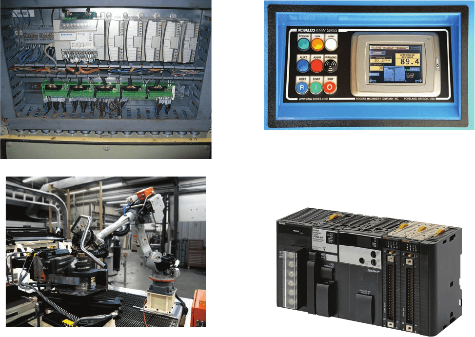
However, some important characteristics distinguish
PLCs from personal computers. First, unlike PCs, the
PLC is designed to operate in the industrial environ-
ment with wide ranges of ambient temperature and
humidity. A well-designed industrial PLC installation,
such as that shown in Figure 1-25 , is not usually af-
fected by the electrical noise inherent in most industrial
locations.
Unlike the personal computer, the PLC is programmed
in relay ladder logic or other easily learned languages.
The PLC comes with its program language built into its
memory and has no permanently attached keyboard, CD
drive, or monitor. Instead, PLCs come equipped with ter-
minals for input and output eld devices as well as com-
munication ports.
Computers are complex computing machines capable
of executing several programs or tasks simultaneously
and in any order. Most PLCs, on the other hand, execute a
single program in an orderly and sequential fashion from
rst to last instruction.
PLC control systems have been designed to be easily
installed and maintained. Troubleshooting is simpli ed
by the use of fault indicators and messaging displayed
on the programmer screen. Input/output modules for
connecting the eld devices are easily connected and
replaced.
L1 L2
Manual
pushbutton
120 VAC
Motor
starter
coil
Temperature
switch
Pressure
switch
M
OL
Figure 1-23 Relay ladder diagram for the modifi ed
process.
O/1
Motor
starter
coil
I/1
Pressure
switch
I/2
Temperature
switch
I/3
Manual
pushbutton
Figure 1-24 PLC ladder logic program for the modifi ed
process.
pet10882_ch01_001-016.indd 11pet10882_ch01_001-016.indd 11 7/23/10 9:01 PM7/23/10 9:01 PM
12 Chapter 1 Programmable Logic Controllers (PLCs)
Software associated with a PLC but written and run on
a personal computer falls into the following two broad
categories:
• PLC software that allows the user to program and
document gives the user the tools to write a PLC
program—using ladder logic or another program-
ming language—and document or explain the
program in as much detail as is necessary.
• PLC software that allows the user to monitor
and control the process is also called a human
machine interface (HMI). It enables the user to
view a process—or a graphical representation of a
process—on a monitor, determine how the system
is running, trend values, and receive alarm condi-
tions ( Figure1-26 ). Many operator interfaces do
not use PLC software. PLCs can be integrated with
HMIs but the same software does not program both
devices.
Most recently automation manufacturers have responded
to the increased requirements of industrial control systems
by blending the advantages of PLC-style control with
that of PC-based systems. Such a device has been termed
a programmable automation controller, or PAC ( Fig-
ure1-27 ). Programmable automation controllers combine
PLC ruggedness with PC functionality. Using PACs, you
can build advanced systems incorporating software capa-
bilities such as advanced control, communication, data
logging, and signal processing with rugged hardware per-
forming logic, motion, process control, and vision.
1.6 PLC Size and Application
The criteria used in categorizing PLCs include functional-
ity, number of inputs and outputs, cost, and physical size
( Figure 1-28 ). Of these, the I/O count is the most impor-
tant factor. In general, the nano is the smallest size with
less than 15 I/O points. This is followed by micro types
(15 to 128 I/O points), medium types (128 to 512 I/O
points), and large types (over 512 I/O points).
Matching the PLC with the application is a key factor
in the selection process. In general it is not advisable to
Figure 1-26 PLC operator interface and monitor.
Source: Courtesy Rogers Machinery Company, Inc.
Figure 1-27 Programmable automation controller (PAC).
Source: Photo courtesy Omron Industrial Automation, www.ia.omron.com.
(a)
(b)
Figure 1-25 PLC installed in an industrial environment.
Source: (a–b) Courtesy Automation IG.
pet10882_ch01_001-016.indd 12pet10882_ch01_001-016.indd 12 7/23/10 9:01 PM7/23/10 9:01 PM