Petruzella F.D. Programmable Logic Controllers
Подождите немного. Документ загружается.

Programmable Logic Controllers (PLCs) Chapter 1 13
buy a PLC system that is larger than current needs dic-
tate. However, future conditions should be anticipated to
ensure that the system is the proper size to ll the current
and possibly future requirements of an application.
There are three major types of PLC application: single-
ended, multitask, and control management. A single-
ended or stand-alone PLC application involves one PLC
controlling one process ( Figure 1-29 ). This would be a
stand-alone unit and would not be used for communicat-
ing with other computers or PLCs. The size and sophisti-
cation of the process being controlled are obvious factors
in determining which PLC to select. The applications
could dictate a large processor, but usually this category
requires a small PLC.
A multitask PLC application involves one PLC control-
ling several processes. Adequate I/O capacity is a signi -
cant factor in this type of installation. In addition, if the PLC
would be a subsystem of a larger process and would have to
communicate with a central PLC or computer, provisions
for a data communications network are also required.
A control management PLC application involves one
PLC controlling several others ( Figure 1-30 ). This kind
of application requires a large PLC processor designed to
communicate with other PLCs and possibly with a com-
puter. The control management PLC supervises several
PLCs by downloading programs that tell the other PLCs
what has to be done. It must be capable of connection to
all the PLCs so that by proper addressing it can communi-
cate with any one it wishes to.
Memory is the part of a PLC that stores data, instruc-
tions, and the control program. Memory size is usually
expressed in K values: 1 K, 6 K, 12 K, and so on. The
measurement kilo, abbreviated K, normally refers to
1000units. When dealing with computer or PLC memory,
however, 1 K means 1024, because this measurement is
based on the binary number system (210 = 1024). Depend-
ing on memory type, 1 K can mean 1024 bits, 1024 bytes,
or 1024words.
Although it is common for us to measure the memory
capacity of PLCs in words, we need to know the num-
ber of bits in each word before memory size can be accu-
rately compared. Modern computers usually have a word
size of 16, 32, or 64 bits. For example, a PLC that uses
8-bit words has 49,152 bits of storage with a 6 K word
capacity (8 3 6 3 1024 5 49,152), whereas a PLC using
32-bit words has 196,608 bits of storage with the same
6 K memory (32 3 6 3 1024 5 196,608). The amount
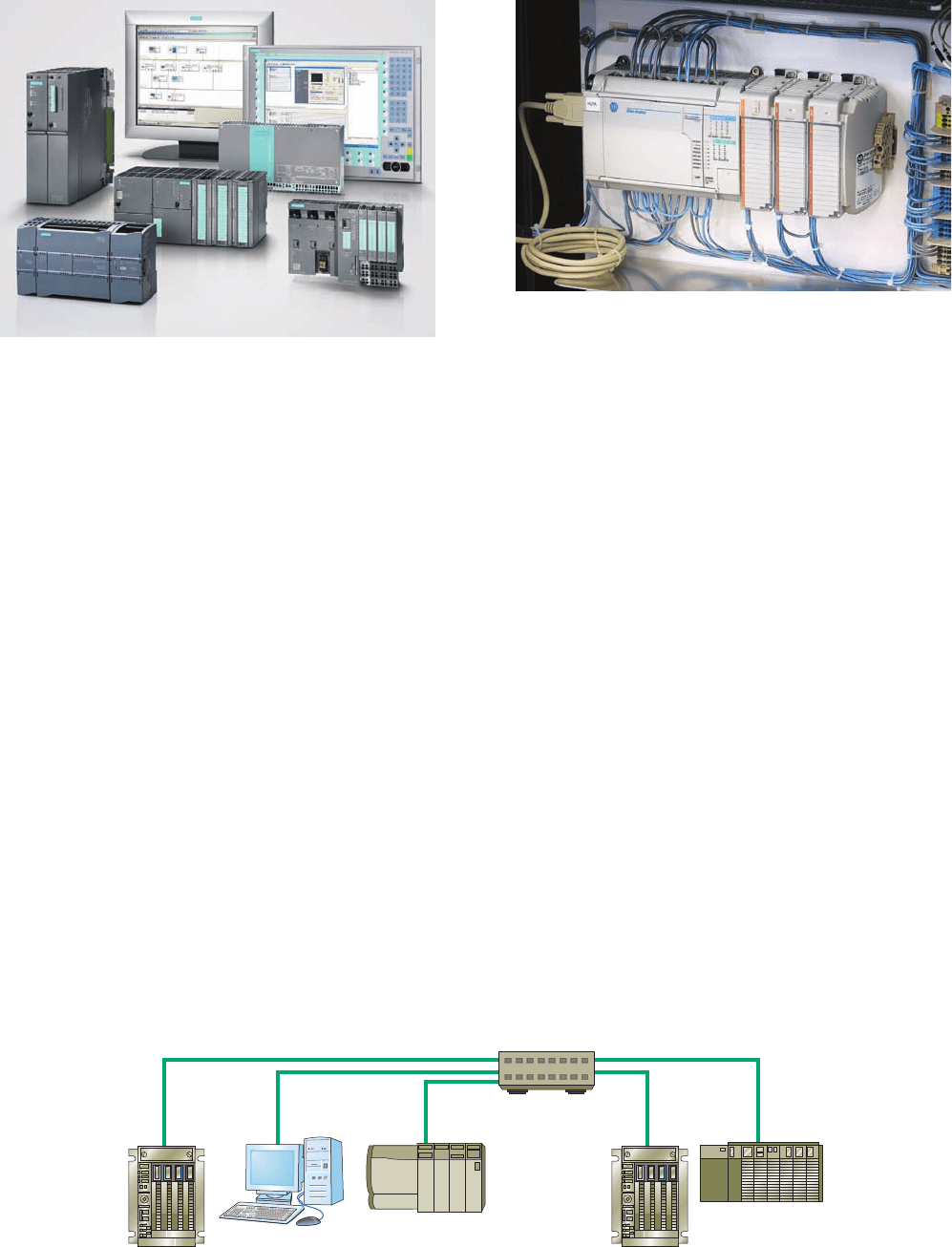
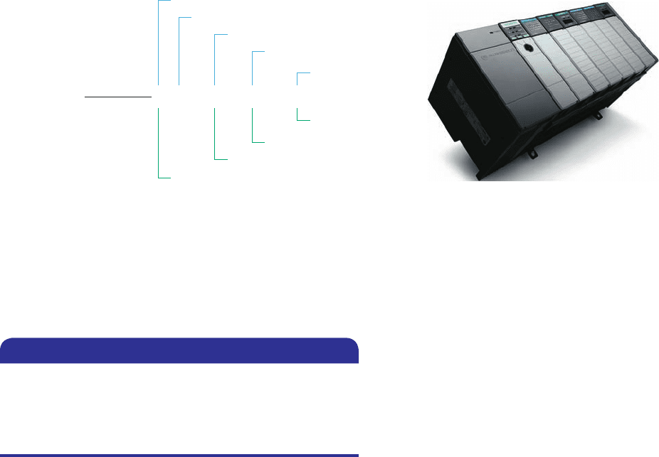
Figure 1-28 Typical range of sizes of programmable
controllers.
Source: Courtesy Siemens.
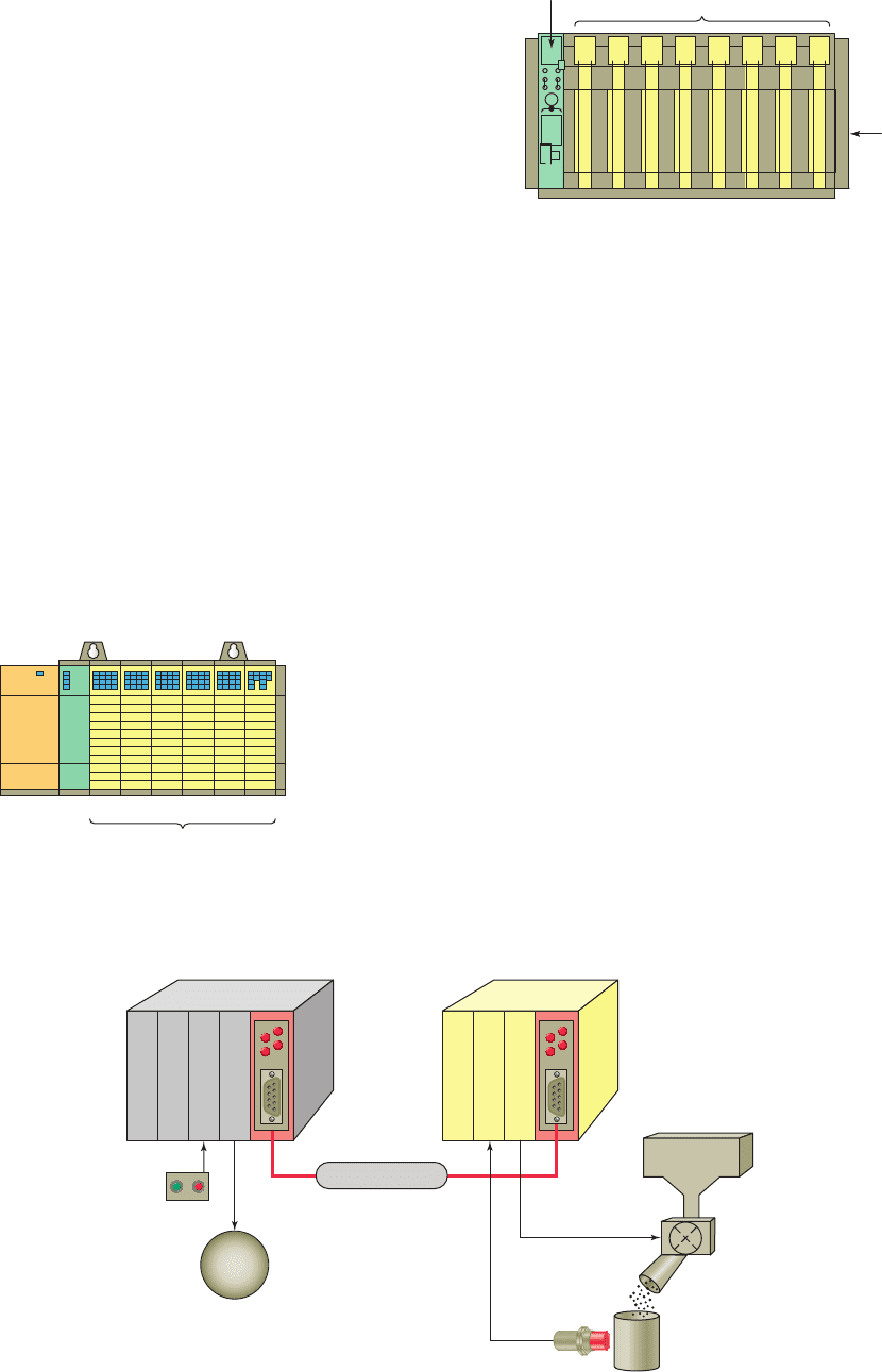
Figure 1-29 Single-ended PLC application.
Source: Courtesy Rogers Machinery Company, Inc.
Figure 1-30 Control management PLC application.
pet10882_ch01_001-016.indd 13pet10882_ch01_001-016.indd 13 7/23/10 9:02 PM7/23/10 9:02 PM

14 Chapter 1 Programmable LogicControllers (PLCs)
Table 1-1 Typical PLC Instructions
Instruction
Operation
XIC (Examine ON) . . . . . . . . . . . . Examine a bit for an ON condition
XIO (Examine OFF) . . . . . . . . . . . Examine a bit for an OFF condition
OTE (Output Energize) . . . . . . . . . Turn ON a bit (nonretentive)
OTL (Output Latch) . . . . . . . . . . . Latch a bit (retentive)
OTU (Output Unlatch) . . . . . . . . . Unlatch a bit (retentive)
TOF (Timer Off-Delay) . . . . . . . . . Turn an output ON or OFF after its rung has been OFF for a preset time interval
TON (Timer On-Delay) . . . . . . . . . Turn an output ON or OFF after its rung has been ON for a preset time interval
CTD (Count Down) . . . . . . . . . . . Use a software counter to count down from a specied value
CTU (Count Up) . . . . . . . . . . . . . . Use a software counter to count up to a specied value
of memory required depends on the application. Factors
affecting the memory size needed for a particular PLC
installation include:
• Number of I/O points used
• Size of control program
• Data-collecting requirements
• Supervisory functions required
• Future expansion
The instruction set for a particular PLC lists the differ-
ent types of instructions supported. Typically, this ranges
from 15 instructions on smaller units up to 100 instruc-
tions on larger, more powerful units (see Table 1-1).
pet10882_ch01_001-016.indd 14pet10882_ch01_001-016.indd 14 7/23/10 9:02 PM7/23/10 9:02 PM

Programmable LogicControllers (PLCs) Chapter 1 15
1. What is a programmable logic controller (PLC)?
2. Identify four tasks in addition to relay switching
operations that PLCs are capable of performing.
3. List six distinct advantages that PLCs offer over
conventional relay-based control systems.
4. Explain the differences between open and propri-
etary PLC architecture.
5. State two ways in which I/O is incorporated into
the PLC.
6. Describe how the I/O modules connect to the pro-
cessor in a modular-type PLC con guration.
7. Explain the main function of each of the following
major components of a PLC:
a. Processor module (CPU)
b. I/O modules
c. Programming device
d. Power supply module
8. What are the two most common types of PLC pro-
gramming devices?
9. Explain the terms program and programming lan-
guage as they apply to a PLC.
10. What is the standard programming language used
with PLCs?
11. Answer the following with reference to the process
control relay ladder diagram of Figure 1-18 of this
chapter:
a. When do the pressure switch contacts close?
b. When do the temperature switch contacts close?
c. How are the pressure and temperature switches
connected with respect to each other?
d. Describe the two conditions under which the
motor starter coil will become energized.
e. What is the approximate value of the voltage
drop across each of the following when their
contacts are open?
(1) Pressure switch
(2) Temperature switch
(3) Manual pushbutton
12. The programmable controller operates in real time.
What does this mean?
13. Answer the following with reference to the process
control PLC ladder logic diagram of Figure 1-21 of
this chapter:
a. What do the individual symbols represent?
b. What do the numbers represent?
c. What eld device is the number I/2 identi ed
with?
d. What eld device is the number O/1 identi ed
with?
e. What two conditions will provide a continuous
path from left to right across the rung?
f. Describe the sequence of operation of the
controller for one scan of the program.
14. Compare the method by which the process control
operation is changed in a relay-based system to the
method used for a PLC-based system.
15. Compare the PLC and PC with regard to:
a. Physical hardware differences
b. Operating
environment
c. Method of programming
d. Execution of program
16. What two categories of software written and run on
PCs are used in conjunction with PLCs?
17. What is a programmable automation controller
(PAC)?
18. List four criteria by which PLCs are categorized.
19. Compare the single-ended, multitask, and control
management types of PLC applications.
20. What is the memory capacity, expressed in bits, for
a PLC that uses 16-bit words and has an 8 K word
capacity?
21. List ve factors affecting the memory size needed
for a particular PLC installation.
22. What does the instruction set for a particular PLC
refer to?
CHAPTER 1 REVIEW QUESTIONS
1. Given two single-pole switches, write a program
that will turn on an output when both switch A and
switch B are closed.
CHAPTER 1 PROBLEMS
2. Given two single-pole switches, write a program that
will turn on an output when either switch A or switch
B is closed.
pet10882_ch01_001-016.indd 15pet10882_ch01_001-016.indd 15 7/23/10 9:02 PM7/23/10 9:02 PM

16 Chapter 1 Programmable LogicControllers (PLCs)
5. Write a program for the relay ladder diagram shown
in Figure 1-32 .
3. Given four NO (Normally Open) pushbuttons (A-
B-C-D), write a program that will turn a lamp on if
pushbuttons A and B or C and D are closed.
4. Write a program for the relay ladder diagram shown
in Figure 1-31 .
120 VAC
S3
TS1
PB1
S2
S1
PS1
L1
Figure 1-32 Circuit for Problem 5.
LS2
120 VAC
S1
LS1
L1
Figure 1-31 Circuit for Problem 4.
pet10882_ch01_001-016.indd 16pet10882_ch01_001-016.indd 16 7/23/10 9:02 PM7/23/10 9:02 PM
17
This chapter exposes you to the details of PLC
hardware and modules that make up a PLC con-
trol system. The chapter’s illustrations show the
various subparts of a PLC as well as general
connection paths. In this chapter we discuss
the CPU and memory hardware components,
including the various types of memory that are
available, and we describe the hardware of the
input/output section, including the difference be-
tween the discrete and analog types of modules.
Chapter Objectives
After completing this chapter, you will be able to:
2.1 List and describe the function of the hardware
components used in PLC systems
2.2 Describe the basic circuitry and applications for
discrete and analog I/O modules, and interpret typical
I/O and CPU speci cations
2.3 Explain I/O addressing
2.4 Describe the general classes and types of PLC
memory devices
2.5 List and describe the different types of PLC
peripheral support devices available
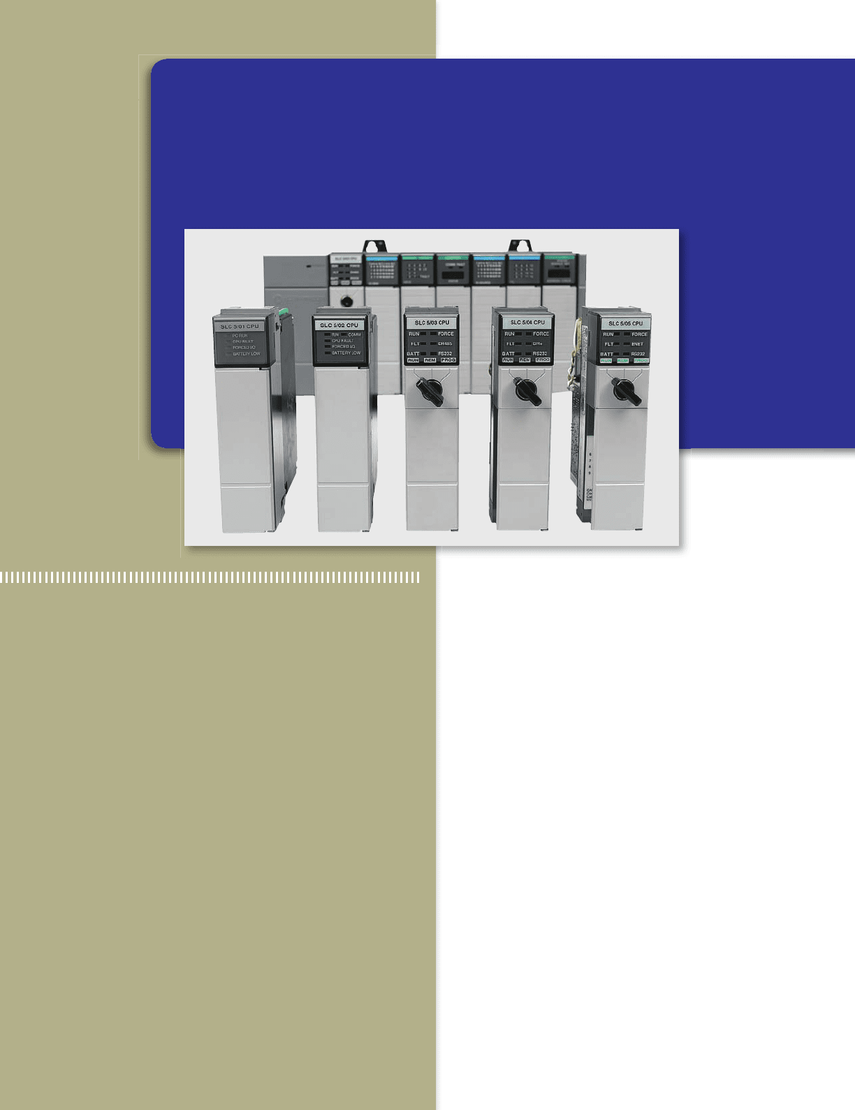
2
PLC Hardware Components
Image Used with Permission of Rockwell Automation, Inc.
pet10882_ch02_017-042.indd 17pet10882_ch02_017-042.indd 17 7/23/10 9:03 PM7/23/10 9:03 PM
18 Chapter 2 PLC Hardware Components
communicate operating signals through the output inter-
face to the process devices under its control.
Allen-Bradley controllers make a distinction between
a PLC chassis and rack as illustrated in Figure2-2 . The
hardware assembly that houses I/O modules, processor
modules, and power supplies is referred to as the chassis.
Chassis come in different sizes according to the number
of slots they contain. In general, they can have 4, 8, 12,
or 16 slots.
A logical rack is an addressable unit consisting of 128
input points and 128 output points. A rack uses 8 words in
the input image table le and 8 words in the output image
table le. A word in the output image table le and its cor-
responding word in the input image table le are called an
I/O group. A rack can contain a maximum of 8 I/O groups
(numbered from 0 through 7) for up to 128 discrete I/O.
There can be more than one rack in a chassis and more
than one chassis in a rack.
One bene t of a PLC system is the ability to locate
the I/O modules near the eld devices, as illustrated in
Figure 2-3 , in order to minimize the amount of wiring
2.1 The I/O Section
The input/output (I/O) section of a PLC is the section to
which all eld devices are connected and provides the in-
terface between them and the CPU. Input/output arrange-
ments are built into a xed PLC while modular types use
external I/O modules that plug into the PLC.
Figure2-1 illustrates a rack-based I/O section made
up of individual I/O modules. Input interface modules
accept signals from the machine or process devices and
convert them into signals that can be used by the con-
troller. Output interface modules convert controller sig-
nals into external signals used to control the machine
or process. A typical PLC has room for several I/O
modules, allowing it to be customized for a particular
application by selecting the appropriate modules. Each
slot in the rack is capable of accommodating any type
of I/O module.
The I/O system provides an interface between the hard-
wired components in the eld and the CPU. The input
interface allows status information regarding processes to
be communicated to the CPU, and thus allows the CPU to
Figure 2-3 Remote I/O rack.
Power
Processor
Input
Output
Local I/O
Stop/Start
Hopper
Motor
Power
Input
Output
Remote I/O
Communication
Sensor
On/Off
control
Figure 2-1 Rack-based I/O section.
Power
supply
0 1 2 3 4 5 6 Slot
I/O modules
Processor
module
Figure 2-2 Allen-Bradley PLC chassis and rack.
01234567
8-slot
chassi
s
Processor
128 I/O rack
pet10882_ch02_017-042.indd 18pet10882_ch02_017-042.indd 18 7/23/10 9:03 PM7/23/10 9:03 PM
PLC Hardware Components Chapter 2 19
Slot— The slot number is the physical location of the
I/O module. This may be a combination of the rack
number and the slot number when using expansion
racks.
Word and Bit— The word and bit are used to identify
the actual terminal connection in a particular I/O mod-
ule. A discrete module usually uses only one word,
and each connection corresponds to a different bit that
makes up the word.
With a rack/slot address system the location of a mod-
ule within a rack and the terminal number of a module
to which an input or output device is connected will
determine the device’s address. Figure 2-4 illustrates
the Allen-Bradley PLC-5 controller addressing format.
The following are typical examples of input and output
addresses:
required. The processor receives signals from the remote
input modules and sends signals back to their output mod-
ules via the communication module.
A rack is referred to as a remote rack when it is lo-
cated away from the processor module. To communi-
cate with the processor, the remote rack uses a special
communications network. Each remote rack requires a
unique station number to distinguish one from another.
The remote racks are linked to the local rack through a
communications module. Cables connect the modules
with each other. If ber optic cable is used between the
CPU and I/O rack, it is possible to operate I/O points
from distances greater than 20 miles with no voltage
drop. Coaxial cable will allow remote I/O to be in-
stalled at distances greater than two miles. Fiber optic
cable will not pick up noise caused by adjacent high
power lines or equipment normally found in an indus-
trial environment. Coaxial cable is more susceptible to
this type of noise.
The PLC’s memory system stores information about
the status of all the inputs and outputs. To keep track of
all this information, it uses a system called addressing. An
address is a label or number that indicates where a certain
piece of information is located in a PLC’s memory. Just
as your home address tells where you live in your city, a
device’s or a piece of data’s address tells where informa-
tion about it resides in the PLC’s memory. That way, if a
PLC wants to nd out information about a eld device, it
knows to look in its corresponding address location. Ex-
amples of addressing schemes include rack/slot-based,
versions of which are used in Allen-Bradley PLC-5 and
SLC 500 controllers, tag-based used in Allen-Bradley
ControlLogix controllers, and PC-based control used in
soft PLCs.
In general, rack/slot-based addressing elements include:
Type— The type determines if an input or output is
being addressed.
I1:27/17 Input, fi le 1, rack 2, group 7, bit 17
O0:34/07 Output, fi le 0, rack 3, group 4, bit 7
I1:0/0 Input, fi le 1, rack 0, group 0, bit 0 (Short
form blank 5 0)
O0:1/1 Output, fi le 0, rack 0, group 1, bit 1 (Short
form blank 5 0)
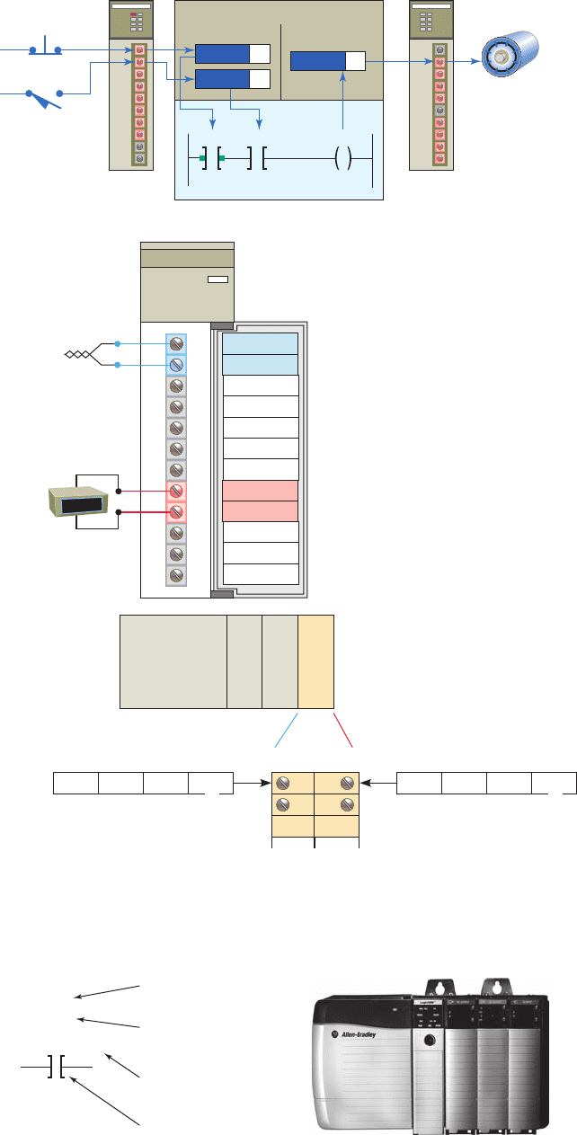
Figure 2-4 Allen-Bradley PLC-5 rack/slot-based addressing format.
Source: Image Used with Permission of Rockwell Automation, Inc.
O 0 : 0 1 / 00
Terminal number (bit address)
Bit delimiter
Group (0–7); 8 groups in a rack
Rack no.
File delimiter
File no.
File type (O—output; Ι—input)
Figure2-5 illustrates the Allen-Bradley SLC 500 con-
troller addressing format. The address is used by the pro-
cessor to identify where the device is located to monitor or
control it. In addition, there is some means of connecting
eld wiring on the I/O module housing. Connecting the
eld wiring to the I/O housing allows easier disconnec-
tion and reconnection of the wiring to change modules.
Lights are also added to each module to indicate the ON
or OFF status of each I/O circuit. Most output modules
also have blown fuse indicators. The following are typical
pet10882_ch02_017-042.indd 19pet10882_ch02_017-042.indd 19 7/27/10 10:41 PM7/27/10 10:41 PM
20 Chapter 2 PLC Hardware Components
in Figure2-9 . A module is made up of a printed circuit
board and a terminal assembly. The printed circuit board
contains the electronic circuitry used to interface the
circuit of the processor with that of the input or output
device. Modules are designed to plug into a slot or con-
nector in the I/O rack or directly into the processor. The
terminal assembly, which is attached to the front edge of
the printed circuit board, is used for making eld-wiring
connections. Modules contain terminals for each input
and output connection, status lights for each of the inputs
and outputs, and connections to the power supply used to
power the inputs and outputs. Terminal and status light
arrangements vary with different manufacturers.
Most PLC modules have plug-in wiring terminal strips.
The terminal block is plugged into the actual module as il-
lustrated in Figure2-10 . If there is a problem with a mod-
ule, the entire strip is removed, a new module is inserted,
and the terminal strip is plugged into the new module.
Unless otherwise speci ed, never install or remove I/O
modules or terminal blocks while the PLC is powered.
A module inserted into the wrong slot could be dam-
aged by improper voltages connected through the wiring
arm. Most faceplates and I/O modules are keyed to pre-
vent putting the wrong faceplate on the wrong module.
In other words, an output module cannot be placed in the
slot where an input module was originally located.
Input and output modules can be placed anywhere in a
rack, but they are normally grouped together for ease of
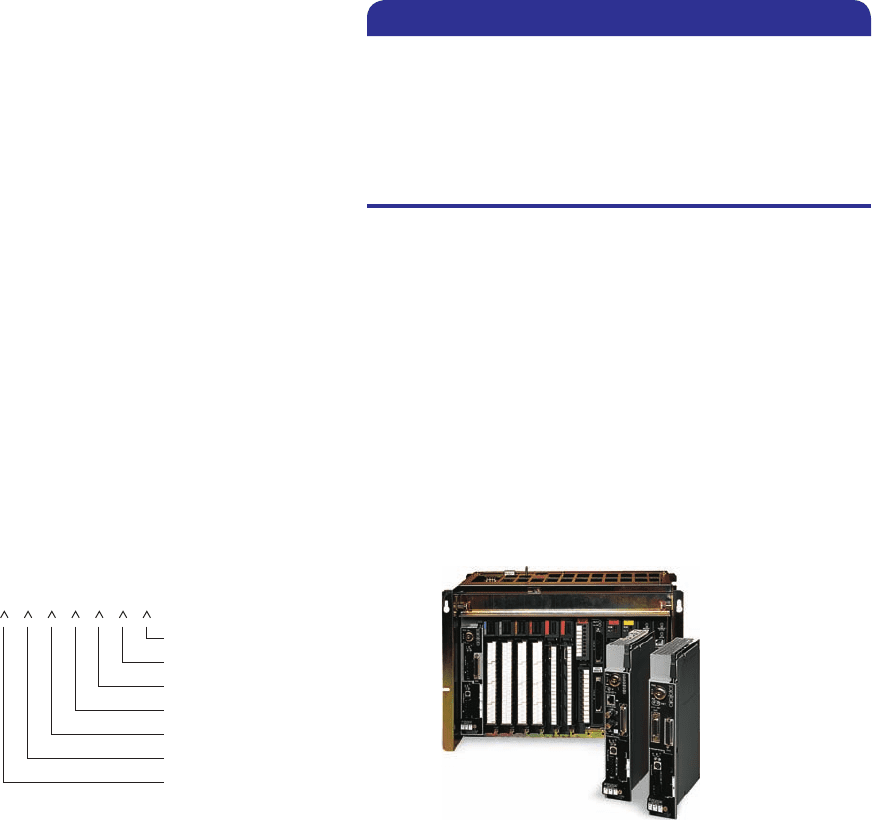
wiring. I/O modules can be 8, 16, 32, or 64 point cards
( Figure2-11 ). The number refers to the number of inputs
or outputs available. The standard I/O module has eight
inputs or outputs. A high-density module may have up to
64 inputs or outputs. The advantage with the high-density
module is that it is possible to install up to 64 inputs or
outputs in one slot for greater space savings. The only dis-
advantage is that the high-density output modules cannot
handle as much current per output.
examples of SLC 500 real-world general input and output
addresses:
Figure 2-5 Allen-Bradley SLC 500 rack/slot-based addressing format.
Source: Image Used with Permission of Rockwell Automation, Inc.
Memory
address
Real-world
address
I 130./:
File type
File number
Element number
Slot number
Module type
Subelement number
For terminals above #15
0 1
Bit number
Terminal number
O:4/15 Output module in slot 4, terminal 15
I:3/8 Input module in slot 3, terminal 8
O:6.0 Output module, slot 6
I:5.0 Input module, slot 5
Every input and output device connected to a discrete
I/O module is addressed to a speci c bit in the PLC’s
memory. A bit is a binary digit that can be either 1 or 0.
Analog I/O modules use a word addressing format, which
allows the entire words to be addressed. The bit part of
the address is usually not used; however, bits of the digital
representation of the analog value can be addressed by the
programmer if necessary. Figure 2-6 illustrates bit level
and word level addressing as it applies to an SLC 500
controller.
Figure2-7 illustrates the Allen-Bradley ControlLogix
tag-based addressing format. With Logix5000 controllers,
you use a tag (alphanumeric name) to address data (vari-
ables). Instead of a xed numeric format the tag name
itself identi es the data. The eld devices are assigned
tag names that are referenced when the PLC ladder logic
program is developed.
PC-based control runs on personal or industrial hard-
ened computers. Also known as soft PLCs, they simulate
the functions of a PLC on a PC, allowing open architecture
systems to replace proprietary PLCs. This implementa-
tion uses an input/output card ( Figure2-8 ) in conjunction
with the PC as an interface for the eld devices.
Combination I/O modules can have both input and out-
put connections in the same physical module as illustrated
pet10882_ch02_017-042.indd 20pet10882_ch02_017-042.indd 20 7/23/10 9:04 PM7/23/10 9:04 PM
PLC Hardware Components Chapter 2 21
Figure 2-6 SLC 500 bit level and word level addressing. ( a ) Bit level
addressing. ( b ) Word level addressing.
1
Inputs
Data files
Program files
Output
I:1/0
0I:1/1
Processor memory
Input
addressing
Output
addressing
I:1/1
I:1/1I:1/0 O:3/0
O:3/0
I:1/0
00:3/0
(a)
Processor
O0:2.0
(address)
Meter
analog
output
Thermocouple
analog input
I0:2.0
(address)
0
Analog
module
12
1 2 0
Type Slot
Address
Word Bit Inputs
O 2 0
Type Slot
Address
Word Bit
0
1
Outputs
0
1
Not used
Not used
IN 0
IN 0
OUT 0
OUT 0
Output Input
Power
Analog
2:
2
0
(b)
Figure 2-7 Allen-Bradley ControlLogix tag-based addressing format.
Source: Image Used with Permission of Rockwell Automation, Inc.
Start
I_PBO
<Local:6:1.Data.0>
Input instruction
Base address
Alias tag pointing
to base address
Description assigned
to alias tag
pet10882_ch02_017-042.indd 21pet10882_ch02_017-042.indd 21 7/27/10 10:41 PM7/27/10 10:41 PM
22 Chapter 2 PLC Hardware Components
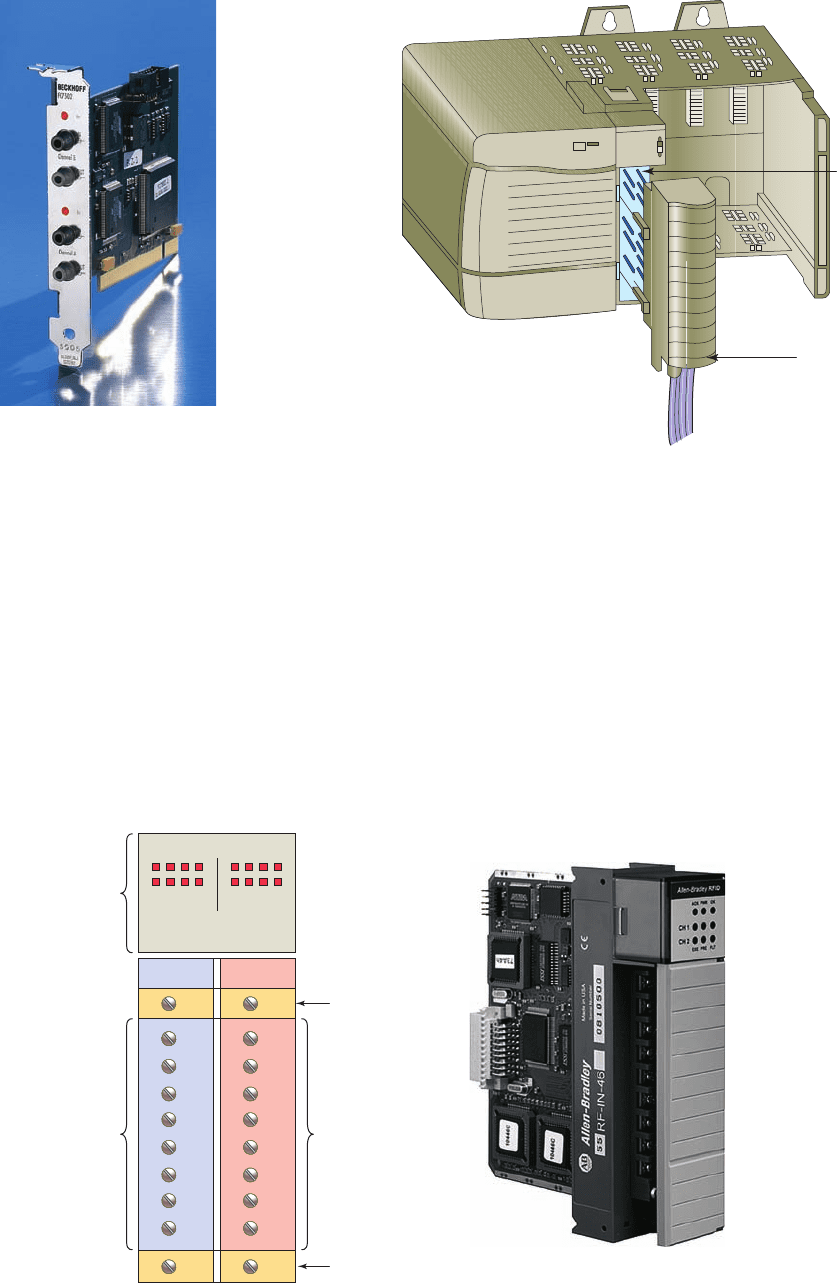
Figure 2-9 Typical combination I/O module.
Source: Image Used with Permission of Rockwell Automation, Inc.
0
1
2
3
4
5
6
7
Status
Inputs
Status
indicators
Input Output
Input
connections
Output
connections
0
1
2
3
4
5
6
7
Outputs
Power supply
connections
Power supply
connections
Figure 2-10 Plug-in terminal block.
Terminal
block
Module
Figure 2-8 Typical PC interface card.
Source: Photo © Beckhoff Automation GmbH.
2.2 Discrete I/O Modules
The most common type of I/O interface module is the dis-
crete type ( Figure 2-12 ). This type of interface connects
eld input devices of the ON/OFF nature such as selec-
tor switches, pushbuttons, and limit switches. Likewise,
output control is limited to devices such as lights, relays,
solenoids, and motor starters that require simple ON/OFF
switching. The classi cation of discrete I/O covers bit-
oriented inputs and outputs. In this type of input or output,
each bit represents a complete information element in itself
and provides the status of some external contact or advises
of the presence or absence of power in a process circuit.
Each discrete I/O module is powered by some eld-
supplied voltage source. Since these voltages can be of
different magnitude or type, I/O modules are available at
various AC and DC voltage ratings, as listed in Table 2-1.
pet10882_ch02_017-042.indd 22pet10882_ch02_017-042.indd 22 7/23/10 9:04 PM7/23/10 9:04 PM