Petruzella F.D. Programmable Logic Controllers
Подождите немного. Документ загружается.


Number Systems and Codes Chapter 3 53
and subtrahend. The result of the subtraction process is
called the difference, represented as:
A (minuend)
2B (subtrahend)
C (difference)
To subtract from larger binary numbers, subtract col-
umn by column, borrowing from the adjacent column
when necessary. Remember that when borrowing from
the adjacent column, there are now two digits, i.e., 0 bor-
row 1 gives 10.
The procedure for subtracting numbers using the 1’s
complement is as follows:
Step 1 Change the subtrahend to 1’s complement.
Step 2 Add the two numbers.
Step 3 Remove the last carry and add it to the number
(end-around carry).
Decimal Binary
10 1010 1010
2 6 20110 11001
4 100 10011
11
100
When there is a carry at the end of the result, the result
is positive. When there is no carry, then the result is nega-
tive and a minus sign has to be placed in front of it.
End-around carry
1’s complement
Subtract 1001 from 1101.
1101
21001
0100
Subtract 0111 from 1011.
1011
20111
0100
EXAMPLE
Binary numbers can also be negative. The procedure
for this calculation is identical to that of decimal numbers
because the smaller value is subtracted from the larger
value and a negative sign is placed in front of the result.
Subtract 111 from 100.
111
2100
2011
Subtract 11011 from 10111.
11011
210111
200100
EXAMPLE
There are other methods available for doing subtraction:
1’s complement
2’s complement
Subtract 11011 from 01101.
01101
1 2 00100 The 1’s complement
10001 There is no carry,
so we take the 1’s
complement and add
the minus sign:
201110
EXAMPLE
For subtraction using the 2’s complement, the 2’s com-
plement is added instead of subtracting the numbers. In
the result, if the carry is a 1, then the result is positive; if
the carry is a 0, then the result is negative and requires a
minus sign.
Subtract 101 from 111.
111
1 2 011 The 2’s complement
1010 The rst 1 indicates that
the result is positive, so it
is disregarded:
010
EXAMPLE
pet10882_ch03_043-056.indd 53pet10882_ch03_043-056.indd 53 7/23/10 9:09 PM7/23/10 9:09 PM

54 Chapter 3 Number Systems and Codes
Binary numbers are multiplied in the same manner
as decimal numbers. When multiplying binary numbers,
there are only four conditions that can occur:
0 3 0 5 0
0 3 1 5 0
1 3 0 5 0
1 3 1 5 1
To multiply numbers with more than one digit, form
partial products and add them together, as shown in the
following example.
Decimal Equivalent binary
5 101
36 3110
30 000
101
101
11110
The process for dividing one binary number by an-
other is the same for both binary and decimal numbers, as
shown in the following example.
Decimal Equivalent binary
7 111
2
q
_
14 10
q
_
1110
10
11
10
10
10
00
The basic function of a comparator is to compare the
relative magnitude of two quantities. PLC data compari-
son instructions are used to compare the data stored in
two words (or registers). At times, devices may need to
be controlled when they are less than, equal to, or greater
than other data values or set points used in the applica-
tion, such as timer and counter values. The basic compare
instructions are as follows:
A 5 B (A equals B)
A . B (A is greater than B)
A , B (A is less than B)
Subtract 101 from 111.
111
1 2 011 The 2’s complement
1010 The rst 1 indicates that
the result is positive, so it
is disregarded:
010
EXAMPLE
pet10882_ch03_043-056.indd 54pet10882_ch03_043-056.indd 54 7/23/10 9:09 PM7/23/10 9:09 PM

Number Systems and Codes Chapter 3 55
1. Convert each of the following binary numbers to
decimal numbers:
a. 1 0
b. 100
c. 111
d. 1011
e. 1100
f. 10010
g. 10101
h. 11111
i. 11001101
j. 11100011
2. Convert each of the following decimal numbers to
binary numbers:
a. 7
b. 1 9
c. 2 8
d. 4 6
e. 5 7
f. 8 6
g. 9 4
h. 112
i. 148
j. 230
3. Convert each of the following octal numbers to
decimal numbers:
a. 3 6
b. 104
c. 120
d. 216
e. 360
f. 1516
4. Convert each of the following octal numbers to
binary numbers:
a. 7 4
b. 130
c. 250
d. 1510
e. 2551
f. 2634
5. Convert each of the following hexadecimal num-
bers to decimal numbers:
a. 5 A
b. C 7
c. 9B5
d. 1A6
6. Convert each of the following hexadecimal num-
bers to binary numbers:
a. 4 C
b. E 8
c. 6D2
d. 31B
7. Convert each of the following decimal numbers to
BCD:
a. 146
b. 389
c. 1678
d.
2502
8.
What is the most important characteristic of the
Gray code?
9. What makes the binary system so applicable to
computer circuits?
10. D e ne the following as they apply to the binary
memory locations or registers:
a. Bit
b. Byte
c. Word
d. LSB
e. MSB
11. State the base used for each of the following num-
ber systems:
a. Octal
b. Decimal
c. Binary
d. Hexadecimal
12. D e ne the term sign bit.
13. Explain the difference between the 1’s complement
of a number and the 2’s complement.
14. What is ASCII code?
15. Why are parity bits used?
16. Add the following binary numbers:
a. 110 1 111
b. 101 1 011
c. 1100 1 1011
17. Subtract the following binary numbers:
a. 1101 2 101
b. 1001 2 110
c. 10111 2 10010
CHAPTER 3 REVIEW QUESTIONS
pet10882_ch03_043-056.indd 55pet10882_ch03_043-056.indd 55 7/23/10 9:09 PM7/23/10 9:09 PM
56 Chapter 3 Number Systems and Codes
19. Divide the following unsigned binary numbers:
a. 1010 4 10
b. 1100 4 11
c. 110110 4 1 0
18. Multiply the following binary numbers:
a. 110 3 110
b. 010 3 101
c. 101 3 11
1. The following binary PLC coded information is to
be programmed using the hexadecimal code. Convert
each piece of binary information to the appropriate
hexadecimal code for entry into the PLC from the
keyboard.
a. 0001 1111
b. 0010 0101
c. 0100 1110
d. 0011 1001
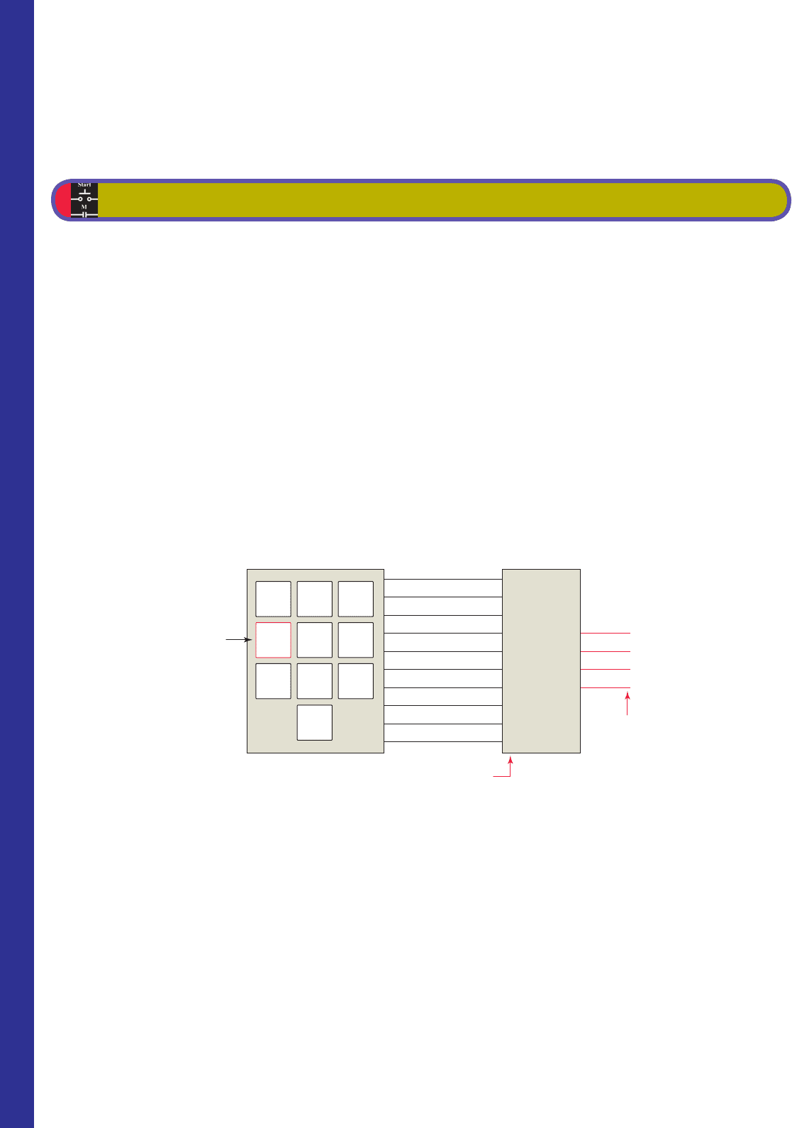
2. The encoder circuit shown in Figure 3-17 is used
to convert the decimal digits on the keyboard to a
binary code. State the output status (HIGH/LOW) of
A-B-C-D when decimal number
a. 2 is pressed.
b. 5 is pressed.
CHAPTER 3 PROBLEMS
c. 7 is pressed.
d. 8 is pressed.
3. If the bits of a 16-bit word or register are numbered
according to the octal numbering system, beginning
with 00, what consecutive numbers would be used to
represent each of the bits?
4. Express the decimal number 18 in each of the fol-
lowing number codes:
a. Binary
b. Octal
c. Hexadecimal
d. BCD
Figure 3-17 Diagram for Problem 2.
Decimal
number
pressed
Binary-coded
0100 output
High
High
Lo
w
Low
Low
Encoder
A
B
C
D
4 input
High
789
4 56
12
0
3
0
1
2
3
4
5
6
7
8
9
pet10882_ch03_043-056.indd 56pet10882_ch03_043-056.indd 56 7/23/10 9:09 PM7/23/10 9:09 PM
57
4
Fundamentals of Logic
This chapter gives an overview of digital logic
gates and illustrates how to duplicate this type
of control on a PLC. Boolean algebra, which is a
shorthand way of writing digital gate diagrams,
is discussed briefl y. Some small hand-held pro-
grammers have digital logic keys, such as AND,
OR, and NOT, and are programmed using Bool-
ean expressions.
Chapter Objectives
After completing this chapter, you will be able to:
4.1 Describe the binary concept and the functions of gates
4.2 Draw the logic symbol, construct a truth table, and
state the Boolean equation for the AND, OR, and NOT
functions
4.3 Construct circuits from Boolean expressions and derive
Boolean equations for given logic circuits
4.4 Convert relay ladder schematics to ladder logic
programs
4.5 Develop elementary programs based on logic gate
functions
4.6 Program instructions that perform logical operations
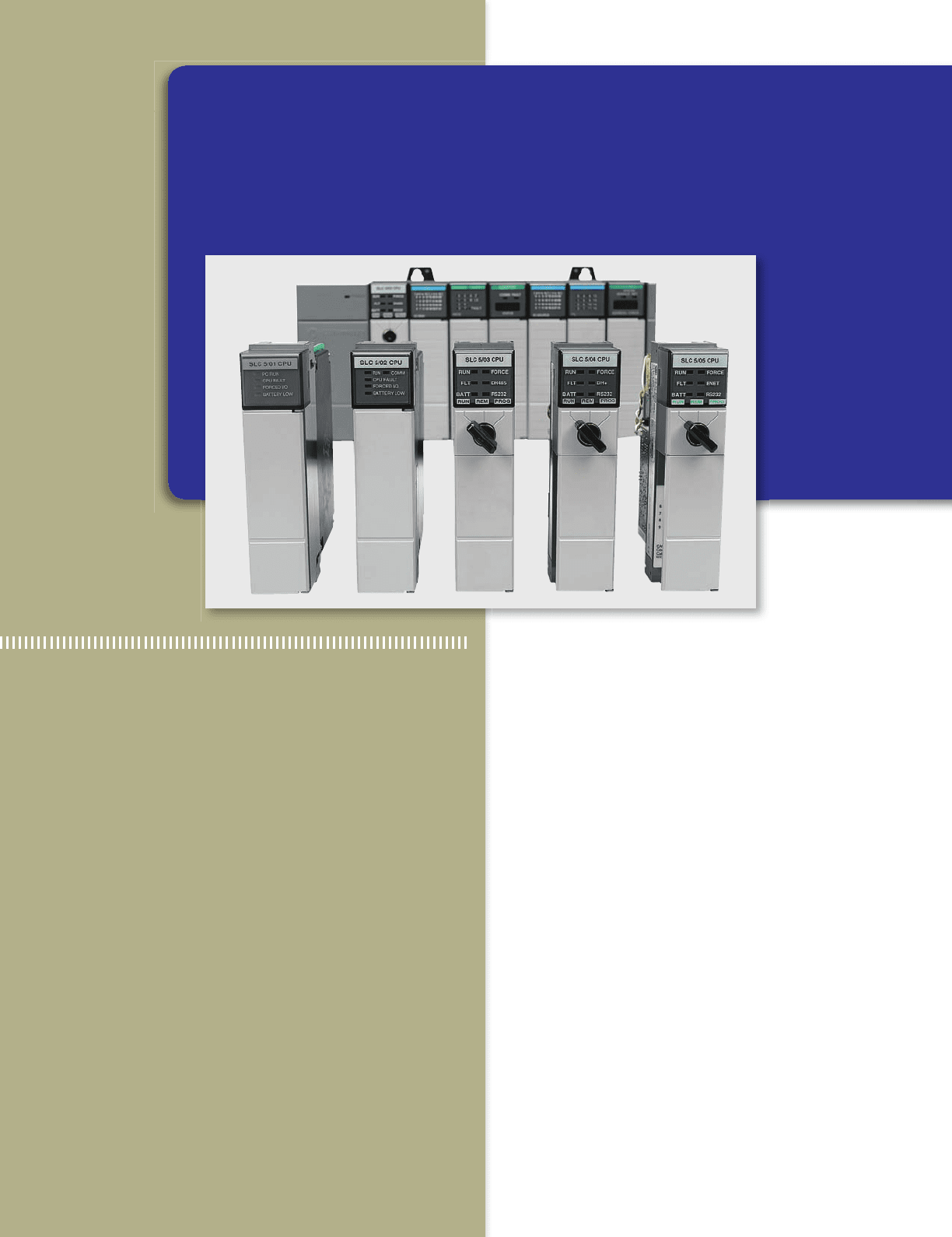
Image Used with Permission of Rockwell Automation, Inc.
pet10882_ch04_057-070.indd 57pet10882_ch04_057-070.indd 57 7/23/10 9:12 PM7/23/10 9:12 PM
58 Chapter 4 Fundamentals of Logic
the outcome and a symbol that represents the operation.
For the purpose of this discussion, the outcome or out-
put is called Y and the signal inputs are called A, B, C,
and so on. Also, binary 1 represents the presence of a
signal or the occurrence of some event, and binary 0
represents the absence of the signal or nonoccurrence
of the event.
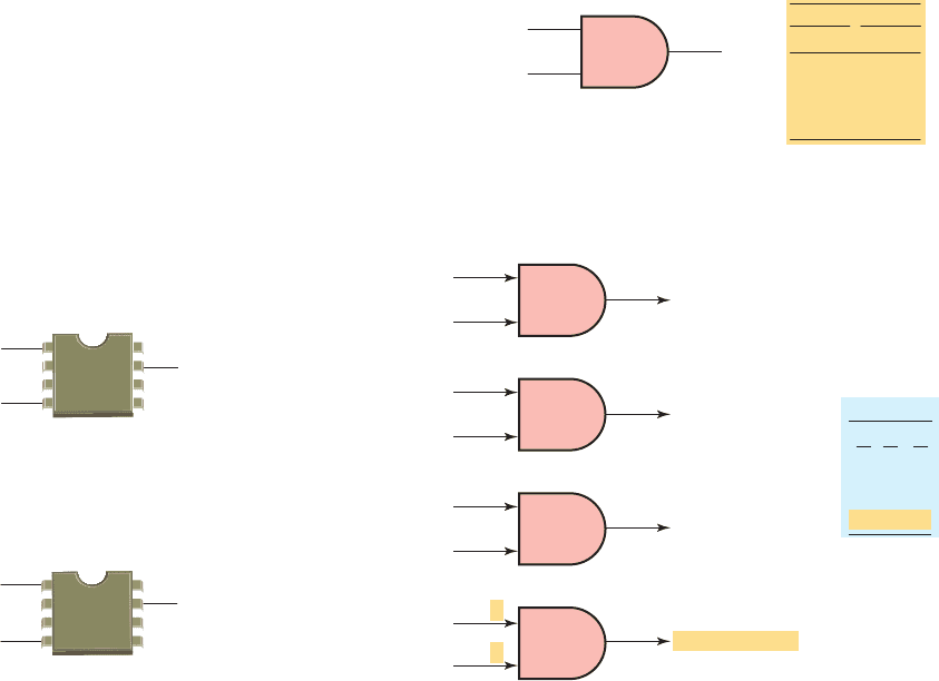
The AND Function
The symbol drawn in Figure 4-3 is that of an AND gate.
An
AND gate is a device with two or more inputs and
one output. The AND gate output is 1 only if all in-
puts are 1. The AND truth table in Figure 4-3 shows
the resulting output from each of the possible input
combinations.
Logic gate truth tables show each possible input to the
gate or circuit and the resultant output depending upon the
combination of the input(s).
Since logic gates are digital ICs (Integrated Circuits)
their input and output signals can be in only one of two
possible digital states, i.e., logic 0 or logic 1. Thus, the
logic state of the output of a logic gate depends on the
logic states of each of its individual inputs. Figure 4-4
4.1 The Binary Concept
The PLC, like all digital equipment, operates on the bi-
nary principle. The term binary principle refers to the idea
that many things can be thought of as existing in only one
of two states. These states are 1 and 0. The 1 and 0 can
represent ON or OFF, open or closed, true or false, high or
low, or any other two conditions. The key to the speed and
accuracy with which binary information can be processed
is that there are only two states, each of which is distinctly
different. There is no in-between state so when informa-
tion is processed the outcome is either yes or no.
A logic gate is a circuit with several inputs but only
one output that is activated by particular combinations of
input conditions. The two-state binary concept, applied
to gates, can be the basis for making decisions. The high
beam automobile lighting circuit of Figure4-1 is an ex-
ample of a logical AND decision. For this application,
the high beam light can be turned on only when the light
switch AND the high beam switch are closed.
The dome light automobile circuit of Figure 4-2 is an
example of a logical OR decision. For this application, the
dome light will be turned on whenever the passenger door
switch OR the driver door switch is activated.
Logic is the ability to make decisions when one or
more different factors must be taken into account before
an action is taken. This is the basis for the operation of
the PLC, where it is required for a device to operate when
certain conditions have been met.
4.2 AND, OR, and NOT Functions
The operations performed by digital equipment are
based on three fundamental logic functions: AND, OR,
and NOT. Each function has a rule that will determine
Figure 4-1 The logical AND.
High beam
light
Light switch
High beam
switch
In
p
uts Out
p
ut
AND
Figure 4-2 The logical OR.
Dome light
Passenger
door switch
Driver
door switch
Inputs Output
AND
Figure 4-3 AND gate.
A
B
Output
Y
Two-input AND
gate symbol
Inputs
0
0
1
1
0
1
0
1
0
0
0
1
AB Y
Inputs
AND truth table
Output
Figure 4-4 AND logic gate digital signal states.
Truth table
0
0
1
1
A
0
1
0
1
B
0
0
0
1
Y
1
Output (Y ) 1
1
0
Output (Y ) 0
0
1
Output (Y ) 0
0
0
Output (Y ) 0
1
B
A
B
A
B
A
B
A
pet10882_ch04_057-070.indd 58pet10882_ch04_057-070.indd 58 7/23/10 9:12 PM7/23/10 9:12 PM
Fundamentals of Logic Chapter 4 59
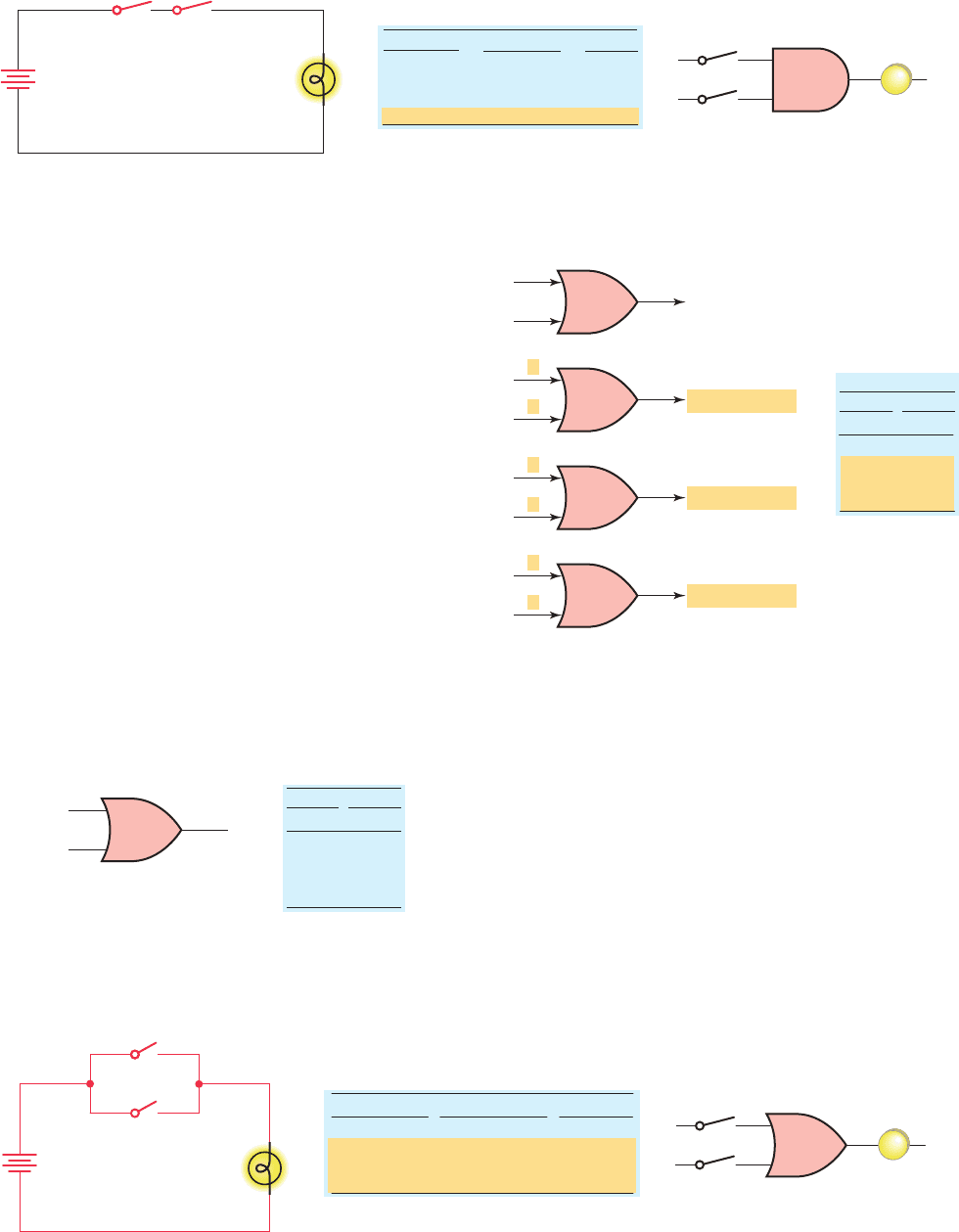
Figure 4-7 illustrates the four possible combinations of
inputs for a 2-input OR gate. The basic rules that apply to
an OR gate are:
• If one or more inputs are 1, the output is 1.
• If all inputs are 0, the output will be 0.
The OR logic gate operates similarly to control devices
connected in parallel, as illustrated in Figure 4-8 . The
light will be on if switch A or switch B or both are closed.
illustrates the four possible combinations of inputs for a
2-input AND gate. The basic rules that apply to an AND
gate are:
• If all inputs are 1, the output will be 1.
• If any input is 0, the output will be 0.
The AND logic gate operates similarly to control de-
vices connected in series, as illustrated in Figure 4-5 . The
light will be on only when both switch A and switch B
are closed.
The OR Function
The symbol drawn in Figure 4-6 is that of an OR gate.
An OR gate can ha
ve any number of inputs but only one
output. The OR gate output is 1 if one or more inputs are
1. The truth table in Figure 4-6 shows the resulting output
Y from each possible input combination.
Figure 4-5 AND logic gate operates similarly to control devices connected in series.
Truth table
SW-
Open
Open
Closed
Closed
(0)
(0)
(1)
(1)
Open
Closed
Open
Closed
(0)
(1)
(0)
(1)
SW-A
B Light
Off
Off
Off
On
(0)
(0)
(0)
(1)
Hardwired circuit
Light
SW-A SW-B
SW-A
Light
SW-B
Logic representation
Figure 4-6 OR gate.
0
0
1
1
0
1
0
1
0
1
1
1
AB Y
Inputs
Output
OR truth table
B
Output
Y
Inputs
Two-input OR
gate symbol
A
Figure 4-7 OR logic gate digital signal states.
ABY
Inputs
Output
Truth table
0
0
1
1
0
1
0
1
0
1
1
1
1
1
Output (Y ) = 0
Output (Y ) = 1
Output (Y ) = 1
Output (Y ) = 1
B
A
1
0
B
A
0
1
B
A
0
0
B
A
Figure 4-8 OR logic gate operates similarly to control devices connected in parallel.
Open
Open
Closed
Closed
(0)
(0)
(1)
(1)
Open
Closed
Open
Closed
(0)
(1)
(0)
(1)
Off
On
On
On
(0)
(1)
(1)
(1)
SW-A SW-B Light
Truth table
Hardwired circuit
SW-B
SW-A
Light
Logic representation
SW-A
Light
SW-B
pet10882_ch04_057-070.indd 59pet10882_ch04_057-070.indd 59 7/23/10 9:12 PM7/23/10 9:12 PM
60 Chapter 4 Fundamentals of Logic
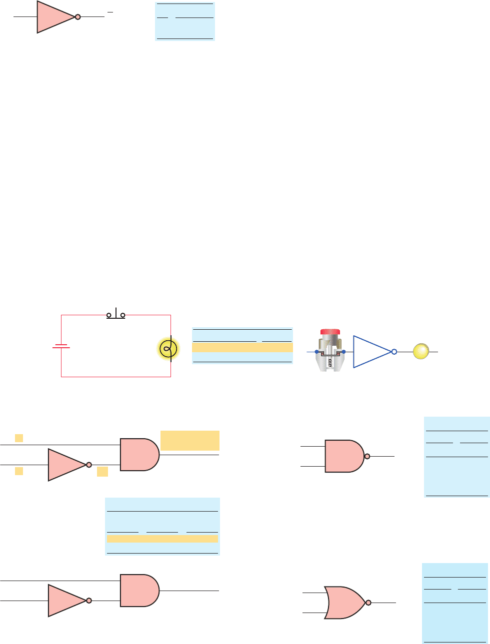
The NOT Function
The symbol drawn in Figure 4-9 is that of a NOT func-
tion. Unlik
e the AND and OR functions, the NOT func-
tion can have only one input. The NOT output is 1 if the
input is 0. The output is 0 if the input is 1. The result
of the NOT operation is always the inverse of the input,
and the NOT function is, therefore, called an inverter. The
NOT function is often depicted by using a bar across the
top of the letter, indicating an inverted output. The small
circle at the output of the inverter is termed a state indica-
tor and indicates that an inversion of the logical function
has taken place.
The logical NOT function can be performed on a con-
tact input simply by using a normally closed instead of
a normally open contact. Figure 4-10 shows an example
Figure 4-9 NOT function.
OutputInput
A
0
1
NOT A
1
0
NOT truth table
A
A (NOT A)
Figure 4-10 NOT function constructed using a normally closed pushbutton.
Light
Not pressed
Pressed
On
Off
(1)
(0)
(0)
(1)
Truth table Logic representation
Hardwired circuit
Pushbutton
N.C. pushbutton
Light
Single input
Light
Figure 4-11 NOT function is most often used in
conjunction with an AND gate.
Low-pressure
indicator off (0)
(0)
(Pressure
switch closed)
(Power on)
Low-pressure
indicator on (1)
(1)
A 1
B 1
(Pressure
switch open)
(Power on)
Pressure
switch
Power
Pressure
indicator
0
1
1
1
1
0
Truth table
A 1
B 0
Figure 4-12 NAND gate symbol and truth table.
Inputs Output
0
0
1
1
0
1
0
1
1
1
1
0
NAND truth table
AB Y
Output
Inputs
Two-input
NAND gate
B
Y
A
Figure 4-13 NOR gate symbol and truth table.
Inputs Output
0
0
1
1
0
1
0
1
1
0
NOR truth table
0
0
AB Y
Output
Inputs
Two-input
NOR gate
B
Y
A
of the NOT function constructed using a normally closed
pushbutton in series with a lamp. When the input pushbut-
ton is not actuated, the output lamp is ON. When the input
pushbutton is actuated, the output lamp switches OFF.
The NOT function is most often used in conjunction
with the AND or the OR gate. Figure 4-11 shows the NOT
function connected to one input of an AND gate for a low-
pressure indicator circuit. If the power is on (1) and the
pressure switch is not closed (0), the warning light will
be on (1).
The NOT symbol placed at the output of an AND gate
would invert the normal output result. An AND gate with
an inverted output is called a NAND gate. The NAND
gate symbol and truth table are shown in Figure 4-12 . The
NAND function is often used in integrated circuit logic
arrays and can be used in programmable controllers to
solve complex logic.
The same rule about inverting the normal output result
applies if a NOT symbol is placed at the output of the OR
gate. The normal output is inverted, and the function is re-
ferred to as a NOR gate. The NOR gate symbol and truth
table are shown in Figure 4-13 .
pet10882_ch04_057-070.indd 60pet10882_ch04_057-070.indd 60 7/23/10 9:12 PM7/23/10 9:12 PM
Fundamentals of Logic Chapter 4 61
only when one input or the other is HIGH, but not both.
The exclusive-OR gate is commonly used for the com-
parison of two binary numbers.
4.3 Boolean Algebra
The mathematical study of the binary number system and
logic is called Boolean algebra. The purpose of this al-
gebra is to provide a simple way of writing complicated
combinations of logic statements. There are many appli-
cations where Boolean algebra could be applied to solv-
ing PLC programming problems.
A typical Boolean instruction list (also referred to as
a statement list) is shown in Table 4-1 . The instructions
The Exclusive-OR (XOR) Function
An often-used combination of gates is the exclusive-OR
(XOR) function.
The XOR gate symbol and truth table are
shown in Figure 4-14 . The output of this circuit is HIGH
Figure 4.14 The XOR gate symbol and truth table.
Truth table
Inputs Output
0
0
1
1
0
1
0
1
0
1
0
1
A
B
Y
Output
Inputs
B
Y
A
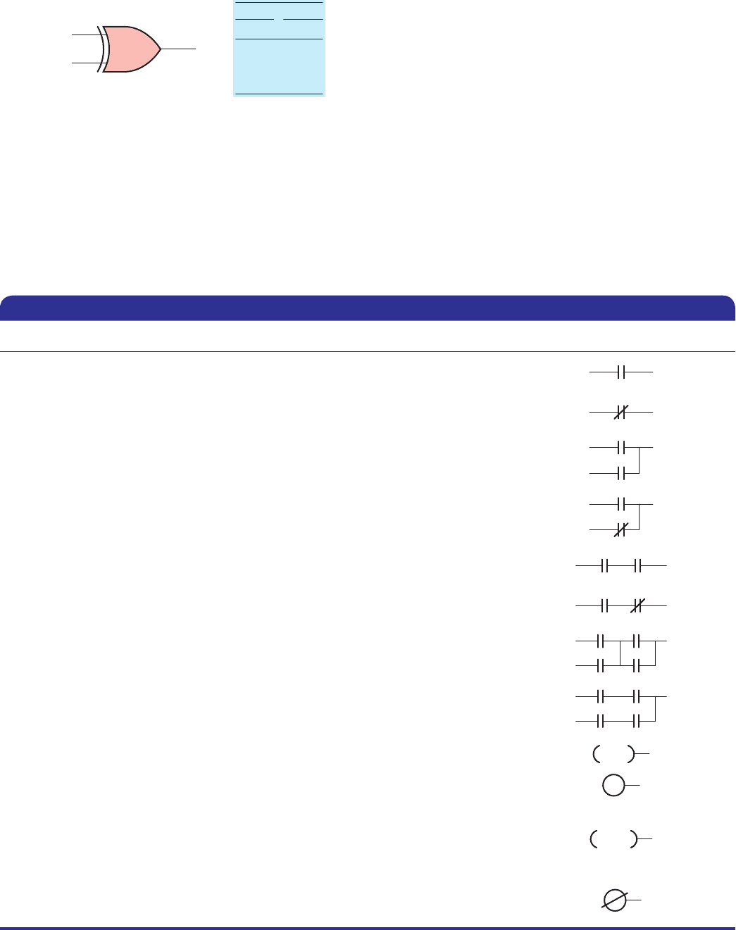
Boolean Instruction and Function Graphic Symbol
Store (STR)–Load (LD)
Begins a new rung or an additional branch in a rung with a normally open contact.
Store Not (STR NOT)–Load Not (LD NOT)
Begins a new rung or an additional branch in a rung with a normally closed contact.
Or (OR)
Logically ORs a normally open contact in parallel with another contact in a rung.
Or Not (OR NOT)
Logically ORs a normally closed contact in parallel with another contact in a rung.
And (AND)
Logically ANDs a normally open contact in series with another contact in a rung.
And Not (AND NOT)
Logically ANDs a normally closed contact in series with another contact in a rung.
And Store (AND STR)–And Load (AND LD)
Logically ANDs two branches of a rung in series.
Or Store (OR STR)–Or Load (OR LOAD)
Logically ORs two branches of a rung in parallel.
Out (OUT)
Re ects the status of the rung (on/off) and outputs the discrete (ON/OFF) state to
the speci ed image register point or memory location.
OUT
Or Out (OR OUT)
Re ects the status of the rung and outputs the discrete (ON/OFF) state to the
image register. Multiple OR OUT instructions referencing the same discrete point
can be used in the program.
OROUT
Output Not (OUT NOT)
Re ects the status of the rung and turns the output OFF for an ON execution
condition; turns the output ON for an OFF execution condition.
Table 4-1 Typical Boolean Instruction or Statement List
pet10882_ch04_057-070.indd 61pet10882_ch04_057-070.indd 61 7/23/10 9:12 PM7/23/10 9:12 PM
62 Chapter 4 Fundamentals of Logic
NOT functions. Inputs are represented by capital letters
A, B, C, and so on, and the output by a capital Y. The
multiplication sign (3) or dot (
•) represents the AND
operation, an addition sign (1) represents the OR op-
eration, the circle with an addition sign ! represents
the exclusive-OR operation, and a bar over the letter
__
A
represents the NOT operation. The Boolean equations
are used to express the mathematical function of the
logic gate .
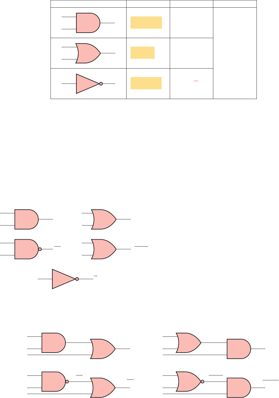
PLC digital systems may be designed using Boolean
algebra. Circuit functions are represented by Boolean
equations. Figure 4-16 illustrates how logic operators
AND, NAND, OR, NOR, and NOT are used singly to
form logical statements. Figure 4-17 illustrates how basic
logic operators are used in combination to form Boolean
equations.
An understanding of the technique of writing simpli-
ed Boolean equations for complex logical statements
is a useful tool when creating PLC control programs.
Some laws of Boolean algebra are different from those
of ordinary algebra. These three basic laws illustrate
the close comparison between Boolean algebra and
Figure 4-15 Boolean algebra as related to AND, OR, and NOT functions.
Logic symbol Logic statement Boolean equation Boolean notations
A
B
A
B
AY
Y
Y Y A B
Y A
Y A • B
or
Y AB
Y is 1 if
A and B are 1
Y is 1 if
A or B is 1
Y is 1 if A is 0
Y is 0 if A is 1
Symbol
•
Meaning
and
or
not
in
vert
result in
AB
AB
Y AB C
A B
Y (A B) C
A B
Y (A B) C
A
B
C
AND
AND
AND
NAND
OR
OR
NOR
Y AB C
A
B
C
OR
A
B
C
A
B
C
Figure 4-17 Logic operators used in combination to form Boolean equations.
are based on the basic Boolean operators of AND, OR,
and NOT. Although these instructions are programmed
in list format similar to BASIC and other text lan-
guages, they implement the same logic as relay ladder
logic.
Figure 4-15 summarizes the basic operators of Bool-
ean algebra as they relate to the basic AND, OR, and
A
B
A
B
A
B
A
B
AB
AB
A
B
A + B
NOT
AA
AND
NAND
OR
NOR
Figure 4-16 Logic operators used singly to form logical
statements.
pet10882_ch04_057-070.indd 62pet10882_ch04_057-070.indd 62 7/23/10 9:12 PM7/23/10 9:12 PM