Petruzella F.D. Programmable Logic Controllers
Подождите немного. Документ загружается.

Fundamentals of Logic Chapter 4 63
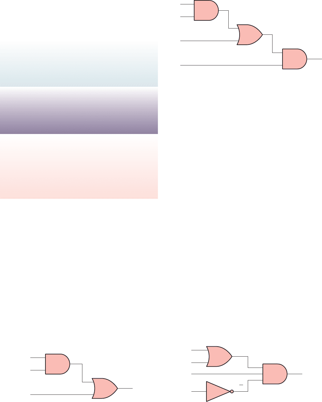
Figure 4-19 shows a logic gate circuit developed from
the Boolean expression Y 5 A(BC 1 D). The procedure
is as follows:
Boolean expression: Y 5 A(BC 1 D)
Gates required: (by inspection)
1 - AND gate with input B and C
1 - OR gate with inputs B, C, and D
1 - AND gate with inputs A and the output from
the OR gate
4.5 Producing the Boolean Equation
for a Given Logic Gate Circuit
A simple logic gate is quite straightforward in its opera-
tion. However, by grouping these gates into combinations,
it becomes more dif cult to determine which combina-
tions of inputs will produce an output. The Boolean equa-
tion for the logic circuit of Figure 4-20 is determined as
follows:
• The output of the OR gate is A 1 B
• The output of the inverter is D
–
• Based on the input combination applied to the AND
gate the Boolean equation for the circuit is Y 5 C
D
–
(A 1B)
4.4 Developing Logic Gate Circuits
from Boolean Expressions
As logic gate circuits become more complex, the need to
express these circuits in Boolean form becomes greater.
Figure 4-18 shows a logic gate circuit developed from the
Boolean expression Y 5 AB 1 C. The procedure is as
follows:
Boolean expression: Y 5 AB 1 C
Gates required: (by inspection)
1 - AND gate with input A and B
1 - OR gate with input C and output from previous
AND gate
A
B
C
Inputs
Output
Y
Figure 4-18 Logic gate circuit developed from the Boolean
expression Y 5 AB 1 C.
B
C
D
Output
Y
A
Inputs
Figure 4-19 Logic gate circuit developed from the Boolean
expression Y 5 A(BC 1 D).
COMMUTATIVE LAW
A 1 B 5 B 1 A
A ? B 5 B ? A
ASSOCIATIVE LAW
(A 1 B) 1 C 5 A 1 (B 1 C )
(A ? B) ? C 5 A ? (B ? C )
DISTRIBUTIVE LAW
A ? (B 1 C) 5 (A ? B) 1 (A ? C )
A 1 (B ? C) 5 (A 1 B) ? (A 1 C )
This la
w holds true only in
Boolean algebra.
ordinary algebra, as well as one major difference be-
tween the two:
Output
Inputs
C
D
Y
A
B
C
D
A B
Figure 4-20 Determining the Boolean equation for a logic
circuit.
pet10882_ch04_057-070.indd 63pet10882_ch04_057-070.indd 63 7/23/10 9:12 PM7/23/10 9:12 PM
64 Chapter 4 Fundamentals of Logic
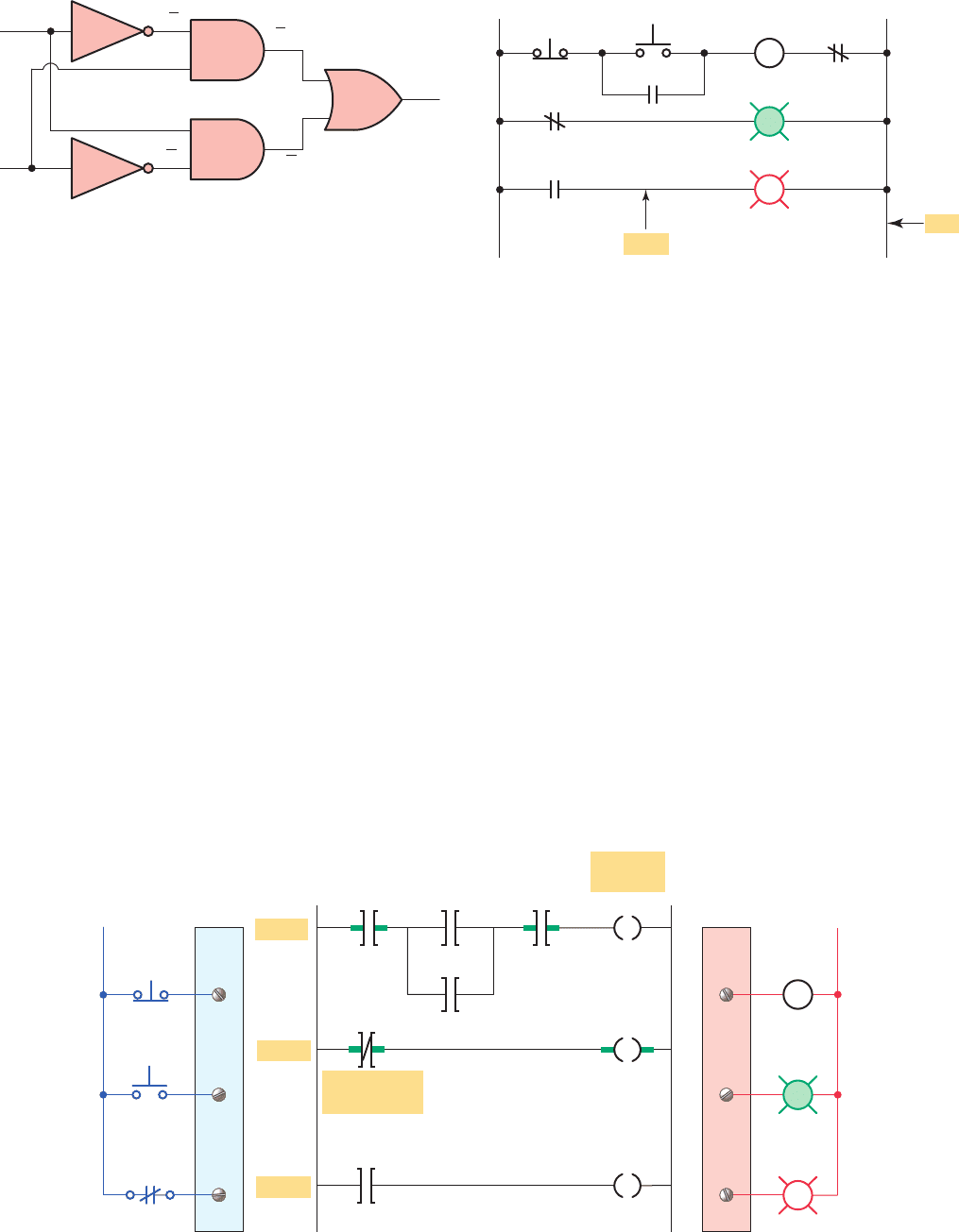
called rails or legs, connecting the two power lines with
what look like rungs of a ladder—thus the name, relay
ladder schematic.
Hardwired logic is xed; it is changeable only by al-
tering the way devices are electrically interconnected.
In contrast, programmable control is based on the basic
logic functions, which are programmable and easily
changed. These functions (AND, OR, NOT) are used ei-
ther singly or in combinations to form instructions that
will determine if a device is to be switched on or off.
The form in which these instructions are implemented to
convey commands to the PLC is called the language . The
most common PLC language is ladder logic . Figure 4-23
shows a typical ladder logic program for the motor start/
stop circuit. The instructions used are the relay equiva-
lent of normally open (NO) and normally closed (NC)
contacts and coils.
PLC contact symbolism is a simple way of expressing
the control logic in terms of symbols. These symbols are
The Boolean equation for the logic circuit of Fig-
ure4-21 is determined as follows:
• The output of AND gate 1 is A
–
B
• The output of AND gate 2 is AB
–
• Based on the combination of inputs applied to the
OR gate the Boolean equation for the circuit is
Y5A
–
B 1 AB
–
4.6 Hardwired Logic versus
Programmed Logic
The term hardwired logic refers to logic control functions
that are determined by the way devices are electrically in-
terconnected. Hardwired logic can be implemented using
relays and relay ladder schematics. Relay ladder sche-
matics are universally used and understood in industry.
Figure 4-22 shows a typical relay ladder schematic of a
motor stop/start control station with pilot lights. The con-
trol scheme is drawn between two vertical supply lines.
All the components are placed between these two lines,
Inputs
Output
B
Y
A
AB
AB
B
A
1
2
Figure 4-21 Determining the Boolean equation for a logic
circuit.
Figure 4-22 Motor stop/start relay ladder schematic.
STOP
START
M
M
M
L2
L1
Rung
Rail
OL
R
G
M
Input
module
Output
module L2
STOP
STOP
START
PROGRAM
START
Relay contact
equivalent
Rung 1
Rung 2
Rung 3
Relay coil
equivalent
OL
OL
M
M
M
M
G
R
L1
R
G
M
Figure 4-23 Motor stop/start ladder logic program.
pet10882_ch04_057-070.indd 64pet10882_ch04_057-070.indd 64 7/23/10 9:12 PM7/23/10 9:12 PM
Fundamentals of Logic Chapter 4 65
Because the PLC uses ladder logic diagrams, the con-
version from any existing relay logic to programmed
logic is simpli ed. Each rung is a combination of input
conditions (symbols) connected from left to right, with
the symbol that represents the output at the far right. The
symbols that represent the inputs are connected in series,
parallel, or some combination of the two to obtain the de-
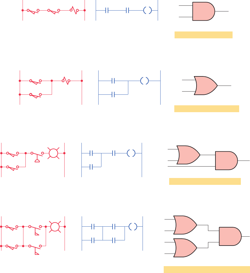
sired logic. The following group of examples illustrates
the relationship between the relay ladder schematic, the
ladder logic program, and the equivalent logic gate circuit.
basically the same as those used for representing hard-
wired relay control circuits. A rung is the contact sym-
bolism required to control an output. Some PLCs allow
a rung to have multiple outputs while others allow only
one output per rung. A complete ladder logic program
then consists of several rungs, each of which controls an
output. In programmed logic all mechanical switch con-
tacts are represented by a software contact symbol and
all electromagnetic coils are represented by a software
coil symbol.
SOL
LS1 LS2
BYA
Relay schematic
Ladder logic program
Inputs
Output
A
B
Y
Gate logic
Boolean equation: AB Y
Example 4-1 Two limit switches connected in series and used to control a solenoid valve.
SOL
LS1
Boolean equation: A B Y
AY
Relay schematic Ladder logic program
Gate logic
LS2
B
Inputs
Output
A
Y
B
Example 4-2 Two limit switches connected in parallel and used to control a solenoid valve.
PSLS1
Boolean equation: (A B)C Y
PL
AC
Relay schematic
Ladder logic program Gate logic
LS2
B
G
Y
Inputs
Output
A B
A
C
Y
B
Example 4-3 Two limit switches connected in parallel with each other and in series with a pressure switch.
FS2
LS1
Boolean equation: (A B) (C D) Y
PL
FS1
Relay schematic Gate logic
LS2
R
Inputs
Output
C D
A B
A
B
C
D
Y
A
B
C
D
Y
Ladder logic program
Example 4-4 Two limit switches connected in parallel with each other and in series with two sets of fl ow
switches (that are connected in parallel with each other), and used to control a pilot light.
pet10882_ch04_057-070.indd 65pet10882_ch04_057-070.indd 65 7/23/10 9:12 PM7/23/10 9:12 PM

66 Chapter 4 Fundamentals of Logic
Boolean equation: (AB) C Y
H
Relay schematic Ladder logic program
Gate logic
LS1
LS2
LS3
A
B
C
Y
Inputs
Y
Output
AB
A
C
B
Example 4-5 Two limit switches connected in series with each other and in parallel with a third limit
switch, and used to control a warning horn.
Boolean equation: (AB) (CD) Y
PL
Relay schematic
Gate logic
LS1
LS3
LS2
LS4
R
A
C
B
D
Y
Ladder logic program
Inputs
Output
A
B
Y
C
D
Example 4-6 Two limit switches connected in series with each other and in parallel with two other limit
switches (that are connected in series with each other), and used to control a pilot light.
PB SOL
Boolean equation: AB Y
Relay schematic Ladder logic program
Gate logic
LS1
A
B
Y
Inputs
Output
A
B
B
Y
Example 4-7 One limit switch connected in series with a normally closed pushbutton and used to control
a solenoid valve. This circuit is programmed so that the output solenoid will be turned on when the limit switch
is closed and the pushbutton is
not pushed.
Relay schematic
Ladder logic program Gate logic
AB
A
B
AB
Boolean equation: AB AB Y
A B Y
Y
Y
Inputs
Output
A
B
Y
Example 4-8 Exclusive-OR circuit. The output lamp of this circuit is ON only when pushbutton A or B is pressed, but not both.
This circuit has been programmed using only the normally open A and B pushbutton contacts as the inputs to the program.
pet10882_ch04_057-070.indd 66pet10882_ch04_057-070.indd 66 7/23/10 9:12 PM7/23/10 9:12 PM
Fundamentals of Logic Chapter 4 67
Relay schematic
Stops
Starts
Ladder logic program
Gate logic
CD
A
B
C D A
B
M
M
Stops
A
B
M
Starts
C
D
M
M
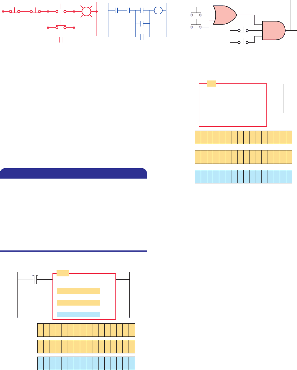
Example 4-9 A motor control circuit with two start/stop buttons. When either start button is depressed, the motor runs.
By use of a seal-in contact, it continues to run when the start button is released. Either stop button stops the motor when it is
depressed.
Figure 4-24 Word-level AND instruction.
Source A
B3:5
Source B
B3:7
Destination
B3:10
1100110011001100
1111111100000000
1100110000000000
Input A
1100110000000000
Destination
1111111100000000
Source B
1100110011001100
BITWISE AND
Source A
AND
B3:10
B3:7
B3:5
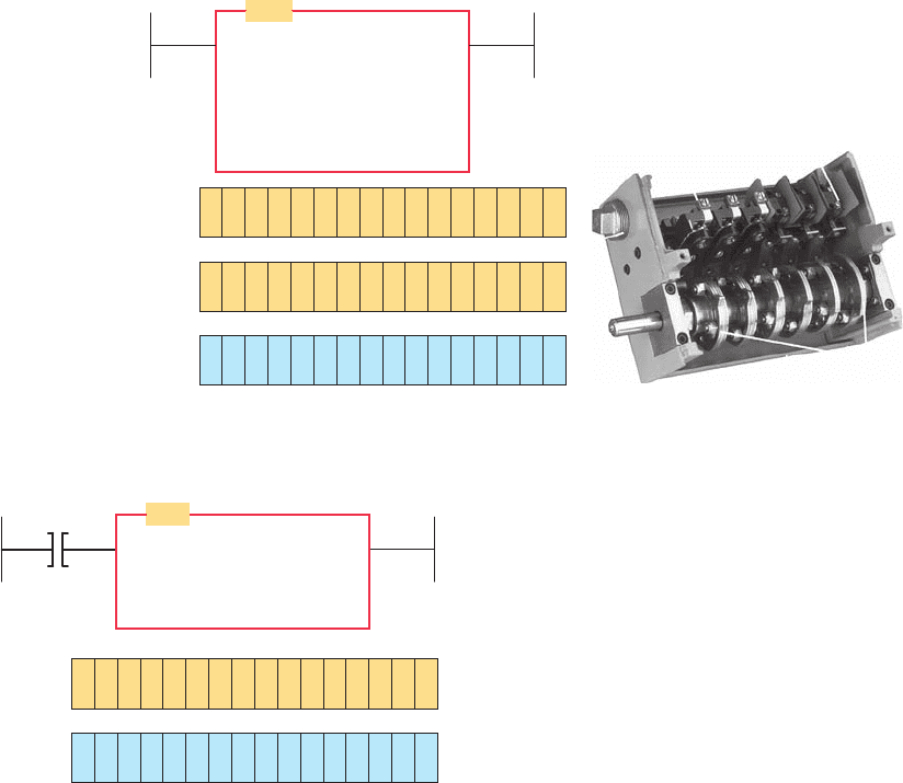
Figure 4-25 Word-level OR instruction.
Source A
B3:1
OR
BITWISE INCLUS OR
Source A B3:1
Source B
Destination
Source B
B3:2
Destination
B3:20
1100110011001100
1111111100000000
1111111111001100
B3:2
B3:20
4.7 Programming Word Level Logic
Instructions
Most PLCs provide word-level logic instructions as part
of their instruction set. Table 4-2 shows how to select the
correct word logic instruction for different situations.
Figure 4-24 illustrates the operation of the AND in-
struction to perform a word-level AND operation using
the bits in the two source addresses. This instruction tells
the processor to perform an AND operation on B3:5 and
B3:7 and to store the result in destination B3:10 when
input device A is true. The destination bits are a result of
the logical AND operation.
Figure 4-25 illustrates the operation of a word-level
OR instruction, which ORs the data in Source A, bit by
bit, with the data in Source B and stores the result at the
destination address. The address of Source A is B3:1,
the address of Source B is B3:2, and the destination
address is B3:20. The instruction may be programmed
conditionally, with input instruction(s) preceding it, or
unconditionally, as shown, without any input instruc-
tions preceding it.
Figure 4-26 illustrates the operation of a word-level
XOR instruction. In this example, data from input I:1.0
are compared, bit by bit, with data from input I:3.0. Any
mismatches energize the corresponding bit in word O:4.0.
As you can see, there is a 1 in every bit location in the
destination corresponding to the bit locations where
SourceA and Source B are different, and a 0 in the des-
tination where Source A and Source B are the same. The
XOR is often used in diagnostics, where real-world in-
puts, such as rotary cam limit switches, are compared
with their desired states.
If you want to...
...use this
instruction.
Know when matching bits in two different
words are both ON
AND
Know when one or both matching bits in two
different words are ON
OR
Know when one or the other bit of matching
bits in two different words is ON
XOR
Reverse the state of bits in a word NOT
Table 4-2 Selecting Logic Instructions
pet10882_ch04_057-070.indd 67pet10882_ch04_057-070.indd 67 7/23/10 9:12 PM7/23/10 9:12 PM
68 Chapter 4 Fundamentals of Logic
Figure 4-27 illustrates the operation of a word-level
NOT instruction. This instruction inverts the bits from the
source word to the destination word. The bit pattern in
B3:10 is the result of the instruction being true and is the
inverse of the bit pattern in B3:9.
For 32-bit PLCs, such as the Allen-Bradley Control-
Logix controller, the source and destination may be a
SINT (one-byte integer), INT (two-byte integer), DINT
(four-byte integer), or REAL (four-byte oating decimal
point) value.
Figure 4-27 Word-level NOT operation.
NOT
NOT
Source
Destination B3:10
Source
B3:9
Destination
B3:10
Input A
0000000010101010
1
11111110101010
1
B3:9
Source A
Ι:1.0
Rotating cam limit switch
XOR
Ι:1.0
O:4.0
Ι:3.0
Destination
Source B
Source A
BITWISE EXCLUS OR
Source B
Ι:3.0
Destination
O:4.0
0000000010101010
0000000011101011
0000000001000001
Figure 4-26 Word-level XOR instruction.
Source: Image Used with Permission of Rockwell Automation, Inc.
pet10882_ch04_057-070.indd 68pet10882_ch04_057-070.indd 68 7/23/10 9:12 PM7/23/10 9:12 PM
Fundamentals of Logic Chapter 4 69
1. Explain the binary principle.
2. What is a logic gate?
3. Draw the logic symbol, construct a truth table, and
state the Boolean equation for each of the
following:
a. Two-input AND gate
b. NOT function
c. Three-input OR gate
d. XOR function
4. Express each of the following equations as a ladder
logic program:
a. Y 5 ( A 1 B ) CD
b. Y 5 A
__
B C 1
__
D 1 E
c. Y 5 [(
__
A 1
__
B ) C ] 1 DE
d. Y 5 (
__
A B
__
C ) 1 ( D
__
E F )
5. Write the ladder logic program, draw the logic gate
circuit, and state the Boolean equation for the two
relay ladder diagrams in Figure 4-28 .
6. Develop a logic gate circuit for each of the follow-
ing Boolean expressions using AND, OR, and NOT
gates:
a. Y 5 ABC 1 D
b. Y 5 AB 1 CD
c. Y 5 ( A 1 B )(
__
C 1 D )
d. Y 5
__
A ( B 1 CD )
e. Y 5
__
A B 1 C
f. Y 5( ABC 1 D )( E
__
F )
7. State the logic instruction you would use when you
want to:
a. Know when one or both matching bits in two dif-
ferent words are 1.
b. Reverse the state of bits in a word.
c. Know when matching bits in two different words
are both 1.
d. Know when one or the other bit of matching bits,
but not both, in two different words is 1.
CHAPTER 4 REVIEW QUESTIONS
Figure 4-28 Question 5 relay ladder diagrams.
(a)(b)
LS1 LS2
LS3
R
PB1 PB2
H
LS1
PS1
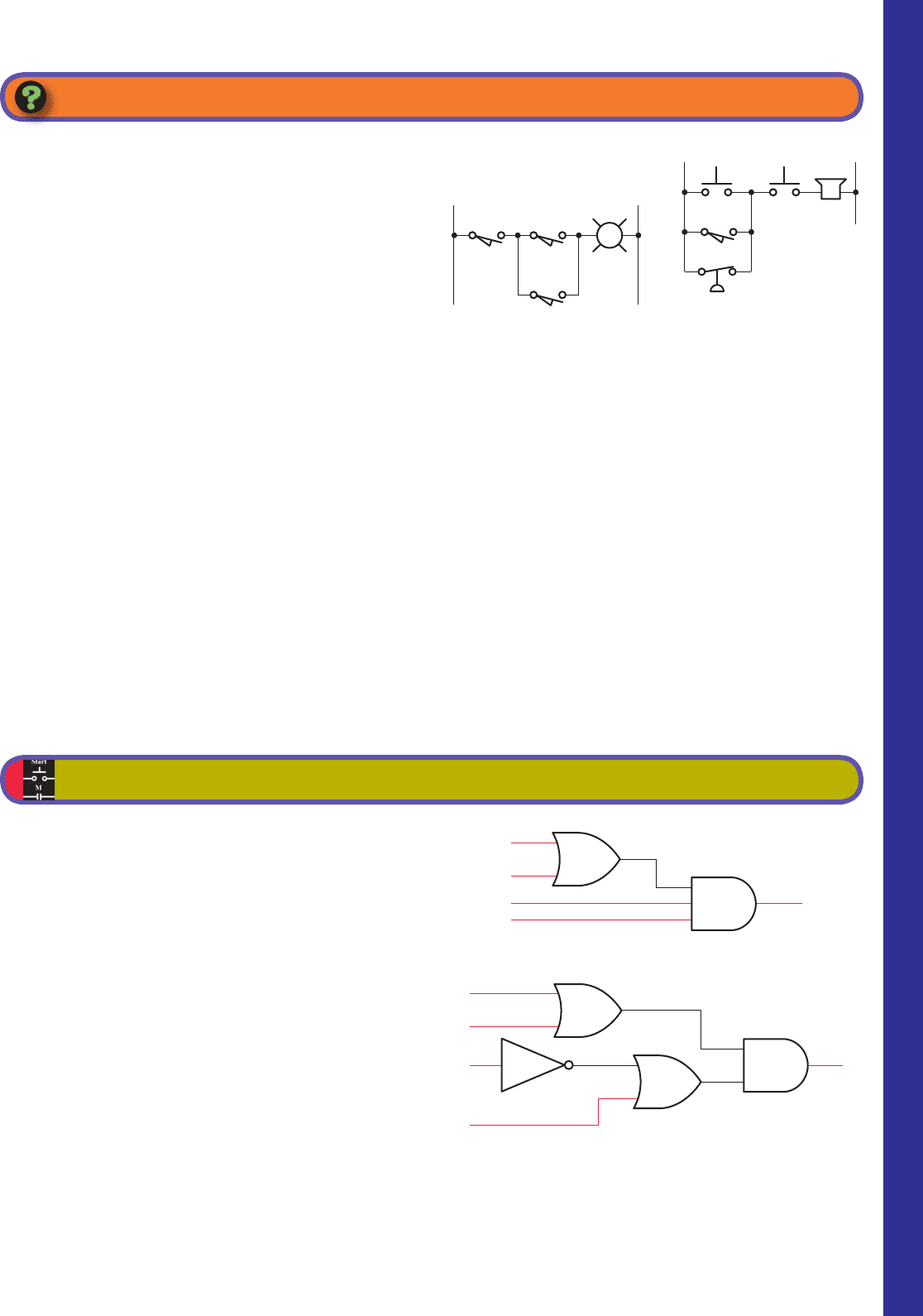
1. It is required to have a pilot light come on when all
of the following circuit requirements are met:
• All four circuit pressure switches must be
closed.
• At least two out of three circuit limit switches
must be closed.
• The reset switch must not be closed.
Using AND, OR, and NOT gates, design a logic
circuit that will solve this hypothetical problem.
2. Write the Boolean equation for each of the logic gate
circuits in Figure 4-29a–f .
3. The logic circuit of Figure 4-30 is used to acti-
vate an alarm when its output Y is logic HIGH or
1. Draw a truth table for the circuit showing the
resulting output for all 16 of the possible input
conditions.
CHAPTER 4 PROBLEMS
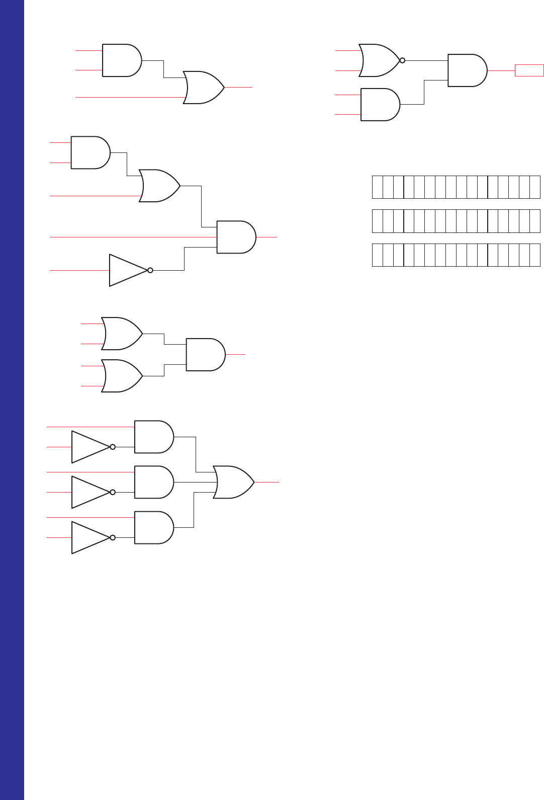
Figure 4-29 Logic gate circuits for Problem 2.
(a)
A
C
D
Y
B
(b)
A
CY
B
D
pet10882_ch04_057-070.indd 69pet10882_ch04_057-070.indd 69 7/23/10 9:12 PM7/23/10 9:12 PM
70 Chapter 4 Fundamentals of Logic
(c)
A
C
Y
B
A
C
E
(d )
B
D
Y
(e)
A
Y
B
C
D
(f )
A
C
E
Y
B
D
F
Figure 4-29 (Continued )
4. What will be the data stored in the destination ad-
dress of Figure 4-31 for each of the following logical
operations?
a. AND operation
b. OR operation
c. XOR operation
5. Write the Boolean expression and draw the gate
logic diagram and typical PLC ladder logic diagram
for a control system wherein a fan is to run only
when all of the following conditions are met:
• Input A is OFF
• Input B is ON or input C is ON, or both B and C
are ON
• Inputs D and E are both ON
• One or more of inputs F, G, or H are ON
Figure 4-30 Logic circuit for Problem 3.
Alarm
A
Y
C
D
B
Figure 4-31 Data for Problem 4.
Source A
Source B
Destination
0000
000001 1 01010
0100
00000111 0101
pet10882_ch04_057-070.indd 70pet10882_ch04_057-070.indd 70 7/23/10 9:12 PM7/23/10 9:12 PM
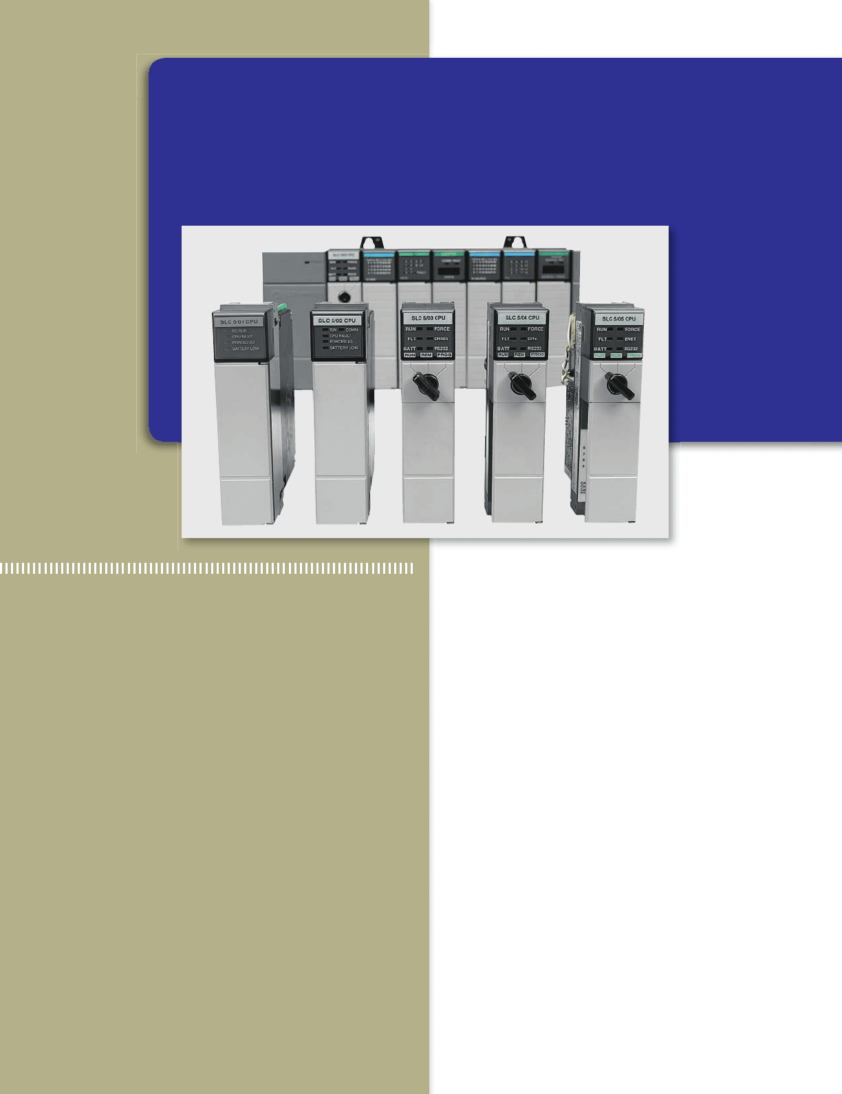
71
Each input and output PLC module terminal is
identifi ed by a unique address. In PLCs, the in-
ternal symbol for any input is a contact. Similarly,
in most cases, the internal PLC symbol for all
outputs is a coil. This chapter shows how these
contact/coil functions are used to program a
PLC for circuit operation. This chapter covers
only the basic set of instructions that perform
functions similar to relay functions. You will also
learn more about the program scan cycle and
the scan time of a PLC.
Chapter Objectives
After completing this chapter, you will be able to:
5.1 De ne and identify the functions of a PLC memory
map
5.2 Describe input and output image table
les and types
of data les
5.3 Describe the PLC program scan sequence
5.4 Understand how ladder diagram language, Boolean
language, and function chart programming language
are used to communicate information to the PLC
5.5 De
ne and identify the function of internal relay
instructions
5.6 Identify the common operating modes found in PLCs
5.7 Write and enter ladder logic programs
5
Basics of PLC Programming
Image Used with Permission of Rockwell Automation, Inc.
pet10882_ch05_071-094.indd 71pet10882_ch05_071-094.indd 71 7/23/10 9:14 PM7/23/10 9:14 PM
72 Chapter 5 Basics of PLC Programming
5.1 Processor Memory Organization
While the fundamental concepts of PLC programming are
common to all manufacturers, differences in memory or-
ganization, I/O addressing, and instruction set mean that
PLC programs are never perfectly interchangeable among
different makers. Even within the same product line of a
single manufacturer, different models may not be directly
compatible.
The memory map or structure for a PLC processor con-
sists of several areas, some of these having speci c roles.
Allen-Bradley PLCs have two different memory struc-
tures identi ed by the terms rack-based systems and tag-
based systems. The memory organization for rack-based
systems will be covered in this chapter and that for tag-
based systems in a later chapter.
Memory organization takes into account the way a
PLC divides the available memory into different sections.
The memory space can be divided into two broad catego-
ries: program les and data les. Individual sections, their
order, and the sections’ length will vary and may be xed
or variable, depending on the manufacturer and model.
Program les are the part of the processor memory
that stores the user ladder logic program. The program
accounts for most of the total memory of a given PLC
system. It contains the ladder logic that controls the ma-
chine operation. This logic consists of instructions that
are programmed in a ladder logic format. Most instruc-
tions require one word of memory.
The data les store the information needed to carry out
the user program. This includes information such as the
status of input and output devices, timer and counter val-
ues, data storage, and so on. Contents of the data table can
be divided into two categories: status data and numbers or
codes. Status is ON/OFF type of information represented
by 1s and 0s, stored in unique bit locations. Number or
code information is represented by groups of bits that are
stored in unique byte or word locations.
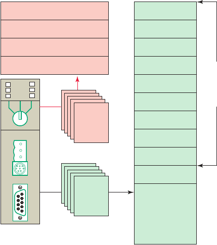
The memory organizations of the rack-based Allen-
Bradley PLC-5 and SLC 500 controllers are very similar.
Figure5-1 shows the program and data le organization
for the SLC 500 controller. The contents of each le are
as follows.
Program Files
Program
les are the areas of processor memory where
ladder logic programming is stored. They may include:
• System functions ( le 0) —This le is always
included and contains various system-related in-
formation and user-programmed information such
as processor type, I/O con guration, processor le
name, and password.
• Reserved ( le 1) —This le is reserved by the pro-
cessor and is not accessible to the user.
• Main ladder program ( le 2) —This le is always
included and contains user-programmed instructions
that de ne how the controller is to operate.
• Subroutine ladder program ( les 3–255) —These
les are user-created and are activated according to
subroutine instructions residing in the main ladder
program le.
Data Files
The data
le portion of the processor’s memory stores input
and output status, processor status, the status of various
bits, and numerical data. All this information is accessed
via the ladder logic program. These les are organized by
the type of data they contain and may include:
• Output ( le 0) —This le stores the state of the out-
put terminals for the controller.
• Input ( le 1) —This le stores the status of the
input terminals for the controller.
• Status ( le 2) —This le stores controller operation
information and is useful for troubleshooting con-
troller and program operation.
• Bit ( le 3) —This le is used for internal relay logic
storage.
• Timer ( le 4) —This le stores the timer accumu-
lated and preset values and status bits.
Figure 5-1 Program and data fi le organization for the
SLC 500 controller.
Designated
User
defined
System functions
Reserved
User program
Subroutine programs
0
1
2
3–255
0
1
2
3
4
5
6
7
8
9
Program
files
Data
files
10–255
Output image
Input image
Status
Bit
Timer
Counter
Control
Integer
Reserved
Network
Bit
Timer
Counter
Control
Integer
pet10882_ch05_071-094.indd 72pet10882_ch05_071-094.indd 72 7/23/10 9:14 PM7/23/10 9:14 PM