Petruzella F.D. Programmable Logic Controllers
Подождите немного. Документ загружается.

Developing Fundamental PLC Wiring Diagrams and Ladder Logic Programs Chapter 6 113
Status Indicating Lights —Water pump running light
(green)
- Low water level status light (red)
- High water level status light (yellow)
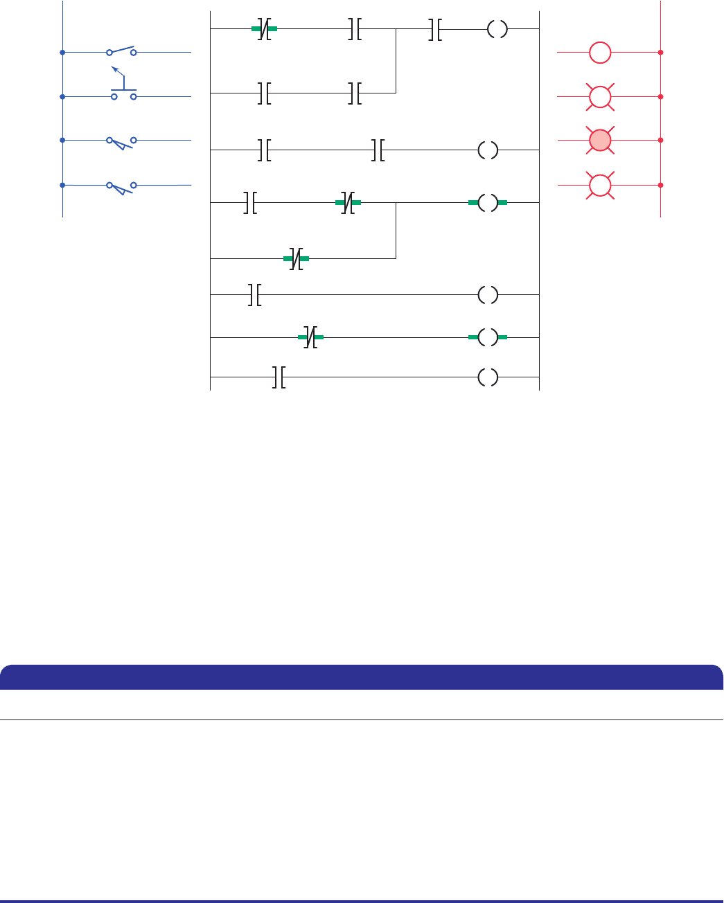
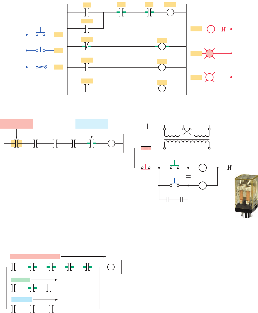
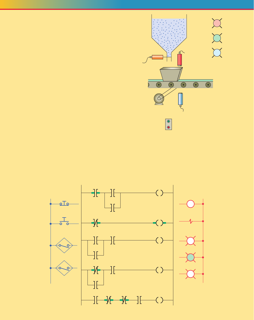
Figure 6-51 shows a program that can be used to imple-
ment control of the water level in the storage tank. The
latch and unlatch instructions form part of the program.
The operation of the program can be summarized as
follows:
• An internal storage bit is used for the latch and ad-
dress rather than an actual discrete output address.
Both have the same addresses.
• The rung 1 Examine-on instruction addressed
to the off/on switch prevents the pump motor
from starting under any condition when in the off
(open) state.
• In the MAN mode, the rung 1 Examine-on instruc-
tion addressed to the low sensor switch allows the
pump motor to operate only when the low level sen-
sor switch is closed.
• In the AUTO mode, whenever the high sensor
switch is momentarily closed the Examine-on in-
struction of rung 1 addressed to it will energize the
latch coil. The pump will begin running and con-
tinue to operate until the unlatch coil is energized by
the rung 3 Examine-off instruction addressed to the
low sensor switch.
• The pump running status light is controlled by the
rung 4 Examine-on instruction addressed to the
motor output.
• The status bit will remain set to 1 when the pushbut-
ton is released and logical continuity of the latch
rung is lost.
• When the off pushbutton (I:1/1) is momentarily ac-
tuated, the unlatch rung becomes true and the latch
status bit (O:2/5) is reset back to 0 and so the light
is switched off.
• The status bit will remain reset to 0 when the push-
button is released and logical continuity of the latch
rung is lost.
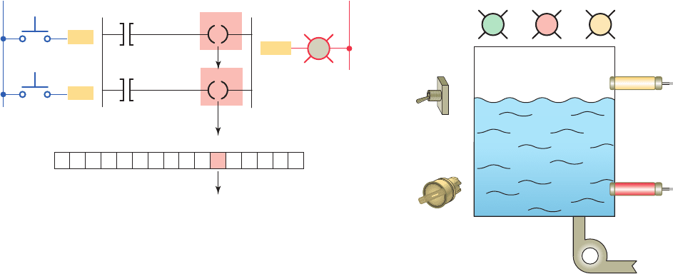
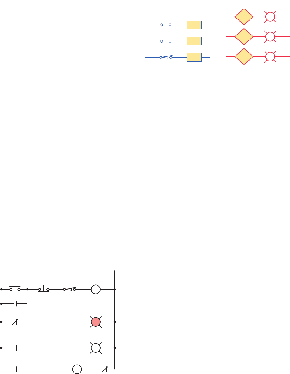
Output latch is an output instruction with a bit-level
address. When the instruction is true, it sets a bit in the
output image le. It is a retentive instruction because the
bit remains set when the latch instruction goes false. In
most applications it is used with an unlatch instruction.
The output unlatch instruction is also an output instruc-
tion with a bit-level address. When the instruction is true,
it resets a bit in the output image le. It, too, is a retentive
instruction because the bit remains reset when the instruc-
tion goes false.
The process shown in Figure 6-50 is to be used to con-
trol the level of water in a storage tank by turning a dis-
charge pump on or off. The modes of operation are to be
programmed as follows:
OFF Position —The water pump will stop if it is run-
ning and will not start if it is stopped.
Manual Mode —The pump will start if the water in
the tank is at any level except low.
Automatic Mode —If the level of water in the tank
reaches a high point, the water pump will start so that
water can be removed from the tank, thus lowering
the level.
- When the water level reaches a low point, the pump
will stop .
Figure 6-49 Output latch and output unlatch operation.
15 14 13 12 11 10 9 8 7 6 5 4 3 2 1 0
Latch
rung
I:1/0
Unlatch
rung
I:1/1
I:1/0
O:2/5
O:2/
O:2/5
O:2/5
I:1/1
ON
Inputs OutputProgram
L1 L2
OFF
PL
L
U
Status bit
Figure 6-50 Process used to control the level of water in a
storage tank.
High sensor switch
Low sensor switch
MAN/AUTO
Pump motor
ON/OFF
Pump
running
G
Low
level
R
High
level
Y
pet10882_ch06_095-124.indd 113pet10882_ch06_095-124.indd 113 7/23/10 9:22 PM7/23/10 9:22 PM
114 Chapter 6 Developing Fundamental PLC Wiring Diagrams and Ladder Logic Programs
• The low level status light is controlled by the rung
5Examine-off instruction addressed to the low
s ensor switch.
• The high level status light is controlled by the rung
6 Examine-on instruction addressed to the high
s ensor switch.
Figure 6-52 shows a typical I/O module wiring dia-
gram and addressing format for the water level control
program implemented using an Allen-Bradley modu-
lar SLC 500 controller. The chassis power supply has a
relatively small power rating and is used to supply DC
power to all devices physically mounted in the backplane
of the PLC rack. In this application a 24 VDC eld power
supply is used for the input devices and a 120 VAC eld
power supply for the output devices. This allows a low-
voltage 24-volt control signal to control 240-volt output
devices. SLC 500 controllers use a rack/slot-based ad-
dress system where the slot location of the I/O modules
in the rack establishes the PLC address. The addresses
for the eld devices of this particular application are
shown below:
L1
1
2
3
4
5
6
Input module
wiring connections
OFF ON
AutoMan
Low sensor switch
L2
High sensor switch
Man/Auto Low sensor switch
Man/Auto
Man/Auto
Latch/Unlatch
Ladder logic program
OFF/ON
Motor
Man/Auto High sensor switch
Latch coil
L
Man/Auto Low sensor switch
Unlatch coil
U
Motor
G
Low sensor switch
R
High sensor switch
Y
Motor
Output module
wiring connection
Pump running
Low level
High level
M
G
R
Y
Figure 6-51 Program used to implement control of the water level in the storage tank.
FIELD DEVICE ADDRESS Signifi es
OFF/ON Switch I:2/0 The input module in slot 2 and screw terminal 0
MAN/AUTO Switch I:2/4 The input module in slot 2 and screw terminal 4
LOW SENSOR SWITCH I:2/8 The input module in slot 2 and screw terminal 8
HIGH SENSOR SWITCH I:2/12 The input module in slot 2 and screw terminal 12
MOTOR O:3/1 The output module in slot 3 and screw terminal 1
PUMP RUNNING Light O:3/5 The output module in slot 3 and screw terminal 5
LOW LEVEL Light O:3/9 The output module in slot 3 and screw terminal 9
HIGH LEVEL Light O:3/13 The output module in slot 3 and screw terminal 13
B3:0/0 Internal retentive bit instruction that does not drive a real-word device
pet10882_ch06_095-124.indd 114pet10882_ch06_095-124.indd 114 7/23/10 9:22 PM7/23/10 9:22 PM
Developing Fundamental PLC Wiring Diagrams and Ladder Logic Programs Chapter 6 115
Ladder logic program
Low sensor switch OFF/ON
Motor
Man/Auto
Man/Auto
Man/Auto
Man/Auto
Man/Auto
Motor G
R
Y
Low sensor switch
Low sensor switch
Unlatch coil
Latch/Unlatch
High sensor switch Latch coil
I:2/4
I:2/8
I:2/4
B3:0/0
I:2/4
I:2/4 I:2/8
I:2/4
O:3/1
I:2/8
O:3/5
O:3/9
B3:0/0
I:2/12
B3:0/0
I:2/0 O:3/1
I:2/12
O:3/13
Slots
0
High sensor switch
Input module
0
1
2
3
4
5
6
7
8
9
10
11
12
13
14
15
IN 0
IN 2
IN 4
IN 6
IN 8
IN 10
IN 12
IN 14
DC
COM
IN 1
IN 3
IN 5
IN 7
IN 9
IN 11
IN 13
IN 15
DC
COM
Output module
0
1
2
3
4
5
6
7
8
9
10
11
12
13
14
15
VAC
OUT 1
OUT 3
OUT 5
OUT 7
OUT 9
OUT 11
OUT 13
OUT 15
OUT 0
OUT 2
OUT 4
OUT 6
OUT 8
OUT 10
OUT 12
OUT 14
AC
COM
24 VDC
16 point discrete
input module
240 VAC
16 point discrete
output module
24 VDC
Field device
power supply
⫹DC ⫺DC
240 VAC
M
Field device
power supply
L2 L1
Power
supply
123456
OFF ON
Man
Motor
Pump running
Low level
High level
Auto
Low sensor
switch
High sensor
switch
R
G
Y
L
U
Figure 6-52 Water level control program implemented using an Allen-Bradley modular SLC 500 controller.
pet10882_ch06_095-124.indd 115pet10882_ch06_095-124.indd 115 7/23/10 9:22 PM7/23/10 9:22 PM
116 Chapter 6 Developing Fundamental PLC Wiring Diagrams and Ladder Logic Programs
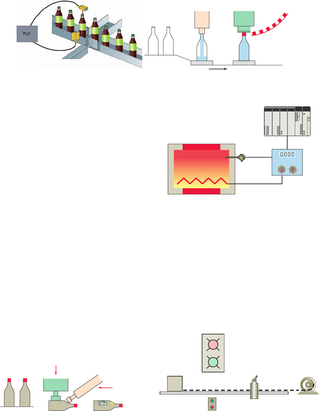
Automatic control involves maintaining a desired set
point at an output. One example is maintaining a certain
set-point temperature in a furnace as illustrated in Fig-
ure6-55 . If there is deviation from that set point, an error
is determined by comparing the output against the set point
and using this error to make a correction. This requires
feedback from the output to the control for the input.
The converting of a simple sequential process can be
examined with reference to the process ow diagram illus-
trated in Figure 6-56 . The sequential task is as follows:
1. Start button is pressed.
2. Table motor is started.
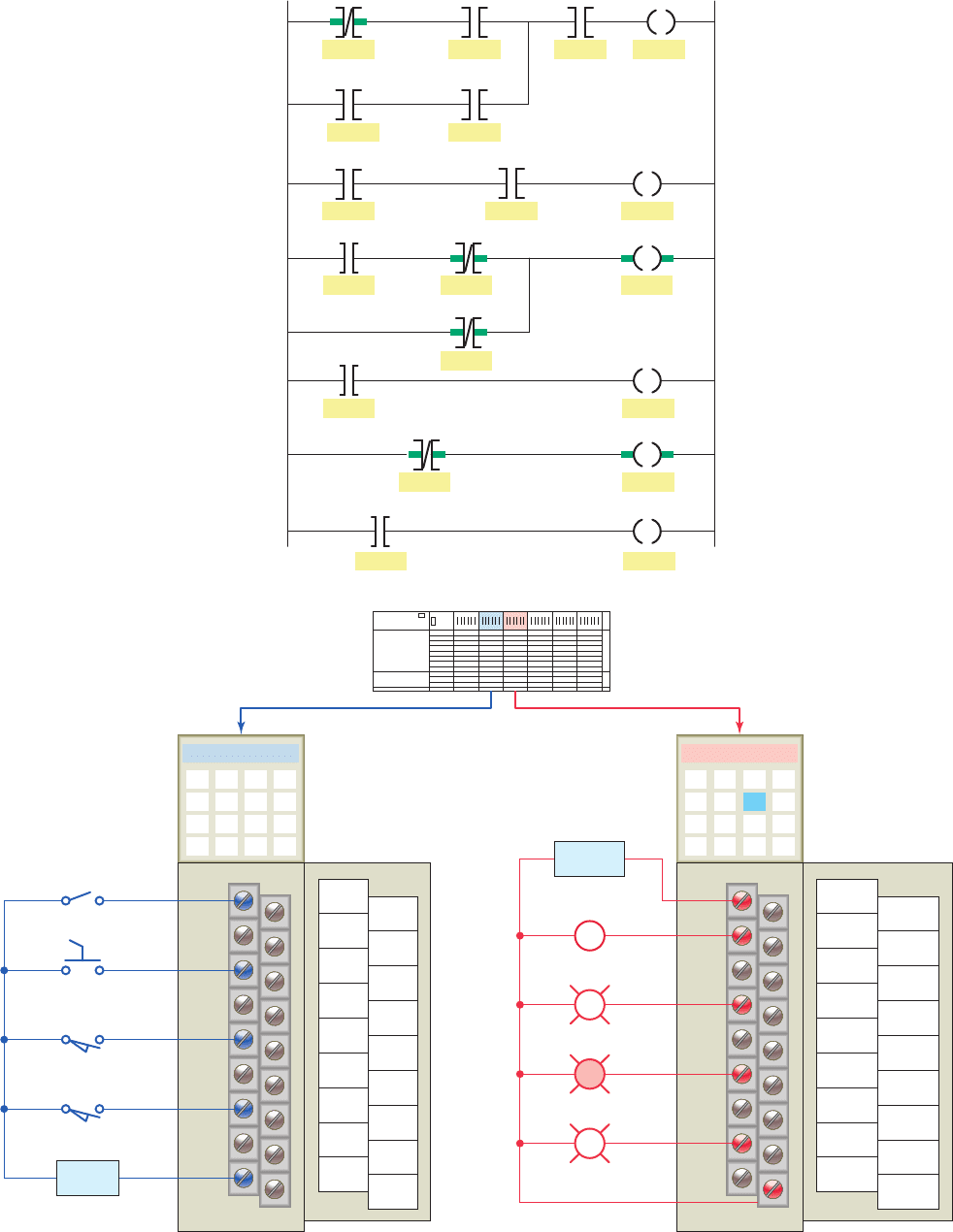
Figure 6-53 Sequential control process.
Source: Photo courtesy Omron Industrial Automation, www.ia.omron.com.
1 - Filling operation 2 - Capping operation
Figure 6-54 Combination control process.
Label solenoid 1
Label
solenoid 2
6.10 Converting Relay Schematics
into PLC Ladder Programs
The best approach to developing a PLC program from a
relay schematic is to understand rst the operation of each
relay ladder rung. As each relay ladder rung is understood,
an equivalent PLC rung can be generated. This process
will require access to the relay schematic, documentation
of the various input and output devices used, and possibly
a process ow diagram of the operation.
Most control processes require the completion of several
operations to produce the required output. Manufacturing,
machining, assembling, packaging, nishing, or transport-
ing of products requires the precise coordination of tasks.
A sequential control process is required for processes
that demand that certain operations be performed in a spe-
ci c order. Figure 6-53 illustrates part of a bottle lling
process. In the lling and capping operations, the tasks
are (1) ll bottle and (2) press on cap. These tasks must
be performed in the proper order. Obviously we could not
ll the bottle after the cap is pressed on. This process,
therefore, requires sequential control.
Combination controls require that certain operations
be performed without regard to the order in which they
are performed. Figure 6-54 illustrates another part of the
same bottle lling process. Here, the tasks are (1) place
label 1 on bottle and (2) place label 2 on bottle. The order
in which the tasks are performed does not really matter.
In fact, however, many industrial processes that are not in-
herently sequential in nature are performed in a sequential
manner for the most ef cient order of operations.
Figure 6-55 Automatic control process.
PLC
Furnace
Feedback
Controller
Figure 6-56 Sequential process fl ow diagram.
Package
Limit
switch
Motor
Pilot lights
Stop
Start
R
G
pet10882_ch06_095-124.indd 116pet10882_ch06_095-124.indd 116 7/23/10 9:22 PM7/23/10 9:22 PM
Developing Fundamental PLC Wiring Diagrams and Ladder Logic Programs Chapter 6 117
Figure 6-58 shows an I/O connection diagram for a
programmed version of the sequential process. Each input
and output device is represented by its symbol and asso-
ciated address. These addresses will indicate what PLC
input is connected to what input device and what PLC
output will drive what output device. The address code, of
course, will depend on the PLC model used. This example
uses SLC 500 addressing for the process. Note that the
electromagnetic control relay CR is not needed because
its function is replaced by an internal PLC control relay.
The hardwired relay schematic for the sequential pro-
cess can be converted to the PLC ladder logic program
shown in Figure 6-59 . In converting the process to a pro-
gram the operation of each rung must be understood. The
pushbuttons PB1, PB2 as well as limit switch LS are all
programmed using the examine-closed (–] [–) instruction
to produce the desired logic control. Also, internal relay
B3:1/0 is used to replace control relay CR. To obtain the
desired control logic, all internal relay contacts are pro-
grammed using the PLC contact instruction that matches
the coil de-energized state. The internal relay imple-
mented in software requires one coil address the contacts
of which can be examined for an ON or OFF condition as
many times as you like.
There is more than one method to correctly design the
ladder logic program for a given control process. In some
cases one arrangement may be more ef cient in terms of
the amount of memory used and the time required to scan
the program. Figure 6-60 illustrates an example of an ar-
rangement of series instructions of a rung programmed
for optimum scan time. The series instructions are pro-
grammed from the most likely to be false (far left) to
the least likely to be false (far right). Once the processor
sees a false input instruction in series, the processor stops
checking the rung at the false condition and sets the out-
put false.
Figure 6-61 illustrates an example of an arrangement
of parallel instructions of a rung programmed for opti-
mum scan time. The parallel path that is most often true is
3. Package moves to the position of the limit switch
and automatically stops.
Other auxiliary features include:
• A stop button that will stop the table, for any reason,
before the package reaches the limit switch position
• A red pilot light to indicate the table is stopped
• A green pilot light to indicate the table is running
A relay schematic for the sequential process is shown
in Figure 6-57 . The operation of this hardwired circuit can
be summarized as follows:
• Start button is actuated; CR is energized if stop but-
ton and limit switch are not actuated.
• Contact CR-1 closes, sealing in CR when the start
button is released.
• Contact CR-2 opens, switching the red pilot light
from on to off.
• Contact CR-3 closes, switching the green pilot light
from off to on.
• Contact CR-4 closes to energize the motor starter
coil, starting the motor and moving the package to-
ward the limit switch.
• Limit switch is actuated, de-energizing relay
coilCR.
• Contact CR-1 opens, opening the seal-in circuit.
• Contact CR-2 closes, switching the red pilot light
from off to on.
• Contact CR-3 opens, switching the green pilot light
from on to off.
• Contact CR-4 opens, de-energizing the motor starter
coil to stop the motor and end the sequence.
Figure 6-57 Relay schematic for the sequential process.
PB1
Start
L1 L2
PB2
Stop
LS
Limit
switch
Control
relay
CR-2
CR-3
CR-4
CR-1
OL
PL1
Stop
PL2
Run
Motor
starter coil
R
G
CR
M
O:4/2
OutputsInputs
LS - Limit switch
L2L1
L2
L1
PB1 - Start
Motor starter
coil
O:4/1
PL1 - Stop
I:3/0
I:3/2
I:3/1
PB1 - Stop
R
M
O:4/3
PL2 - Run
G
Figure 6-58 I/O connection diagram.
pet10882_ch06_095-124.indd 117pet10882_ch06_095-124.indd 117 7/23/10 9:22 PM7/23/10 9:22 PM
118 Chapter 6 Developing Fundamental PLC Wiring Diagrams and Ladder Logic Programs
placed on the top of the rung. The processor will not look
at the others unless the top path is false.
Figure 6-62 shows a hardwired jog control circuit that
incorporates a jog control relay. The operation of the cir-
cuit can be summarized as follows:
• Pressing the start pushbutton completes a circuit for
the CR coil, closing the CR1 and CR2 contacts.
• The CR1 contact completes the circuit for the M
coil, starting the motor.
• The M maintaining contact closes; this maintains
the circuit for the M coil.
• Pressing the jog button energizes the M coil only,
starting the motor. Both CR contacts remain open,
and the CR coil is de-energized. The M coil will
not remain energized when the jog push button is
released.
Figure 6-63 shows a PLC program equivalent of the
hardwired relay jog circuit. Note that the function of the
control relay is now accomplished using an internal PLC
instruction (B3:1/0).
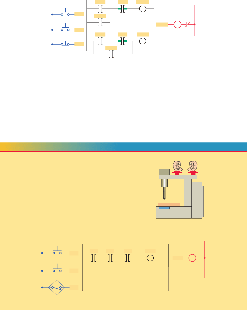
Figure 6-59 Sequential process PLC ladder logic program.
L1
Input module
wiring connections
PB1
PB2
L2
LS
I:3/2
I:3/1
I:3/0
I:3/0
B3:1/0
B3:1/0
B3:1/0
B3:1/0
I:3/1
Ladder logic program
I:3/2 B3:1/0
PB1 PB2 LS
Internal
relay
O:4/2
PL1
O:4/3
PL2
O:4/1
M
O:4/1
O:4/2
Output module
wiring connection
PL1
O:4/3
PL2
OL
R
M
G
Instruction most
likely to be FALSE
Instruction least
likely to be FALSE
Figure 6-60 Series instructions programmed for optimum
scan time.
Path most likely to be TRUE
Less likely
Least likely
Figure 6-61 Parallel instructions programmed for
optimum scan time.
OL
Control relay
AB
H1 H3
H2 H4
X1 X2
120 V
Start
Jog
CR2
CR1
M
Stop
CR
M
Figure 6-62 Jog circuit with control relay.
Source: Photo courtesy IDEC Corporation, www.IDEC.com/usa, RR Relay.
pet10882_ch06_095-124.indd 118pet10882_ch06_095-124.indd 118 7/23/10 9:22 PM7/23/10 9:22 PM
Developing Fundamental PLC Wiring Diagrams and Ladder Logic Programs Chapter 6 119
I:3/0
B3:1/0
I:3/1 B3:1/0
I:3/2
B3:1/0
I:3/1 O:2/2
O:2/2
Ladder logic program
Start
L1 L2
Inputs Output
Stop
Internal
relay
Jog
Jog
Stop M
I:3/2
Start
Stop
I:3/0
I:3/1
M
OL
Figure 6-63 PLC program equivalent of the hardwired relay jog circuit.
6.11 Writing a Ladder Logic Program
Directly from a Narrative Description
In most cases, it is possible to prepare a ladder logic program
directly from the narrative description of a control process.
Some of the steps in planning a program are as follows:
• D e ne the process to be controlled.
• Draw a sketch of the process, including all sensors
and manual controls needed to carry out the control
sequence.
• List the sequence of operational steps in as much
detail as possible.
• Write the ladder logic program to be used as a basis
for the PLC program.
• Consider different scenarios where the process se-
quence may go astray and make adjustments as needed.
• Consider the safety of operating personnel and
make adjustments as needed.
The following are examples of ladder logic programs
derived from narrative descriptions of control processes.
Figure 6-64 shows the sketch of a drilling process that
requires the drill press to turn on only if there is a part
present and the operator has one hand on each of the
start switches. This precaution will ensure that the opera-
tor’s hands are not in the way of the drill.
The sequence of operation requires that switches 1
and 2 and the part sensor all be activated to make the
drill motor operate. Figure 6-65 shows the ladder logic
program required for the process implemented using an
SLC 500 controller.
EXAMPLE 6-1
L1
Inputs
Ι:3/5
Sensor
Ι:3/6
Ι:3/4
Ladder logic program
Motor
contactor
PB1 PB1
Sensor
Motor
contactor
PB1
PB2
Ι:3/4 Ι:3/5 Ι:3/6
O:4/0
O:4/0
L2
Output
M
Figure 6-65 Drilling process PLC program.
PB1
Drill
motor
Switches
PB2
Part sensor
Figure 6-64 Sketch of the drilling process.
pet10882_ch06_095-124.indd 119pet10882_ch06_095-124.indd 119 7/23/10 9:22 PM7/23/10 9:22 PM
120 Chapter 6 Developing Fundamental PLC Wiring Diagrams and Ladder Logic Programs
A motorized overhead garage door is to be operated au-
tomatically to preset open and closed positions. The fi eld
devices include one of each of the following:
• Reversing motor contactor for the up and down
directions.
• Normally closed down limit switch to sense when the
door is fully closed.
• Normally closed up limit switch to sense when the
door is fully opened.
• Normally open door up button for the up direction.
• Normally open door down button for the down
direction.
• Normally closed door stop button for stopping the
door.
• Red door ajar light to signal when the door is partially
open.
• Green door open light to signal when the door is fully
open.
• Yellow door closed light to signal when the door is fully
closed.
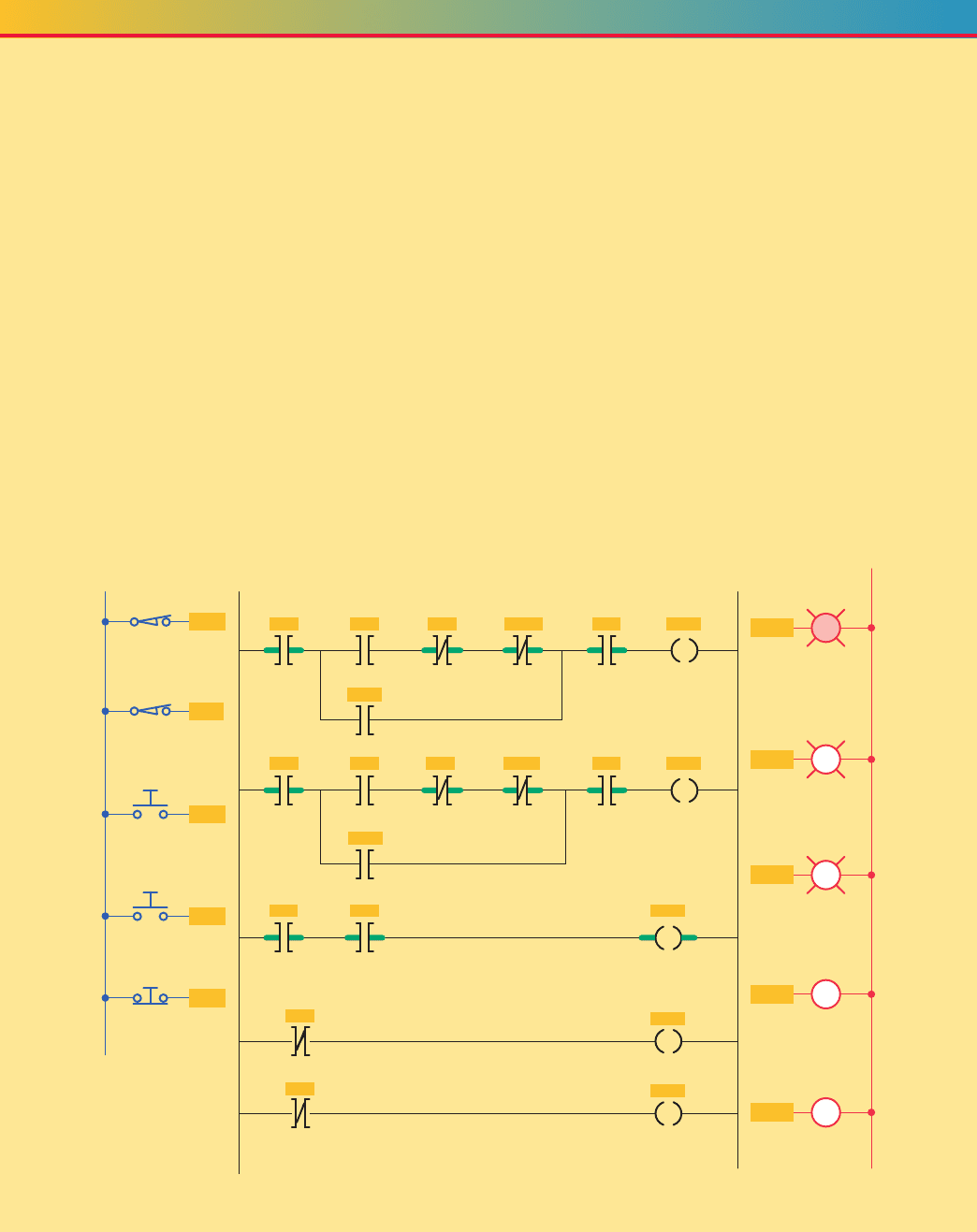
The sequence of operation requires that:
• When the up button is pushed, the up motor contac-
tor energizes and the door travels upward until the up
limit switch is actuated.
• When the down button is pushed, the down motor
contactor energizes and the door travels down until
the down limit switch is actuated.
• When the stop button is pushed, the motor stops.
The motor must be stopped before it can change
direction.
Figure 6-66 shows the ladder logic program required for
the operation implemented using an SLC 500 controller.
EXAMPLE 6-2
Figure 6-66 Motorized overhead garage door PLC program.
L1
Input devices
(shown in unactuated
condition)
Output devices
Up limit
L2
Door up
Ι:3/0
Ι:3/7
Program
O:4/3
O:4/0
Door ajar
Door down
Stop door
Ι:3/4 Ι:3/5
Down limit
Ι:3/1
Ι:3/4
Ι:3/5
Ι:3/7
O:4/4 Ι:3/0
Stop Motor upUp
Ι:3/0 O:4/0Ι:3/1
Up limit Door ajarDown limit
Ι:3/0
O:4/1
Up limit
Door open
O:4/3
Motor up
Down
Down
Intrlock Up limit
O:4/4
Ι:3/1
O:4/2
Down limit
Door closed
Motor down
O:4/4
Motor down
Ι:3/7 Ι:3/5 Ι:3/4 O:4/3 Ι:3/1
Stop Down Up
Up
intrlock Down limit
O:4/1
Door open
O:4/2
Door
closed
O:4/3
Motor
contactor
O:4/4
Motor
contactor
R
G
Y
UP
DN
pet10882_ch06_095-124.indd 120pet10882_ch06_095-124.indd 120 7/23/10 9:22 PM7/23/10 9:22 PM
Developing Fundamental PLC Wiring Diagrams and Ladder Logic Programs Chapter 6 121
Figure 6-67 shows the sketch of a continuous fi lling opera-
tion. This process requires that boxes moving on a con-
veyor be automatically positioned and fi lled.
The sequence of operation for the continuous fi lling op-
eration is as follows:
• Start the conveyor when the start button is momen-
tarily pressed.
• Stop the conveyor when the stop button is momen-
tarily pressed.
• Energize the run status light when the process is
operating.
• Energize the standby status light when the process is
stopped.
• Stop the conveyor when the right edge of the box is
fi rst sensed by the photosensor.
• With the box in position and the conveyor stopped,
open the solenoid valve and allow the box to fi ll. Filling
should stop when the level sensor goes true.
• Energize the full light when the box is full. The full light
should remain energized until the box is moved clear
of the photosensor.
Figure 6-68 shows the ladder logic program required for
the operation.
EXAMPLE 6-3
Figure 6-67 Sketch of the continuous fi lling operation.
Run
Standby
PL
PL
Full
Level
switch
Photo
switch
Motor
Start
Solenoid
Hopper
Stop
PL
L1
Stop
Start
Photo
L2
Level
Stop Start
Run
Ladder logic program
Run
Run
Standby
OutputsInputs
Motor
Solenoid
Run
Standby
Full
Level Photo
Full
Full
Photo Run
Level Photo
Motor
Run
Solenoid
Full
Full
Figure 6-68 Continuous fi lling operation PLC program.
pet10882_ch06_095-124.indd 121pet10882_ch06_095-124.indd 121 7/27/10 10:13 PM7/27/10 10:13 PM

122 Chapter 6 Developing Fundamental PLC Wiring Diagrams and Ladder Logic Programs
1. Explain the basic operating principle of an electro-
magnetic control relay.
2. What is the operating difference between a nor-
mally open and a normally closed relay contact?
3. In what ways are control relay coils and contacts
rated?
4. How do contactors differ from relays?
5. What is the main difference between a contactor
and a magnetic motor starter?
6. a. Draw the schematic for an across-the-line AC
magnetic motor starter.
b. With reference to this schematic, explain the
function of each of the following parts:
i. Main contact M
ii. Control contact M
iii. Starter coil M
iv. OL relay coils
v. OL relay contact
7. The current requirement for the control circuit of a
magnetic starter is normally much smaller than that
required by the power circuit. Why?
8. Compare the method of operation of each of the
following types of switches:
a. Manually operated switch
b. Mechanically operated switch
c. Proximity switch
9. What do the abbreviations NO and NC represent
when used to describe switch contacts?
10. Draw the electrical symbol used to represent each
of the following switches:
a. NO pushbutton switch
b. NC pushbutton switch
c. Break-make pushbutton switch
d. Three-position selector switch
e. NO limit switch
f. NC temperature switch
g. NO pressure switch
h. NC level switch
i. NO proximity switch
11. Outline the method used to actuate inductive and
capacitive proximity sensors.
12. How are reed switch sensors actuated?
13. Compare the operation of a photovoltaic solar cell
with that of a photoconductive cell.
14. What are the two basic components of a photoelec-
tric sensor?
15. Compare the operation of the re ective-type and
through-beam photoelectric sensors.
16. Give an explanation of how a scanner and a de-
coder act in conjunction with each other to read a
bar code.
17. How does an ultrasonic sensor operate?
18. Explain the principle of operation of a strain gauge.
19. Explain the principle of operation of a thermocouple.
20. What is the most common approach taken with re-
gard to the measurement of uid ow?
21. Explain how a tachometer is used to measure rota-
tional speed.
22.
How does an optical encoder work?
23. Draw an electrical symbol used to represent each of
the following PLC output control devices:
a. Pilot light
b. Relay
c. Motor starter coil
d. OL relay contact
e. Alarm
f. Heater
g. Solenoid
h. Solenoid valve
i. Motor
j. Horn
24. Explain the function of each of the following
actuators:
a. Solenoid
b. Solenoid valve
c. Stepper motor
25. Compare the operation of open-loop and closed-
loop control.
26. What is a seal-in circuit?
27. In what is the construction and operation of an
electromechanical latching relay different from a
standard relay?
28. Give a short description of each of the following
control processes:
a. Sequential
b. Combination
c. Automatic
CHAPTER 6 REVIEW QUESTIONS
pet10882_ch06_095-124.indd 122pet10882_ch06_095-124.indd 122 7/23/10 9:22 PM7/23/10 9:22 PM